

MII 53225 Datasheet
53225
SOLID-STATE POWER CONTROLLER (SSPC)
Mii
HYBRID MICROELECTRONICS
PRODUCTS DIVISION
Features:
2
t output trip
• I
• Output trip status
• 1000 VRMS Isolation
• Power FET Output
Low On-state Resistance
• Full Military compliance
• Low control power consumption (3 mA @ 5 V
typical)
• 125ºC screening available
DESCRIPTION
The 53225 is a military SPST solid-state relay. This light-weight device is mechanically resistant and electrically immune
to contact-related problems inherent in mechanical relays.
2
An I
t current let-through curve assures power supply, relay, and load protection from thermal stress yet provides large
momentary currents to charge capacitive loads or start inductive loads. Any current versus time above the I
initiates a trip condition and a status output is generated.
Effective isolation of 1000 VRMS is provided from all inputs, case and outputs through magnetic coupling. Magnetic
coupling contributes to very low control power, repeatable turn-on/turn-off times, and no output stage currents to provide
status signals.
Applications:
• Logic controlled circuit breakers
• Dynamic load switching
• Power distribution switch
• Supply source switching
2
t curve
Micropac Industries cannot assume any responsibility for any circuits shown or represent that they are free from patent infringement.
Micropac reserves the right to make changes at any time in order to improve design and to supply the best product possible.
MICROPAC INDUSTRIES, INC. HYBRID MICROELECTRONICS PRODUCTS DIVISION • 905 E. Walnut St., Garland, TX 75040 • (972) 272-3571 • Fax (972) 494-2281
www.micropac.com E-MAIL: hybridsales@micropac.com
12/10/01
1
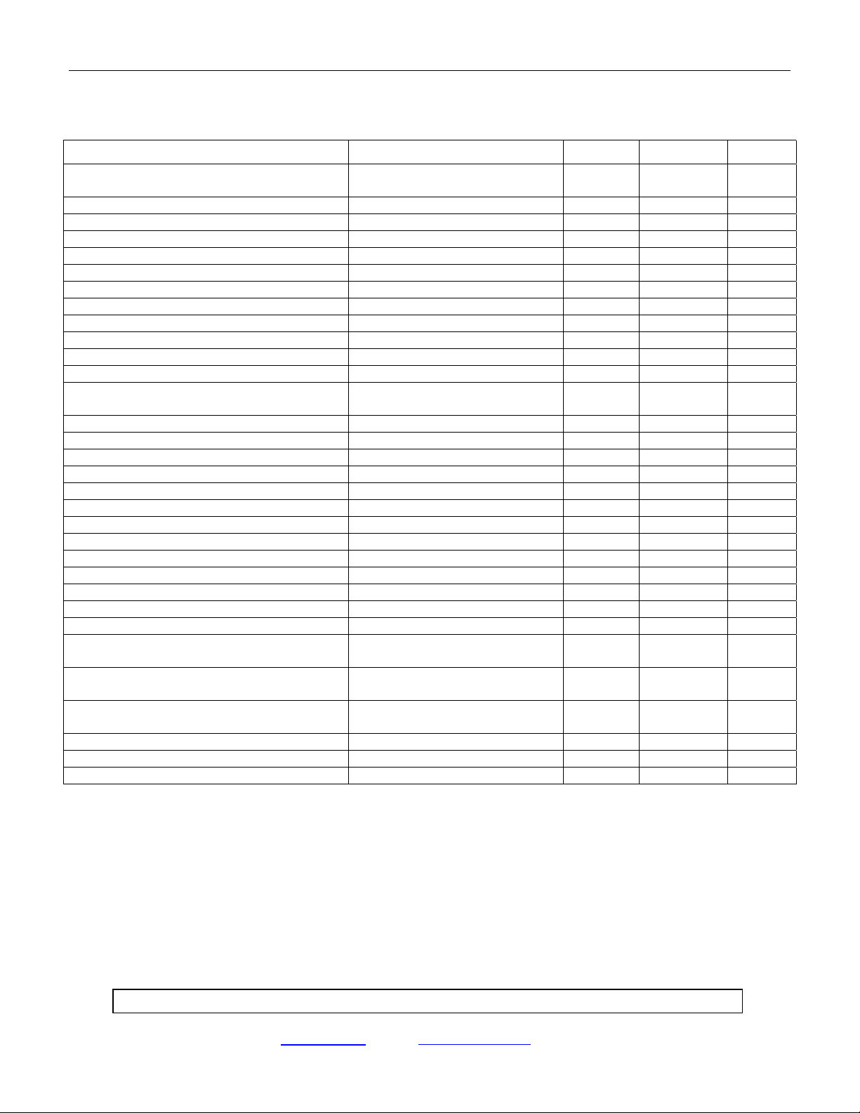
53225 SOLID-STATE POWER CONTROLLER (SSPC)
ELECTRICAL CHARACTERISTICS
(-55°C ≤ TA ≤ 85°C, V
= 5 V, V
BIAS
+ = 28 V, I
OUT
= 1.5 A unless otherwise noted)
OUT
CHARACTERISTIC CONDITION MIN MAX UNITS
2 Terminal Configuration (see Fig. 2)
5MADC
Input Current
Turn off voltage (VIN)1.5VDC
Turn on voltage (VIN)3.8VDC
Bias supply voltage range 4 6 VDC
3 Terminal Configuration (see Fig. 1)
Control input Current V
= 5 VDC 250 µADC
CONT
Control voltage range 0 6 VDC
Bias supply voltage range 0.5 6 VDC
Bias supply current 5mADC
Turn off voltage (V
CONTROL
Turn on voltage (V
Noise Margin V
Continuous off leakage current
(not tripped)
)3.9VDC
CONTROL
)0.3VDC
– V
V
V
OFF
OUT+
OUT-
ON
= 60 VDC
= Ground 150 µADC
0.5 VDC
Output on voltage drop IL = 1.5 A 0.45 VDC
Continuous operating load voltage 60 VDC
Transient blocking voltage @ 1.0 mA 80 VDC
On resistance RDS
(ON)
I
= 100 mADC 0.30 OHMS
LOAD
Turn on time 3.0 MS
Turn off time 1.0 MS
Operating frequency 20 HZ
DV/DT 100 V/µM
Electrical system spike ±600 Peak
Output Capacitance 25 VDC, 100 kHz 1000 PF
Input to output capacitance 15 PF
Dielectric strength @ 1.0 mA maximum leakage 1000 VAC
Insulation resistance @ 500 VDC, TA – 25°C 10
Surge Current
(see Fig. 4)
Guaranteed no trip
@ 10 A surge
Trip Reset Time Remove short / overload
3
OHMS
70 Typ. MS
50 Ms
& Cycle input
Status Output Specification
5.0 32 VDC
Status Supply Voltage (open Collector)
Status off leakage current VS = 15 VDC 4 µADC
Status on voltage I
High-To-Low Transition Time I
= 5 MA 0.4 VDC
STATUS
= 5 MA 1.0 MS
STATUS
Notes:
1. Input transition should be ≤ MSEC duration and input drive should be “bounceless contact” type.
Micropac Industries cannot assume any responsibility for any circuits shown or represent that they are free from patent infringement.
Micropac reserves the right to make changes at any time in order to improve design and to supply the best product possible.
MICROPAC INDUSTRIES, INC. HYBRID MICROELECTRONICS PRODUCTS DIVISION • 905 E. Walnut St., Garland, TX 75040 • (972) 272-3571 • Fax (972) 494-2281
www.micropac.com E-MAIL: hybridsales@micropac.com
12/10/01
2
 Loading...