

MII 53217 Datasheet
53217
SPST SOLID-STATE POWER CONTROLLERS
Features:
• Short circuit protection with status output
• SPST, normally open
• Up to 1000 V RMS isolation
• Output current up to 3 Amps DC
• Power FET output
Applications:
• Ideal for 270V bus applications
• Aircraft Power Distribution
• Military/High Reliability Systems
• Satellite/Space Systems
MICROCIRCUITS PRODUCTS
• Low on-state resistance
• Full military temperature operation:
-55ºC to +125ºC
• Military environmental screening available
DESCRIPTION
The 53217 is a military SPST high power, solid-state relay. It is a light-weight device resistant to damage from shock and
vibration, and immune to contact-related problems (contamination, arcing) associated with mechanical equivalents.
Transformer coupling between the input and output stages provides effective isolation up to 1000 V RMS. The Power FET
output eliminates bipolar offset and minimizes output voltage drop.
The control input may be driven by either CMOS or TTL logic, and the bias supply will accommodate 3.8 through 32 VDC.
(See figures 1 & 2)
Integral short-circuit protection with status output is provided. These units sense excessive current flow while under load or
while switching, and respond by opening the output. An open-collector status output is available to indicate that the short
circuit protection has been activated. The output will remain blocked indefinitely until the short is removed and the unit reset.
This feature prevents damage to the controller and also averts further system failures that may be caused by the short circuit.
Status line output remains on until the relay is turned off for resetting. Resetting the unit can be accomplished by recycling
the input control.
This device is available in a variety of quality levels from COTS to class K including any custom screening requirements.
The basic data sheet part is environmentally screened to H level in accordance with Table C-IX of MIL-PRF-38534, which
includes no element evaluation or QCI.
ABSOLUTE MAXIMUM RATINGS
Isolation voltage1.......................................................................................................................................................1000 V RMS
Continuous operating output voltage
Load Current
Bias supply voltage, V
2
: 53217 ...........................................................................................................................................................3.0 A
....................................................................................................................................... 3.8 to 32 VDC
DD
3
: 53217................................................................................................................400 VDC
Operating temperature ............................................................................................................................ -55ºC to +125ºC Case
Storage temperature ..........................................................................................................................................-55ºC to +125ºC
Notes:
1
60 Hz sine wave
2
At TC = 125ºC max
3
Reversing polarity on the output may cause permanent damage
4
Devices will not tolerate “short while on” at load voltages exceeding 28 VDC
Micropac Industries cannot assume any responsibility for any circuits shown or represent that they are free from patent infringement.
Micropac reserves the right to make changes at any time in order to improve design and to supply the best product possible.
MICROPAC INDUSTRIES, INC. MICROCIRCUITS PRODUCTS DIVISION • 905 E. Walnut St., Garland, TX 75040 • (972) 272-3571 • Fax (972) 494-2281
www.micropac.com
E-MAIL: hybridsales@micropac.com 8/12/02
Mii
DIVISION
Pg. 1 of 6
53217
SPST SOLID-STATE POWER CONTROLLERS
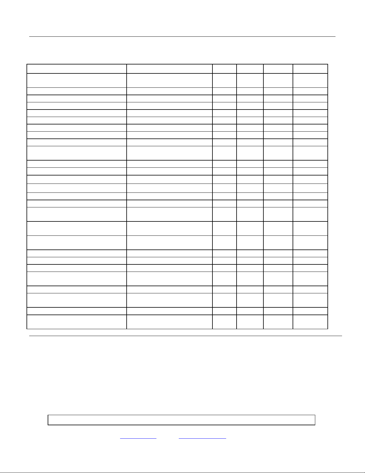
ELECTRICAL CHARACTERISTICS
TA = +25° C
PARAMETER TEST CONDITIONS MIN TYP MAX UNITS
Input characteristics
CMOS configurations (Figure 1)
Bias supply range, VDD 3.8 32 VDC
Bias current 3 5 mA
Input current 5 VDC Input 250
Control voltage range 3.8 18 VDC
Turn-off voltage 2.8 VDC
Turn-on voltage 0.5 VDC
Total Hysteresis 1.8 VDC
Dielectric strength 60 Hz 1000 V RMS
Input characteristics
TTL configuration (Figure 2)
Input current 3 5 mA
Control voltage range 3.8 32 VDC
Turn-off voltage Note 5 1.5 VDC
Turn-on voltage Note 5 3.8 VDC
Status on voltage On at 5 mA SINKING CURRENT 0.4 Volts
Status off leakage Off at 20 V 20
Output characteristics
Output current::
Continuous blocking voltage
On-state resistance, Rds
Turn-on time @ 25ºC case 0.4 0.8 ms
Turn-off time @ 25ºC case 0.5 2.0 ms
Off-state leakage At Maximum Blocking Voltage 40 100
Output Capacitance
Short-circuit current 25ºC 6 A
Short-circuit peak Shorted while on at 25ºC
Junction temperature 150 ºC
Thermal resistance,
θ
JA
θ
JC
At TC = 125ºC case temperature
25ºC Case 0.50 Ohms
µ
A
µ
A
400 VDC
700 pF
See Figure 3
30
3.0
100 A
5
A
µ
A
ºC/W
ºC/W
APPLICATION NOTES:
1. Maximum input switching frequency not to exceed 20 Hz under normal conditions, or 1 Hz if output is shorted.
2. Input transitions should be <1 ms and duration and input source should be “bounceless contact” type.
3. Inductive loads must be diode suppressed.
4. Peak current that may flow when output is shorted.
5. Devices will not tolerate “short while on” at load voltages exceeding 28 VDC.
Micropac Industries cannot assume any responsibility for any circuits shown or represent that they are free from patent infringement.
Micropac reserves the right to make changes at any time in order to improve design and to supply the best product possible.
MICROPAC INDUSTRIES, INC. MICROCIRCUITS PRODUCTS DIVISION • 905 E. Walnut St., Garland, TX 75040 • (972) 272-3571 • Fax (972) 494-2281
www.micropac.com
E-MAIL: hybridsales@micropac.com 8/12/02
Pg. 2 of 6
 Loading...