

miGuard AWI Installation & Operating Instructions Manual
MGAW1_V1.0_1545
Disposal and Recycling
Disposal of this product is covered by the Waste Electrical or Electronic Equipment (WEEE)
Directive. It should not be disposed of with other household or commercial waste.
At the end of its useful life the packaging and product should be disposed of via a suitable
recycling centre. Please contact your local authority or the retailer from where the product
was purchased for information on available facilities.
Response Electronics Limited
Roman House, Lysons Avenue, Ash Vale, Surrey, GU12 5QF
email: info@responseelectronics.com
www.responseelectronics.com
@ResponseLTD
Remote Monitoring WiFi
Communicating Wireless Alarm System
Installation & Operating
Instructions
AW1
0345 257 1000
miGuard Customer Helpline
lines open 0900 to 1700 Monday to Friday

Foreword
Dear Customer,
Congratulations on your purchase of the miGuard AW1 Alarm System. Before you
commence installation we recommend that you unpack the product, familiarise
yourself with the component parts, and carefully read through this instruction
guide.
There are some parts of the installation that must be completed in the order shown
to ensure successful installation.
Disclaimer
All statements, technical information and recommendations in this manual
are believed to be reliable, but the accuracy and completeness thereof are not
guaranteed or warranted.
The specications and information regarding the products as shown in this
document are subject to change without notice.
The reproduction, language translation modication, storage in a retrieval system
or retransmission, in any form or by any means, electronic, mechanical or otherwise,
is strictly prohibited without prior written permission.
In no event are we liable for any indirect, special, incidental, or consequential
damages, including, without limitation, lost prots or loss or damage to data arising
out of the use or inability to use this document.
Contents
Packing List ..........................................................................................................................................1
Control Panel .................................................................................................................................. 2~3
Remote Control ...................................................................................................................................4
Door/Window Sensor ........................................................................................................................5
Pet Friendly PIR Motion Sensor ....................................................................................................6-7
Pairing New Accessories to the Control Panel .............................................................................7
WiFi Setup .........................................................................................................................................8-9
App Control and Settings .........................................................................................................10-12
Notications ....................................................................................................................................... 13
Installation .................................................................................................................................... 14-17
Replacing Accessory Batteries ....................................................................................................... 18
FAQ ................................................................................................................................................19-20
Specications ...............................................................................................................................21-22
1 2
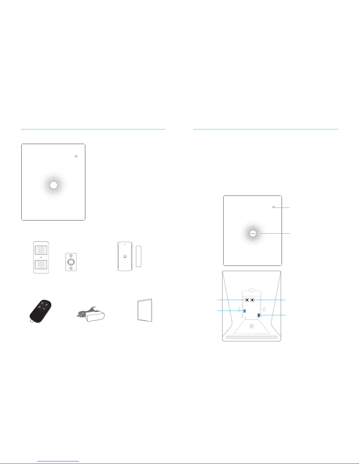
Packing List
1x AW1 Control Panel
status
1x P910 Pet Friendly PIR Motion Sensor 1xM102 Door/ Window Sensor
2x RC80 Remote Control 1x Power Adapter 1x User Manual
Control Panel
All Sensors are wirelessly linked to the Control Panel.
In the event of alarm activation, for example when a Sensor is triggered, a push
notification will automatically be sent to all registered users
The system can be controlled and monitored both on-site using the Remote Control
supplied and remotely from anywhere in the world, with the FREE iOS and Android
Apps.
The system can easily be expanded to include up to: 30 Wireless Sensors and 10
Remote Controls.
WiFi Indicator
Status Indicator
Network Configuration
Power Switch
AC Adapter Jack
Learn Button
3 4
LED Indication
WiFi Indicator
(Blue)
Steady On Connected with Router
One ash per second
Searching for a network or disconnected from
the Router
Off
1) Initialization (the Control Panel beeps every
3 seconds): lasts for up to 30 seconds after
power up
2) The Power Adapter is not plugged in
Status
Indicator
(Red, Blue
and Green)
Steady On Stable WiFi connection
Red System is Armed
Blue System is in Home Mode (Part Arm)
Green System is Disarmed
One ash per second disconnected from the Router
Three ashes per
second
Alarm condition
Functionality of Buttons behind the Back Cover
Learn Used to pair an accessory with the Control Panel
WiFi Used to pair the Control Panel with the Router
On/off Power Switch
Note: The Control Panel must be plugged in to the Power Adapter in order to maintain the WiFi
connection.
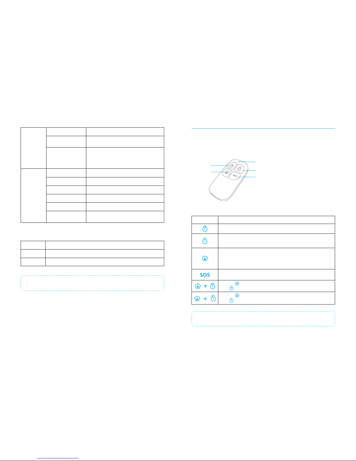
Remote Control
The Remote Control can be used to arm, part arm or disarm the system, and trigger
an emergency alarm (SOS).
Status Indicator
Disarm
Arm
Home Arm
(Part Arm)
SOS button
Button System Status
All Sensors will be armed. This mode is for use when the property is unoccupied.
The System will be Disarmed, no Sensors will be triggered.
Note: When set to ‘Disarm’, Fire, Smoke, and Gas Leakage Sensors will remain
active as they are factory set to ‘24 Hour Zone’
Sensors which are set to the Home Zone will not be Armed. All other Sensors
will be Armed. This mode allows for selected Sensors (for example, front/back
door(s) to be Armed, allowing the occupier freedom of movement within the
property.
The SOS Panic Button will trigger an ‘emergency’ alert notication to registered
users regardless of the Control Panel mode.
Press the [ ] button. After the indicator on the remote control blinks once,
press [ ] button within 3 seconds to mutely arm the system.
Press the [ ] button. After the indicator on the remote control blinks once,
press [ ] button within 3 seconds to mutely disarm the system.
Note: To turn off the arm/disarm tone permanently, open the AW1 Alarm App, go to ‘Internal
Siren'.

5 6
Door/ Window Sensor
Door/ Window Sensors are set to ‘Normal Zone’ by default and are ideal for
protecting entry/exit points such as front and back doors and windows. When
the system is Armed, should a Sensor be triggered (Magnet separated from the
Magnetic Sensor), a push notication showing the named Sensor will automatically
be sent to the registered users and the Control Panel Internal Siren will sound
immediately.
Triggers
when > 1cm
LED blinks once
Tamper Switch
The Tamper Switch (small black button underneath the back cover) will activate an
alarm condition if an unauthorized attempt is made to remove the Sensor from its
installed location.
Low Battery Indication
If the LED indicator ashes once per 3 second, please replace battery.
Pet Friendly PIR Motion Sensor
The Motion Sensor is designed for use on interior walls and is set to Home Mode
by default. Whenever the Sensor detects movement (while the alarm is armed) you
will receive a push alert notication showing the name of the Sensor that has been
triggered and the Control Panel Internal Siren will sound immediately.
LED flashes once
when movement
is detected
Tamper Switch
The Tamper Switch (a black button with a silver spring at the top, located inside this
Sensor) is used to indicate an unauthorized attempt to remove its cover.
Whenever this button is released, it will trigger an alarm and the push alert will
notify you which Sensor has been triggered on tamper.
Low Battery Indication
If the LED indicator blinks once per 3 second, the battery must be replaced.
Working Mode
Test Mode
The Sensor enters a 1 minute settling down period on power up, thereafter entering
into Test Mode. In Test Mode, the Sensor detects movement every 10 seconds and
emits an alarm signal every time movement is detected. Test Mode will remain
active for 3 minutes, thereafter entering into Power Saving Mode.
Note: You may also enter Test Mode by pressing the Test Button at the back of the Sensor.
Power Saving Mode
If the Sensor detects movement twice within 3 minutes the Sensor will automatically
enter into Sleep Mode and no movement will be detected. The Sensor will leave
Sleep Mode after a 3 minute period without any movement.
7 8
Sleep after detecting human movement twice.
Case 1:
Initial start and then arm.
3 minutes later
No human movement within 3 minutes
Switch from sleep to arm.
Case 2:
Press the test button and then arm.
Pairing New Accessories to the Control Panel
There are two ways of pairing Accessories to the Control Panel – manually and via
App.
Manual Pairing
To pair Accessories manually please follow the instructions below:
Remote Control and Sensors:
1. Press the Learn button at the back of the Control Panel
2. Press any button on the Remote Control or trigger the Sensor
Please note that pressing the Tamper Switch instead of triggering the Sensor will
register it as a 24 Hour Zone.
(Optional Accessory) Wireless Siren:
1. Press the Learn Button on the Siren
2. Arm the Control Panel via the App
Pairing from the App
To pair the Accessories via App, open the AW1 Alarm App, go to ‘Edit Accessories’
and follow the instructions on the screen.
WiFi Setup
Step One: Download the App
The App can be downloaded from the App Store or Google Play by searching for
“AW1 Alarm”.
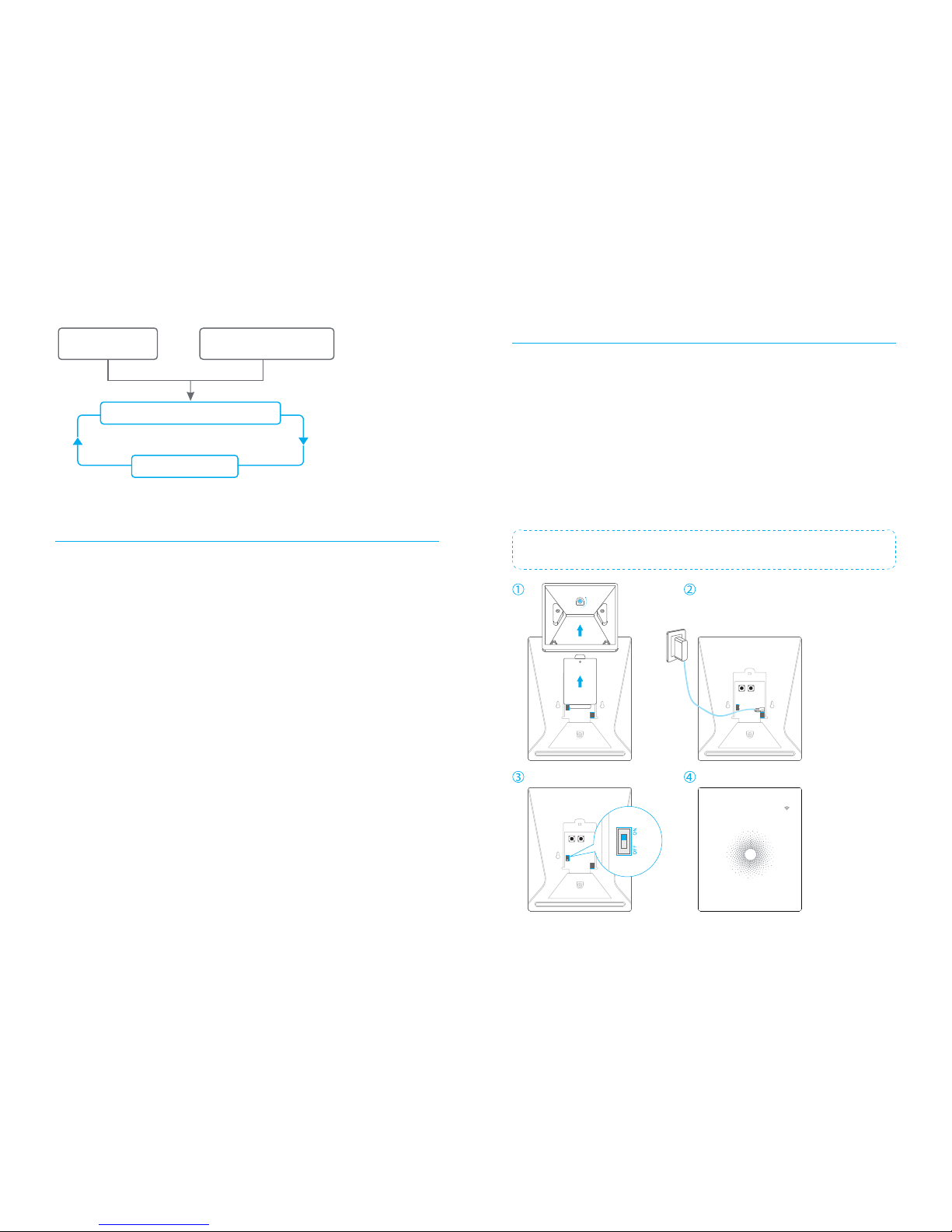
Step Two: Power On
1. Remove the back cover from the Control Panel.
2. Connect the Power Adapter.
3. Set the Power Switch to “ON”.
4. Wait until the WiFi Indicator starts to blink (approx. 30 seconds)
Note: The Control Panel will emit a short ‘beep’ every 3 seconds when powered up. After 30
seconds there will be a long ‘beep’ to conrm that the Panel is ready for use.
status
 Loading...