

Page 1

TM
MigmaDVR
Version 1.5
UserGuide
November 2009
MigmaDVR™ User Guide (Version 1.5)
i
Page 2
Contacts
@
http://www.migmasys.com/MigmaDVR.html Web
Technical support and general
information
Sales
508-660-0328
508-660-0288 Fax
Phone
Migma Systems, Inc.
1600 Providence Highway
Walpole, MA 02081
Mail
Information in this document is subject to change without notice. Companies, names and data used in
examples herein are fictitious unless otherwise noted. Migma Systems, Inc. does not endorse or approve
the use of any of the product names or trademarks appearing in this document.
Permission is granted to copy this document, at no charge and in its entirety, provided that the copies are
not used for commercial advantage, that the source is cited and that the present copyright notice is included
in all copies, so that the recipients of such copies are equally bound to abide by the present conditions. Prior
written permission is required for any commercial use of this document, in completely or in part, and for
any partial reproduction of the contents of this document exceeding 50 lines of up to 80 characters, or
equivalent. The title page, table of contents and index, if any, are not consid ered to b e part of the document
for the purposes of this copyright notice, and can be fr eely re moved if present.
The purpose of this copyright is to protect your right to make free copies of this manual for your friends
and colleagues, to prevent publishers from using it for commercial advantage, and to prevent ill-meaning
people from altering the meaning of the document by changing or removing a few paragraphs.
Copyright © 2002 – 2010
Migma Systems, Inc. All Rights Reserved
MigmaDVR™ User Guide (Version 1.5)
ii
Page 3

Table of Contents
Contacts .............................................................................................................................ii
Table of Contents.............................................................................................................iii
1 About MigmaDVRTM.............................................................................................1-1
2 Package Information..............................................................................................2-1
2.1 Hardware.........................................................................................................................................2-1
2.2 Software........................................................................................................................................... 2-1
3 Hardware Installation............................................................................................3-1
3.1 IR LED Camera Installation ......................................................................................................... 3-1
3.2 Video Capture Card Installation................................................................................................... 3-1
3.3 Video Cable Wiring........................................................................................................................ 3-1
4 Software Installation.............................................................................................4-1
4.1 Windows XP Setup......................................................................................................................... 4-1
4.2 Windows Vista Setup......................................................................................................................4-3
4.3 Windows 7 Setup.............................................................................................................................4-5
5 Starting MigmaDVRTM..........................................................................................5-1
6 Video Camera Configuration................................................................................6-1
7 IP Cameras..............................................................................................................7-1
8 Video Analytical Cueing........................................................................................8-1
8.1 Detection Zone Configuration.......................................................................................................8-1
8.2 Detection Sensitivity ....................................................................................................................... 8-2
8.3 Daily Email Notification.................................................................................................................8-2
9 Image View..............................................................................................................9-1
10 Network Streaming ..............................................................................................10-1
11 Viewing Saved Video Files...................................................................................11-1
MigmaDVR™ User Guide (Version 1.5)
iii
Page 4

1 About MigmaDVR
MigmaDVR
surveillance cameras and one desktop computer. It consists of MigmaDVR
surveillance software, indoor/outdoor IR LED cameras, and multi-channel video capture
card. Video cable and desktop computer are not included.
MigmaDVR
(10 fps for each camera). It also supports the synchronous video compression and
network connectivity over Internet. With the sophisticated analytical video cueing
technologies, video images are recorded only when the objects of interest are detected,
making it possible to store over one year worth of detection images in a typical desktop
computer hard drive, instead of three months as most commercial DVR systems do. With
add-on tools, MigmaDVR
videos and condense the search results in one unified video file. MigmaDVR
operate without any user interactions, 24/7. It is an ideal surveillance system for banks,
office buildings, shopping malls, hospitals, schools, etc.
TM
is a security surveillance system using up to eight high-resolution IR LED
TM
can support up to eight surveillance cameras, operating in near real-time
TM
TM
can perform the intelligent search over all stored detection
TM
TM
can
MigmaDVR™ User Guide (Version 1.5)
1-1
Page 5
2 Package Information
The MigmaDVRTM is made of both hardware components and software program. In this
section, we will describe each component in the package.
2.1 Hardware
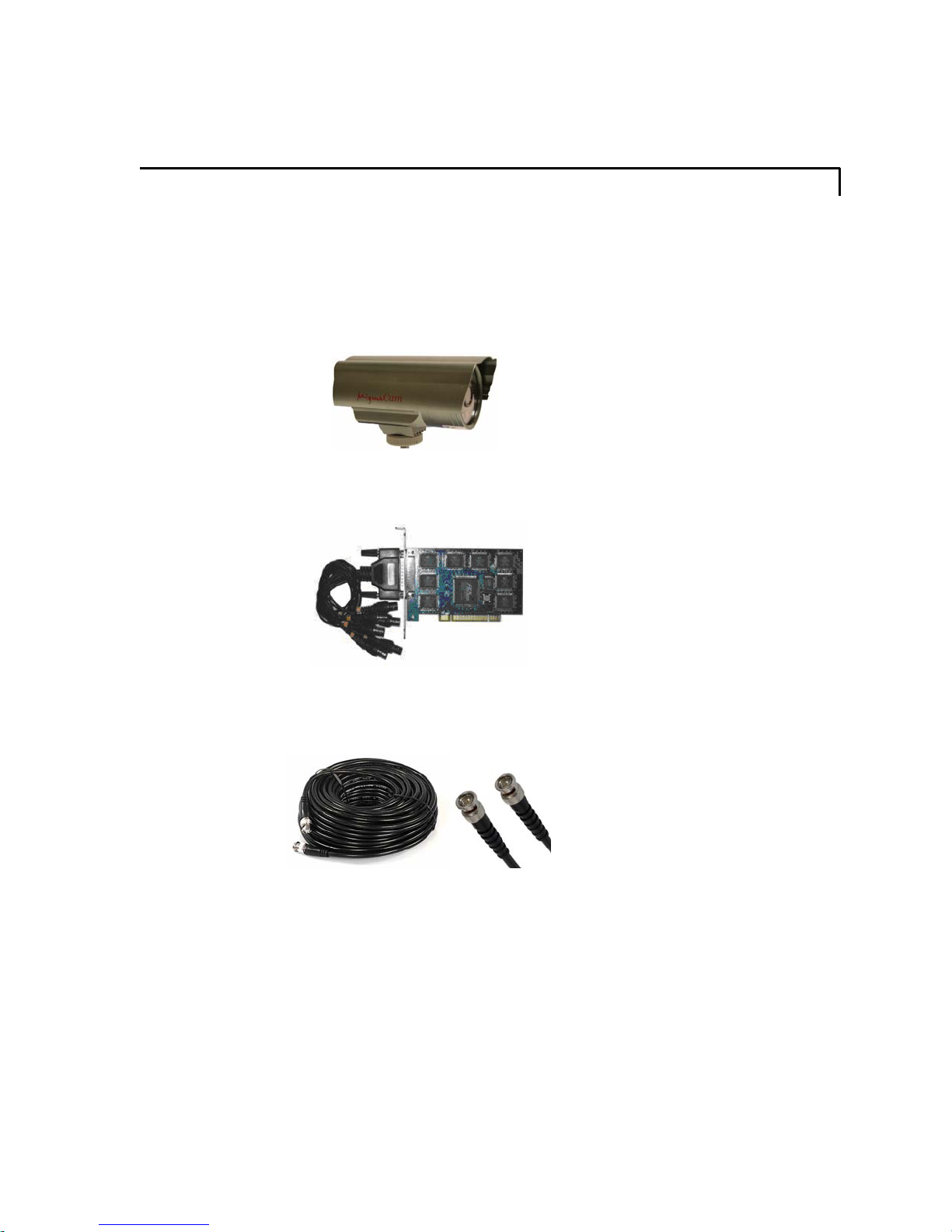
(1) Indoor/outdoor high-resolution IR LED cameras (up to 8)
(2) High quality eight-channel video capture card (1)
To make MigmaDVR
connectors together with a typical desktop computer. It is recommended that RG-59
video cable and its connectors should be used.
A desktop computer is required to host the surveillance software application and a
monitor (optional), if desired, could be used to view the live images. For the desktop
computer, the minimum requirement is 2.66 GHz dual-core CPU, 2GB of RAM,
Windows 7, Windows Vista or XP. The minimum screen resolution of monitor should be
1152×864 pixels. MigmaDVR
TM
operational, the user is expected to have video cables and related
TM
can operate without any monitor.
2.2 Software
The MigmaDVR
in MigmaDVR
TM
software application, device drivers and this User Guide are included
TM
installation CD.
MigmaDVR™ User Guide (Version 1.5)
2-1
Page 6
3 Hardware Installation
3.1 IR LED Camera Installation
The user should first mount the IR LED cameras at the desired places. Depending on the
security monitoring purpose, the cameras can be installed either indoor or outdoor.
3.2 Video Capture Card Installation
The user needs to first install the eight-channel video capture card (included) in the
desktop computer. Please follow the following steps for its installation.
1. Shut down the computer
2. Unplug the power cord
3. Disconnect all the connected devices (if any)
4. Open the computer enclosure
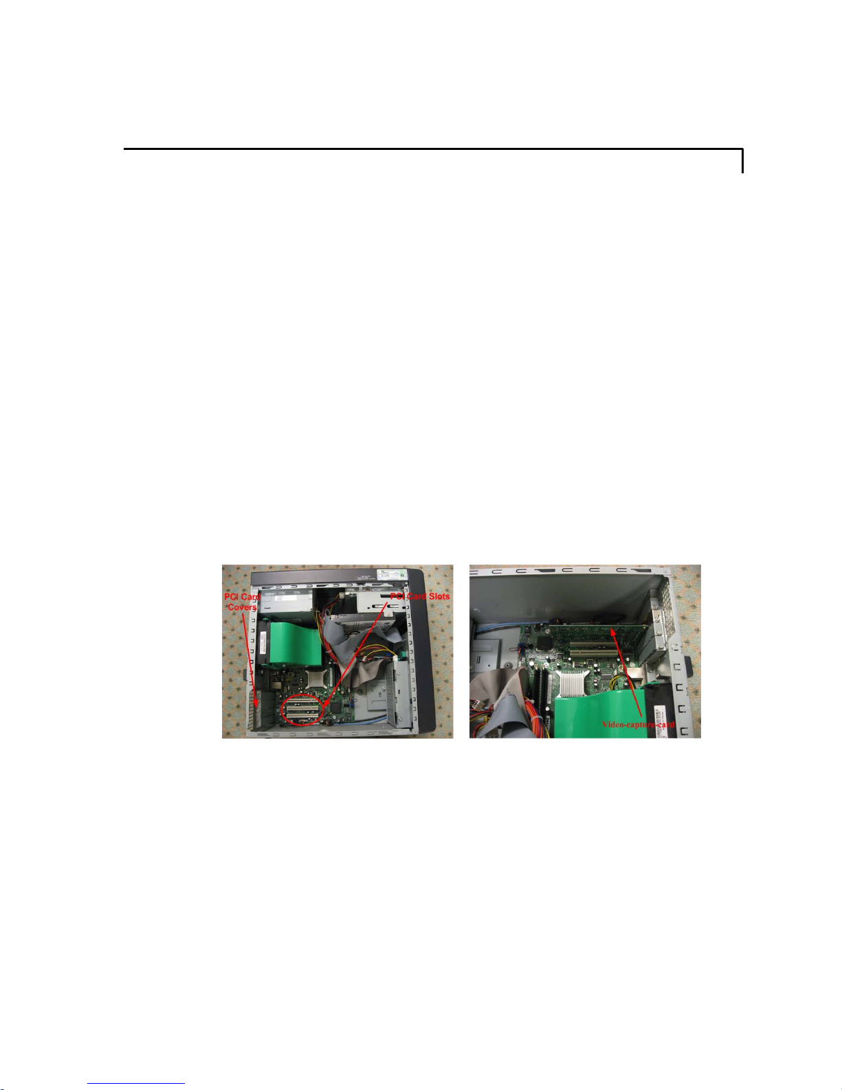
5. Select one of the free PCI card slots (see Figure 3-1 for reference)
6. Firmly insert the video capture card to one free PCI slot and secure it (see Figure
3-2 for reference)
7. Close the computer enclosure
8. Connect all the devices previously connected to the computer
9. Plug in the power cord
10. Follow “Driver Installation” in Section 4 to install the drivers.
Figure 3-1: Free PCI slots. Figure 3-2: Firmly insert video capture card.
3.3 Video Cable Wiring
After mounting the cameras using brackets (included), the user needs to connect all of the
cameras to the 8-channel video capture card installed on the desktop computer. The user
must connect all of the cameras with their power adapters (included).
MigmaDVR™ User Guide (Version 1.5)
3-1
Page 7
4 Software Installation
In this section, we describe how to install MigmaDVR
Windows Vista and Windows 7.
4.1 Windows XP Setup
4.1.1 Video Capture Card Driver Installation
If it is the first time installing the video capture card to the computer, the user needs to
install its drivers. Before installing the drivers, the video cap ture card must be installed in
the desktop computer (complete “Video Capture Card Installation” in Section 3). Then
follow the following steps to install the driver.
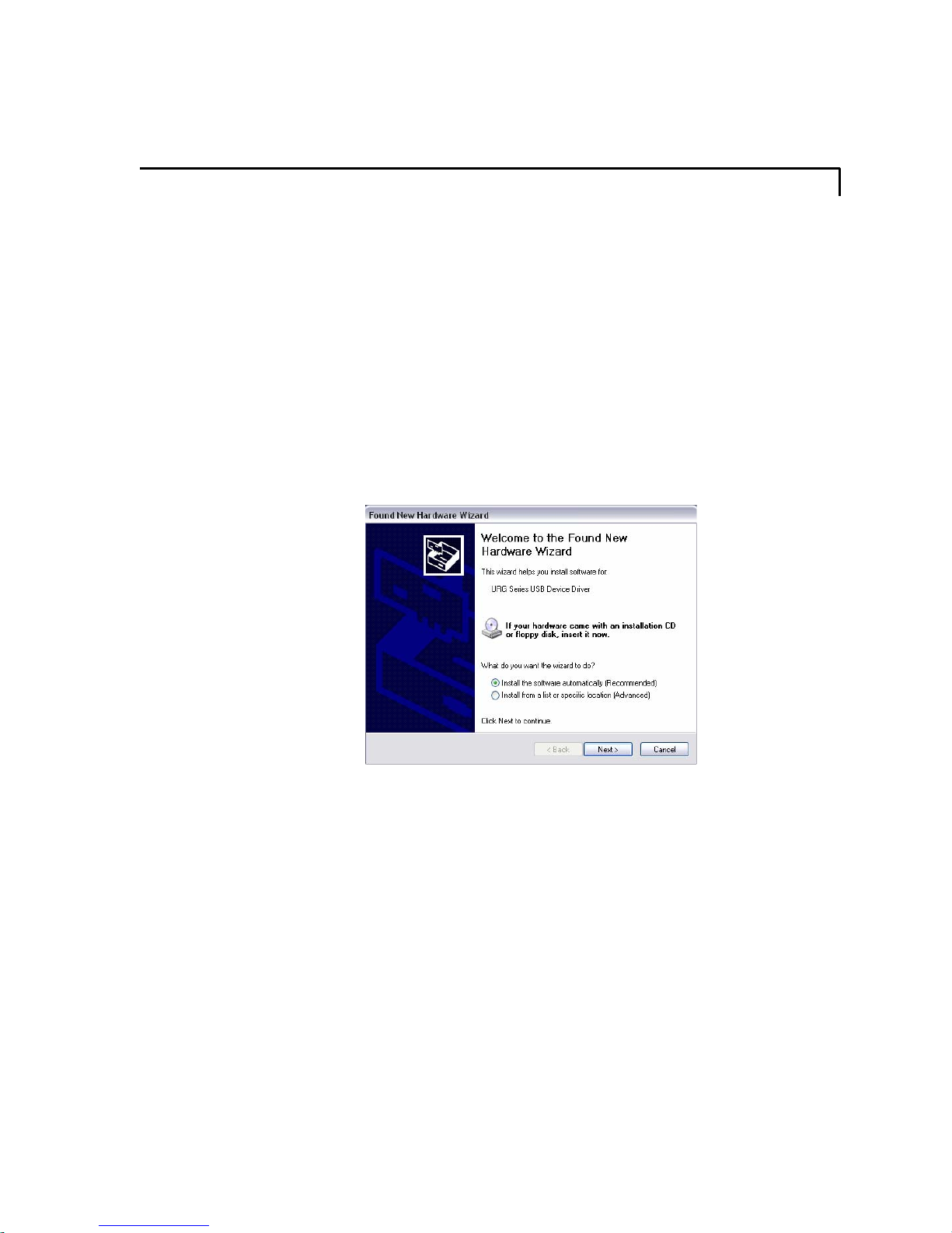
1. Turn on the computer. Once the computer is on, the “Found New Hardware
Wizard” dialog will appear.
TM
software in Windows XP,
Figure 4-1: New hardware found.
TM
2. Insert the MigmaDVR
setup program will automatically start. However, at this point, the user should
choose to exit MigmaDVRTM setup program to allow drivers to be installed first.
3. Choose “Install the software automatically (Recommended)” and click
“Next” on the “Found New Hardware Wizard” dialog box.
4. Click “Continue Anyway”.
MigmaDVR™ User Guide (Version 1.5)
installation CD into CD-ROM or DVD drive. The
4-1
Page 8

Figure 4-2: Driver installation window.
5. Click “Finish” to complete the installation.
6. Since the video capture card has 8 channels and each channel needs 4 different
drivers, after one driver is installed, the “Welcome to Found New Hardware
Wizard” dialog will appear again.
The user must repeat Steps 3 – 5 multiple
times until all of the required drivers are installed successfully.
7. Once all of the drivers are installed, the “Found New Hardware Wizard”
dialog will no longer appear again. The “Device Manager” panel (Start Æ
Settings Æ Control Panel Æ System Æ Hardware Æ Device Manager) can
be used to see all drivers installed (see Figure 4-3 for reference).
Figure 4-3: Device manager window.
4.1.2 MigmaDVR
Insert MigmaDVR
will automatically start. If not, please go to the CD-ROM or DVD drive directory and
double-click on “setup.exe”. Follow the steps shown subsequently and finish the
installation.
4.1.3 MigmaDVR
MigmaDVR™ User Guide (Version 1.5)
TM
Software Installation
TM
installation CD into CD-ROM or DVD drive. The setup program
TM
Software Uninstallation\Reinstallation
4-2
Page 9
If the user needs to uninstall MigmaDVR
TM
software, please go to Start Æ Settings Æ
Control Panel Æ Add or Remove Programs, select “MigmaDVR” and click
“Remove”. Although Windows uninstallation program will not remove the saved
surveillance video files, user is strongly recommended to backup the data to a safe place
before uninstalling MigmaDVR
TM
. If the user prefers to reinstall the MigmaDVRTM
software, all of the surveillance video files stored previously (if not deleted manually)
will remain in the same folders.
4.2 Windows Vista Setup
4.2.1 Driver Installation
If it is the first time installing the video capture card to the computer, the user needs to
install its drivers. Before installing the drivers, the video cap ture card must be installed in
the computer (please complete “Video Capture Card Installation” in Section 3). Then
follow the following steps.
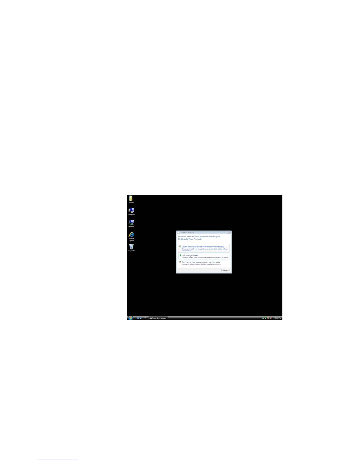
1. Turn on the computer. Once the computer is on, the “Found New Hardware”
dialog will appear (see Figure 4-4 for reference).
Figure 4-4: New hardware is found.
2. Insert MigmaDVR
program will automatically start. However, at this point, the user should choose
to exit MigmaDVRTM setup program to allow drivers to be installed first.
3. Click “Locate and install driver software (recommended)”, the “Found New
Hardware – Multimedia Video Controller” will appear. The user can also
click “Driver Software Installation” icon in the system tray to see the
installation status, as shown in Figure 4-5. Then Click “Next”.
MigmaDVR™ User Guide (Version 1.5)
TM
installation CD into CD-ROM or DVD drive. The setup
4-3
Page 10
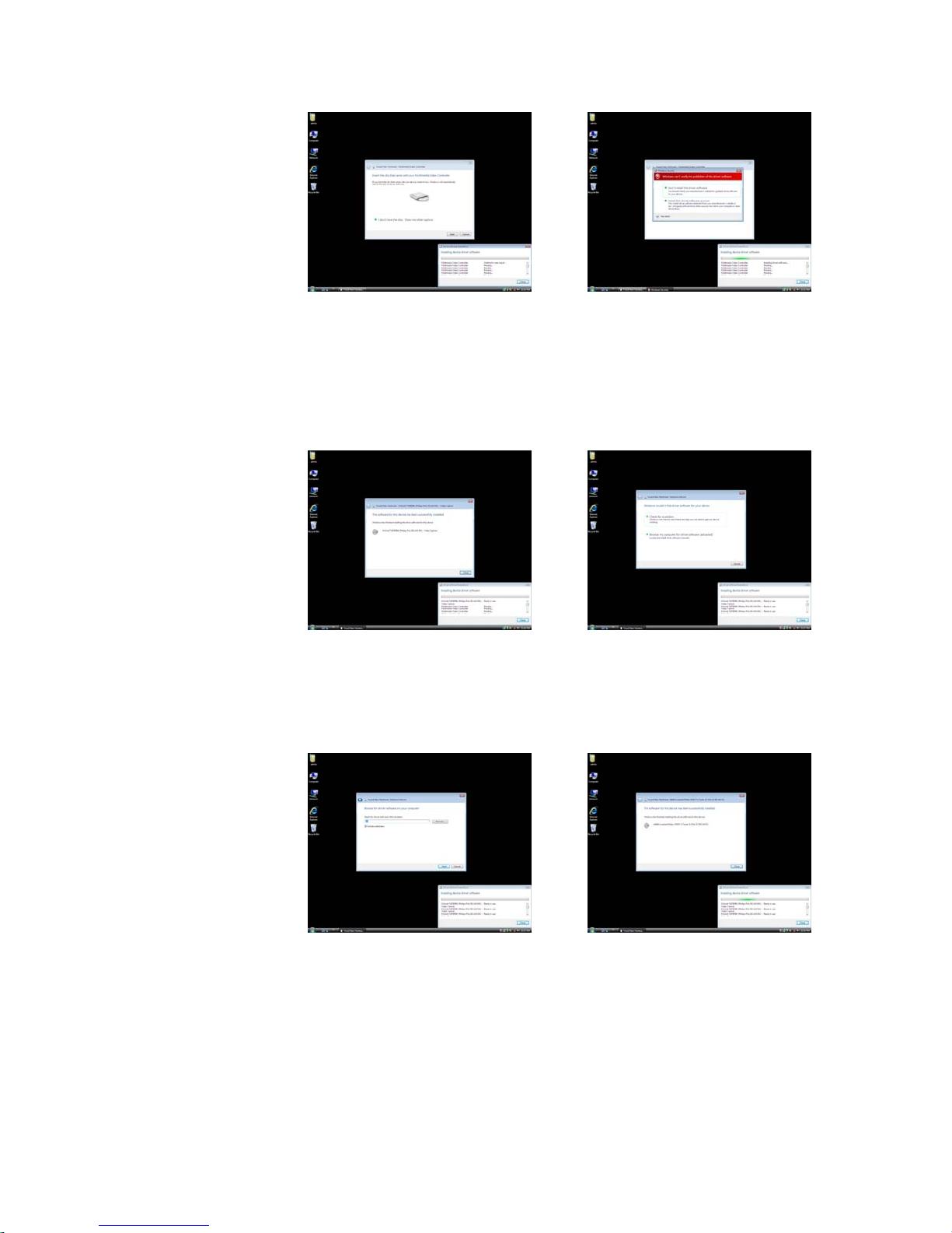
Figure 4-5: Installation status. Figure 4-6: Installation driver.
4. Click “Install this software anyway”, as shown in Figure 4-6 above.
5. When the installation is finished, click “Close”, as shown in Figure 4-7 for
reference. At this point, Windows Vista will automatically install the rest of the
Multimedia Video Controller drivers. The user can check the status in the
“Driver Software Installation” window.
Figure 4-7: Finish driver installation. Figure 4-8: New device is found.
6. After a short period, the “Found New Hardware – Unknown Device” dialog
box will appear, as shown in Figure 4-8 above. Click “Browse my computer
for driver software (advanced)”. Browse to the CD-ROM or DVD drive
directory, and then click “Next”, as shown in Figure 4-9.
Figure 4-9: Browse drives. Figure 4-10: Finish driver installation.
7. Click “Install this software anyway”. Then click “Close”, as shown in Figure
4-10 above.
8. At this point, the “Found New Hardware – Unknown Device” dialog box will
appear one more time. Follow Steps 6-7 to finish.
9. Once all of the drivers are installed, “Driver Software Installation” window
will appear, as shown in Figure 4-11 for reference. The “Device Manager”
MigmaDVR™ User Guide (Version 1.5)
4-4
Page 11
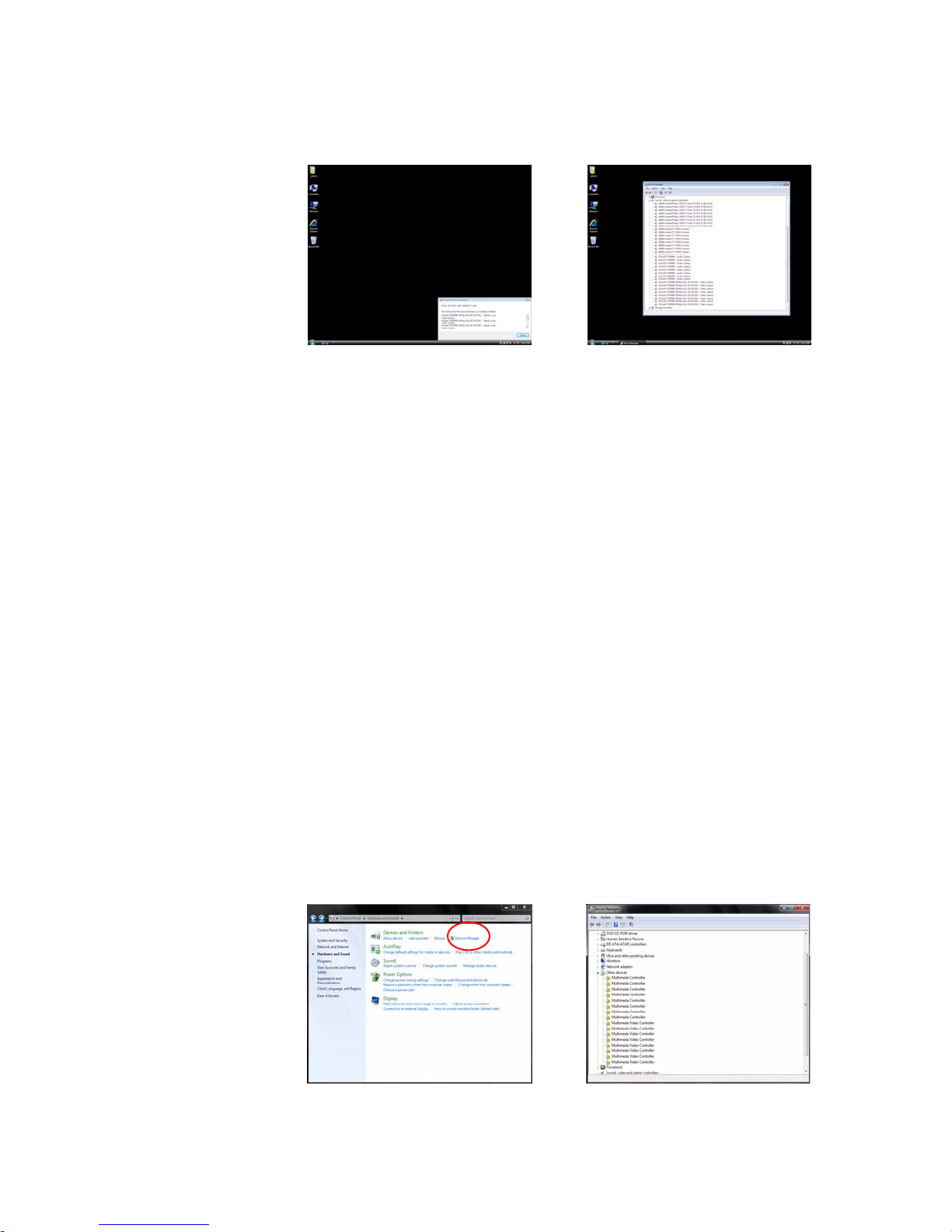
panel (Start Æ Settings Æ Control Panel Æ System Æ Device Manager)
appears (see Figure 4-12 for reference).
Figure 4-11: Driver installation window. Figure 4-12: New driver installed.
4.2.2 MigmaDVR
Insert MigmaDVR
TM
Software Installation
TM
installation CD into CD-ROM or DVD drive. The setup program
will automatically start. If not, please go to CD-ROM or DVD drive directory and click
on “setup.exe”. Follow the steps and finish the setup.
4.2.3 MigmaDVR
If the user prefers to uninstall MigmaDVR
TM
Software Uninstallation\Reinstallation
TM
software, please go to Start Æ Settings Æ
Control Panel Æ Programs and Features, select “MigmaDVR” and click “Uninstall”.
Although Windows uninstallation program will not remove the saved surveillance video
files, user is strongly recommended to backup them to a safe place before uninstalling
MigmaDVR
TM
. If the user prefers to reinstall the MigmaDVRTM software, all of the
surveillance video files stored previously (if not deleted manually) will remain in the
same folders.
4.3 Windows 7 Setup
4.3.1 Driver Installation
If it is the first time to install the video capture card to the computer, the user needs to
install its drivers. Before installing the drivers, the video cap ture card must be installed in
the computer (please complete “Video Capture Card Installation” in Section 3). Then
follow the following steps to install the driver.
1. Turn on the computer. Once the computer is on, go to Start Æ Control Panel
Æ Hardware and Sound Æ Device Manager. The “Device Manger” window
will appear as shown in Figure 4-14.
Figure 4-13: Control Panel. Figure 4-14: Device Manager.
MigmaDVR™ User Guide (Version 1.5)
4-5
Page 12
2. Insert MigmaDVR
program will automatically start. However, at this point, the user should choose
to exit MigmaDVR
TM
installation CD into CD-ROM or DVD drive. The setup
TM
setup program to allow drivers to be installed first.
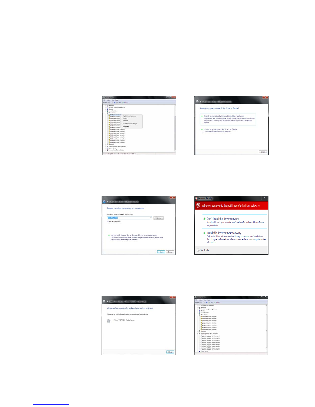
3. Select one “Multimedia Controller” from the “Device Manager” window and
then right click on it. Then choose “Update Driver Software” (shown in Figure
4-15). This will bring out the “Update Driver Software” window (shown in
Figure 4-16).
Figure 4-15: Device Manager. Figure 4-16: Update Driver Software.
4. Select and click on “Browse my computer for driver software” and a window
will appear as shown in Figure 4-17. In this window, click on th e Browse bu tton
and browse to the driver directory, BT848_Driver, located in the MigmaDVR
TM
installation CD and click “Next”.
Figure 4-17: Browse for driver. Figure 4-18: Install driver software.
5. Click “Install this driver software anyway,” as shown in Figure 4-18.
6. Wait until the driver installation is complete and then click “Close”, as shown in
Figure 4-19.
Figure 4-19: Driver installed. Figure 4-20: Multimedia video controller.
MigmaDVR™ User Guide (Version 1.5)
4-6
Page 13
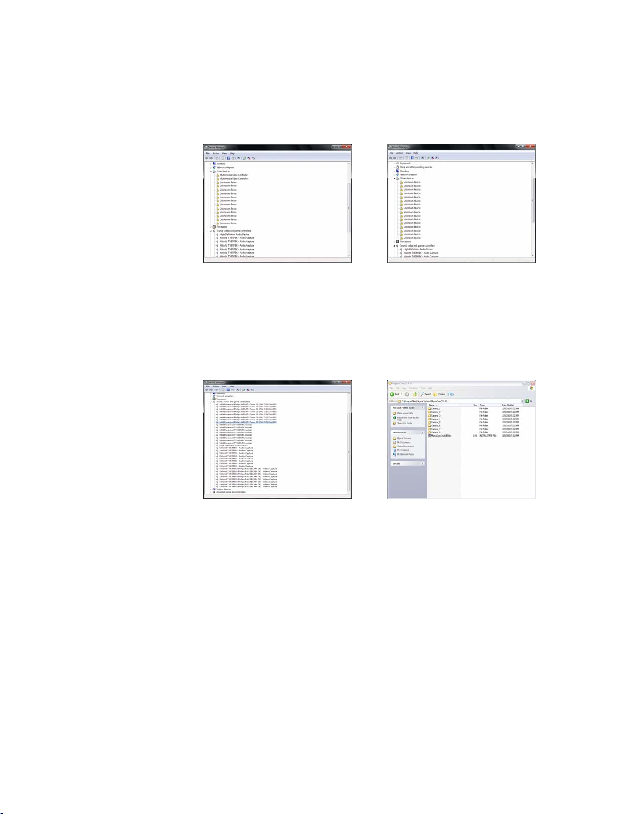
7. Select each “Multimedia Video Controller” from the “Device Manager”
window (shown in Figure 4-20), and similarly repeat Steps 3-6 to install all the
drivers. Note that the device manager will show “Unknown device” as the
drivers are installed for each “Multimedia Video Controller” (shown in Figure
4-21).
Figure 4-21: Unknown device. Figure 4-22: Device Manager.
8. After the driver installation is completed for the “Multimedia Video
Controller”, select an “Unknown device” from the “Device Manager”
window, right click on it and update driver software as explained for Multimedia
Controller in Steps 3-6 to install all the divers (shown in Figure 4-22).
9. Once all the drivers installed, the “Device Manager” window will appear as
shown in Figure 4-23.
Figure 4-23: Drivers installed. Figure 4-24: After uninstallation.
4.3.2 MigmaDVR
Insert MigmaDVR
TM
Software Installation
TM
installation CD into CD-ROM or DVD drive. The setup program
will automatically start. If not, please go to CD-ROM or DVD drive directory and click
on “setup.exe”. Follow the steps and finish the setup.
4.3.3 MigmaDVR
If the user wants to uninstall MigmaDVR
TM
Software Uninstallation\Reinstallation
TM
software, please go to Start Æ Control
Panel Æ Programs Æ Program and Features, select “MigmaDVR” and click
“Uninstall.” Although the uninstallation program will not remove the saved surveillance
video files shown in Figure 4-24 (above), the user is strongly recommended to backup
these files to a safe place before uninstalling MigmaDVR
reinstall the MigmaDVR
TM
software, all of the surv eillance video files stored previously
TM
. If the user prefers to
(if not deleted manually) will remain in the same folders.
MigmaDVR™ User Guide (Version 1.5)
4-7
Page 14
5 Starting MigmaDVR
After installing MigmaDVR
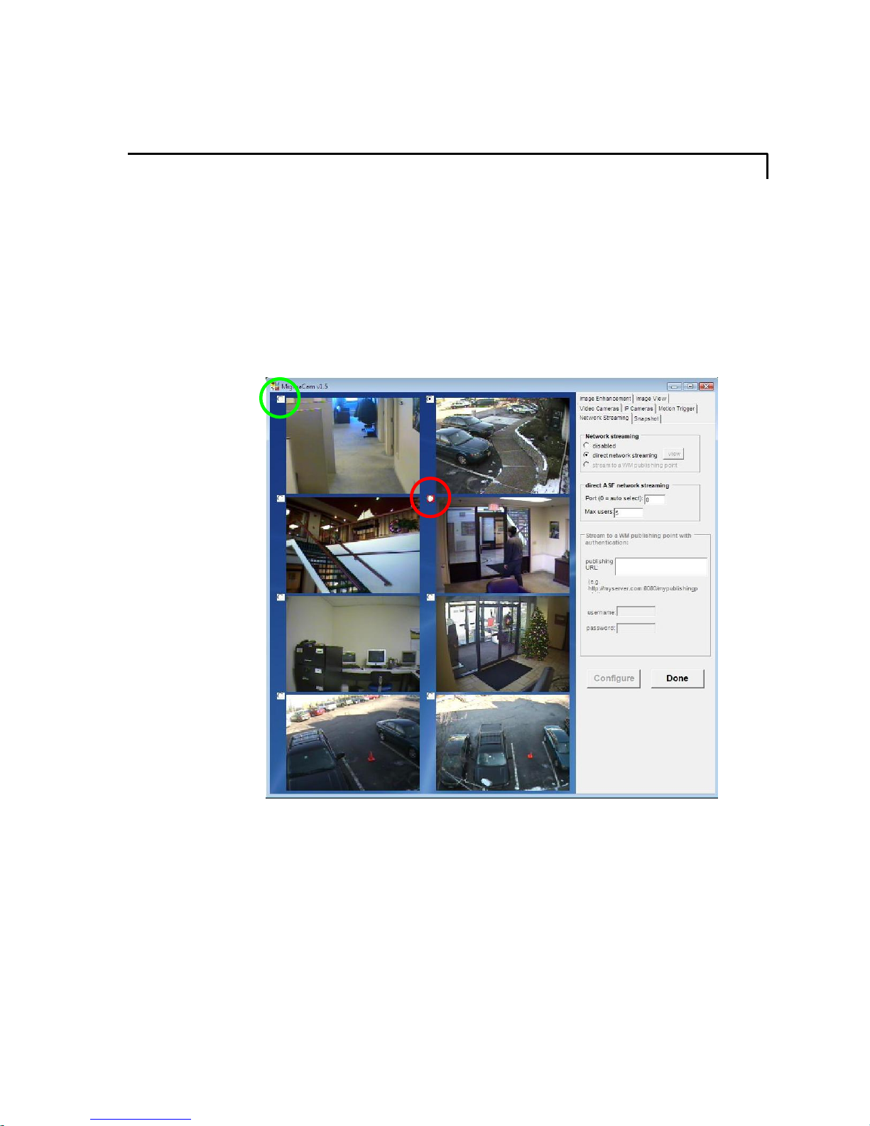
on the desktop of computer to start the surveillance program.
Once MigmaDVR
MigmaDVR
videos from 8 IR LED cameras connected to the system. To choose which camera to
configure, the user can click the radio button on the upper-left corner of each video image
overlay (circled in green). If the radio button on the upper-left corner of a camera image
overlay turns red (circled in red), the related camera has detected objects and images are
being recorded to a movie file automatically.
TM
TM
has started, its main window will appear as shown in Figure 5-1 and
will start performing the surveillance for you. Figure 5-1 shows the live
TM
hardware and software, double click MigmaDVRTM icon
TM
Figure 5-1: MigmaDVRTM main window.
MigmaDVR™ User Guide (Version 1.5)
5-1
Page 15
6 Video Camera Configuration
On the right side of the MigmaDVR
Cameras options will appear.
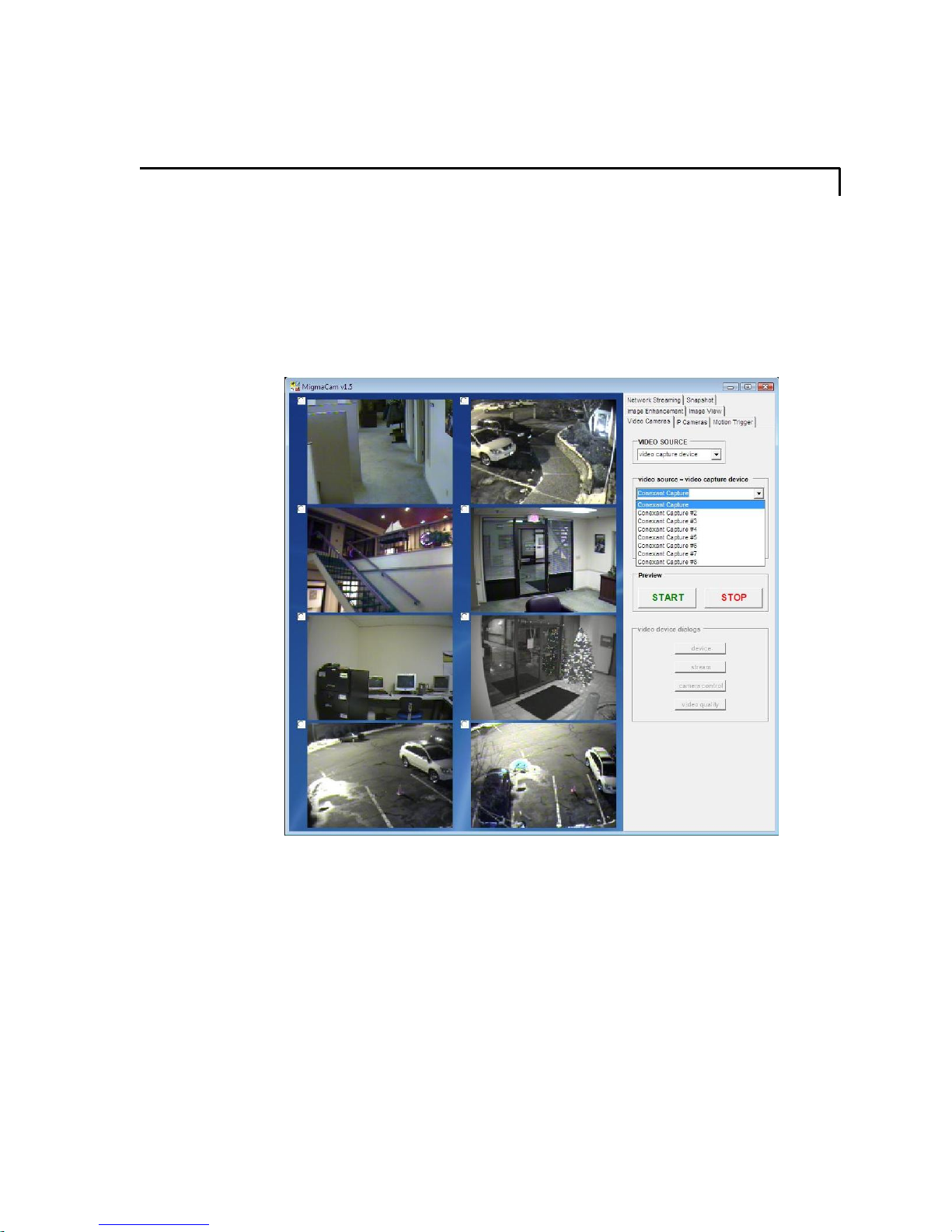
The “Video Source” box will show that the video source is video capture device. The
“Video Capture Device” in “Video Source” drop box indicates the video capture device
associated with each individual camera.
The order of the cameras is given in Figure 6-1. This order is fixed.
12
TM
window, click “Video Cameras” tab. The Video
3
4
5 6
7
Figure 6-1: Video camera orders in MigmaDVRTM.
The Video Camera panel also shows the “video input,” “video size,” “video subtype”
and “analog video standard,” as shown in Figure 6-2.
Click the “Start” button to start the selected camera, and click the “Stop” button to stop
the selected camera from operation.
8
MigmaDVR™ User Guide (Version 1.5)
6-1
Page 16
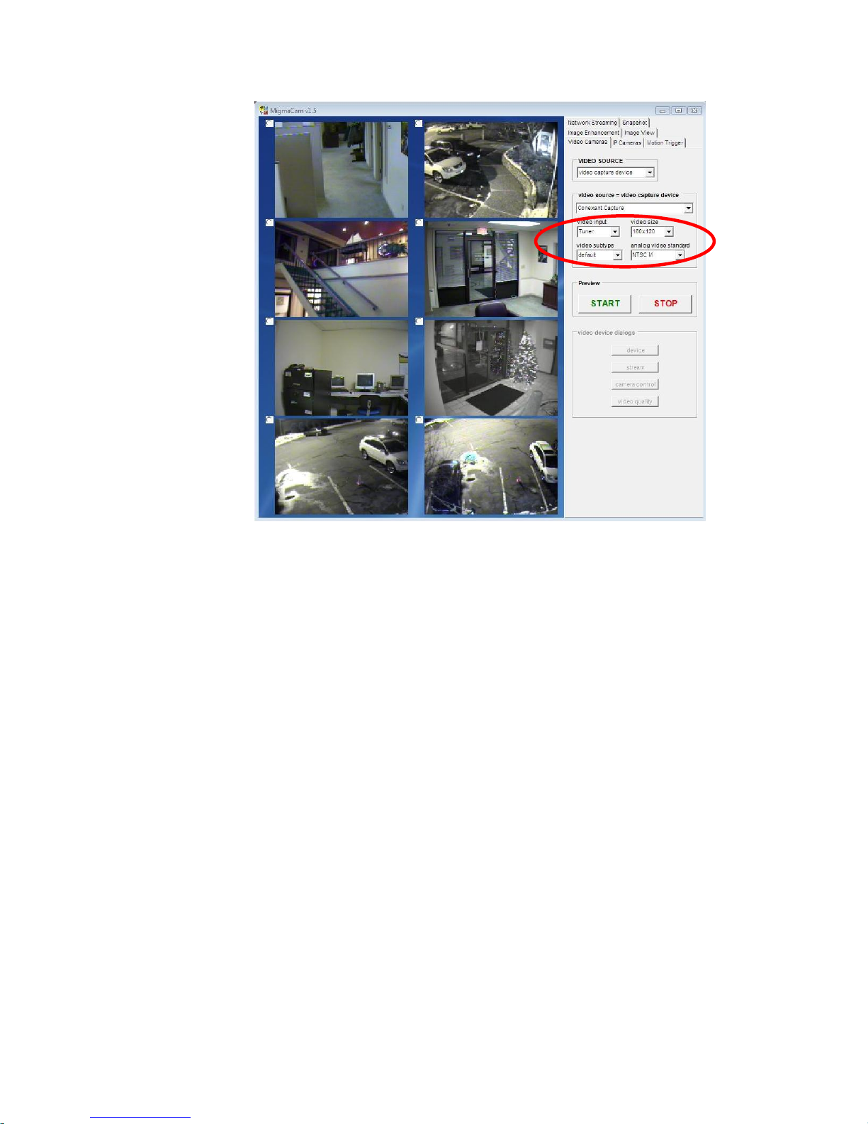
Figure 6-2: Video camera selection
Note: Some disabled buttons are not functional in the current version of MigmaDVR
TM
.
MigmaDVR™ User Guide (Version 1.5)
6-2
Page 17
7 IP Cameras
The MigmaDVRTM can also be configured to use IP camera. Choose a camera panel
where the IP camera images need to be displayed by selecting the radio button next to it.
On the right side of MigmaDVR
options will appear.
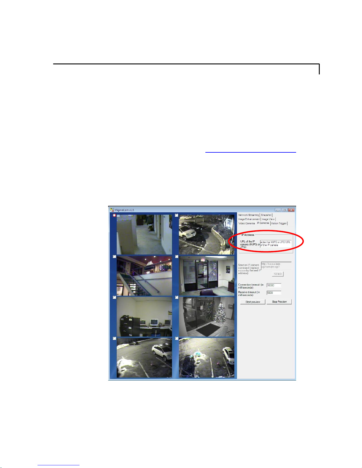
The user can directly connect an IP camera by typing the URL address of the IP camera
in the “URL of the IP camera (MJPG or JPG)” textbox (as shown in Figure 7-1).
Different IP camera manufacturers may have different URL address format. The user can
find the format at IP camera manufacturer’s web site or user guide. For example, the
URL address format of LinkSys IP camera is
x’s represent the IP address. The camera’s IP address can also be found from the network
administrator, or at the network router. In some cases, the IP address could be set by the
IP camera manufacturer and can also be found in the camera’s user manual. The user can
also setup the connection timeout and receiving timeout for the IP camera.
User can start or stop an IP camera by clicking “Start Preview”/”Stop Preview”.
TM
window, click “IP Cameras” tab. The IP Cameras
http://xxx.xxx.xxx.xxx/img/video.asf. The
Figure 7-1: IP camera setting.
Note: Some disabled buttons are not functional in the current version of MigmaDVR
MigmaDVR™ User Guide (Version 1.5)
TM
.
7-1
Page 18
8 V ideo Analytical Cueing
The motion trigger is an important feature of MigmaDVR
sophisticated video analytical cueing technologies. To configure this feature, user needs
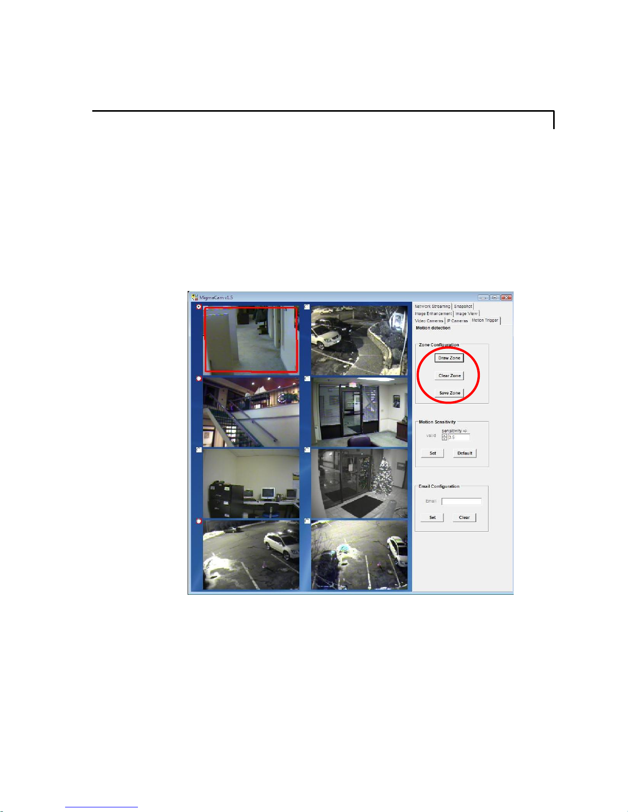
to select the camera of interest. Click on “Motion Trigger” tab. The motion detection
window appears as shown in Figure 8-1.
The detection zone can be adjusted in MigmaDVR
detection zone, and let MigmaDVR
zone. By default, the detection zone covers almost the entire image. By drawing the zone
appropriately, the number of false detections can be greatly reduced. For example, if user
is only interested in detecting people walking through the door, he or she may want to
draw the zone covering the area of door only.
TM
perform the detection only when objects fall in this
TM
. It is based on our
TM
. The user can define his or her own
Figure 8-1: The default detection zone.
8.1 Detection Zone Configuration
To draw a detection zone, click “Draw Zone” button. The current zone will appear. Click
“Clear Zone”, and then start drawing a new zone based on your requirement. The user
only needs to click the four corners of the zone in a clockwise orientation, and the
detection zone will complete automatically. After drawing, please click “Save Zone” to
store the detection zone. The user can also clear a zone to draw a new zone by clicking
“Clear Zone”. After the zone is saved, click the “Video Cameras” tab to make the zone
effective.
MigmaDVR™ User Guide (Version 1.5)
8-1
Page 19
8.2 Detection Sensitivity
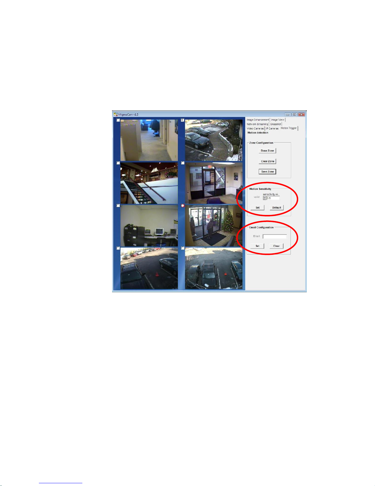
Detection sensitivity is an important parameter that controls how sensitive the detection is
made. Its default value is 3.5, and user can adjust it to obtain the optimal detection results
based on the number of false detections observed. If there are too many false detections,
user can reduce the value of sensitivity. If user prefers to have more detections, h e or she
can make the value of sensitivity larger. The maximum value of sensitivity is 5.0.
Figure 8-2: Adjustment of detection sensitivity.
8.3 Daily Email Notification
MigmaDVR
system operation status. It sends out the daily report at 6 p.m. In the unattended
operation, this email alert can help user know how the surveillance system is performing.
For example, if the hard disk is almost full, the user must backup the detection video files
and delete them to make more disk space available for further operation.
The designation email address can be configured. The user can type in the desired email
address in the “Email Configuration” text field and click “Set” (see Figure 8-2 above).
Internet connection is required for this function.
MigmaDVR™ User Guide (Version 1.5)
TM
also provides email alerts to report the computer hard disk usage and
8-2
Page 20
9 Image V iew
MigmaDVR
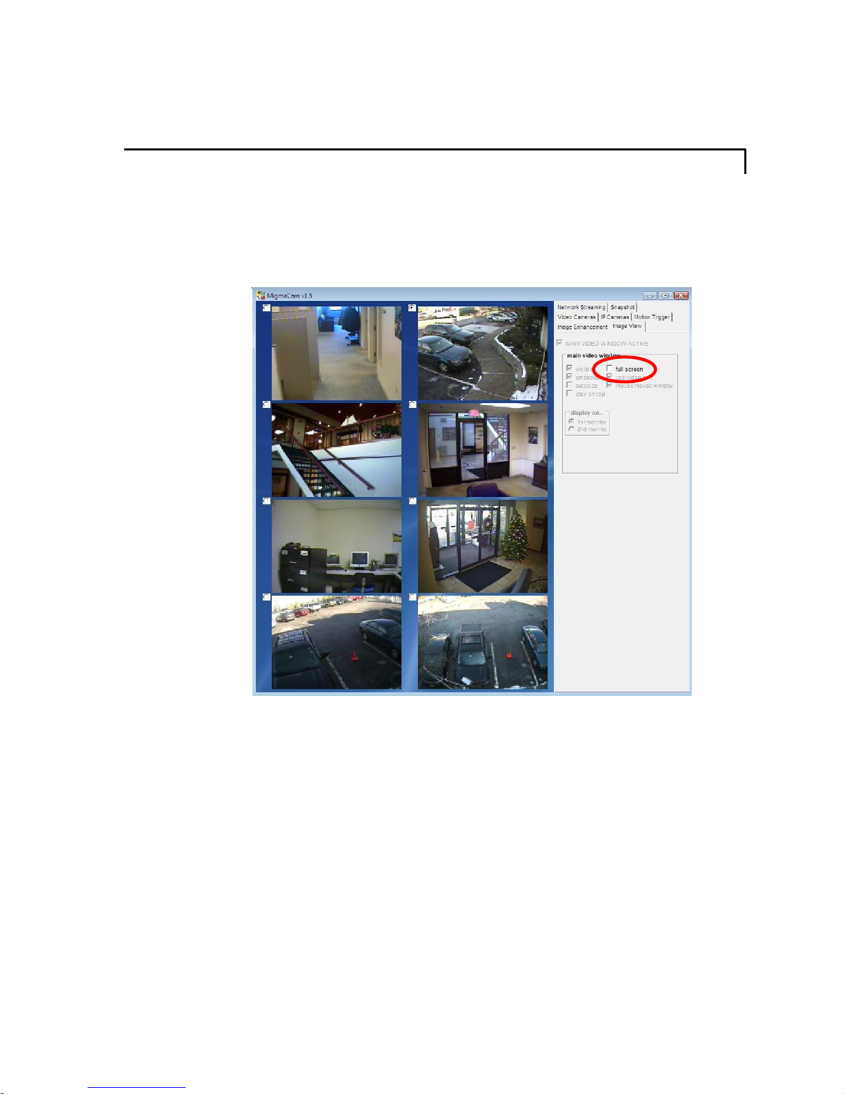
select the camera to be viewed in full screen, then click the “Image View” tab, and
finally check the “full screen” check box (shown in Figure 9-1). To exit the full screen
display, press the “Esc” key on the keyboard.
TM
is capable of displaying individual camera images as full screen. First,
Note: Some disabled buttons are not available in the current version of MigmaDVR
MigmaDVR™ User Guide (Version 1.5)
Figure 9-1: Full screen display selection.
TM
.
9-1
Page 21
10 Network Streaming
The MigmaDVR
the network streaming window. Internet connection is required for this feature.
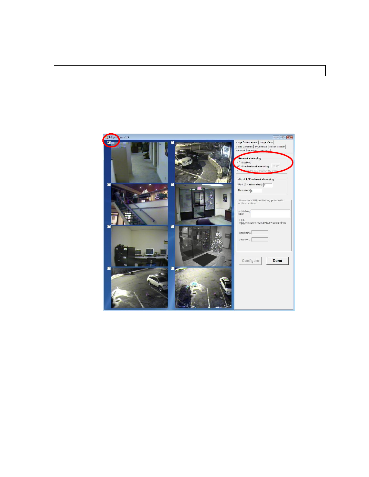
Select the camera that the user plans to use for network streaming, then click “Configure”.
By default, all the cameras are ready for network streaming. The user can disable network
streaming for the selected camera by checking “disabled” (shown in Figure 10-1).
TM
supports the network streaming. Click “Network streaming” tab to open
Figure 10-1: Network streaming setting.
Check “direct network streaming” to enable the network streaming. In order to start
network streaming, some parameters must be configured.
First user needs to decide which Windows port to use and the maximum number of users
allowed for access of network streaming. Type in the port number in “Port (0 = auto
select)” text box and the maximum number of users in the “Max users” text box. For
example, in Figure 10-2, the Windows port 65525 is selected and up to 5 users for the
camera 1 are allowed. If the user plans to stream another camera, first select the camera,
and type in a different Windows port number for that camera. As an example, Windows
port 65526 was selected for camera 2. Please perform these steps for all of the other
cameras.
Click “Done” to finish.
MigmaDVR™ User Guide (Version 1.5)
10-1
Page 22
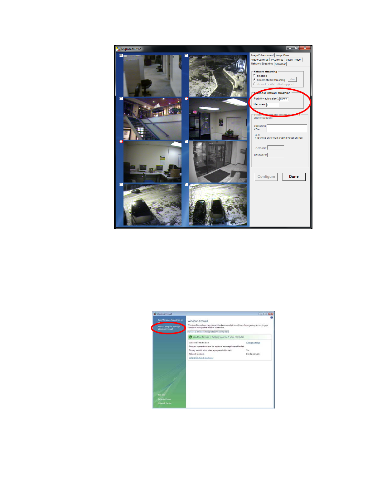
Figure 10-2: Network streaming configuration.
User also needs to open the communication port in the Windows firewall of the desktop
computer where the MigmaDVR
TM
software is installed. Figures 10-3 to 10-7 show how
to open the communication port in Windows.
For Windows Vista
Go to Start Æ Setting Æ Control Panel Æ Windows Firewall, and then click on Allow
a program through Windows Firewall.
When the “Windows Firewall Settings” dialog box appears, click on “Exceptions”, as
shown in Figure10-4.
MigmaDVR™ User Guide (Version 1.5)
Figures 10-3: Open Windows communication port.
10-2
Page 23
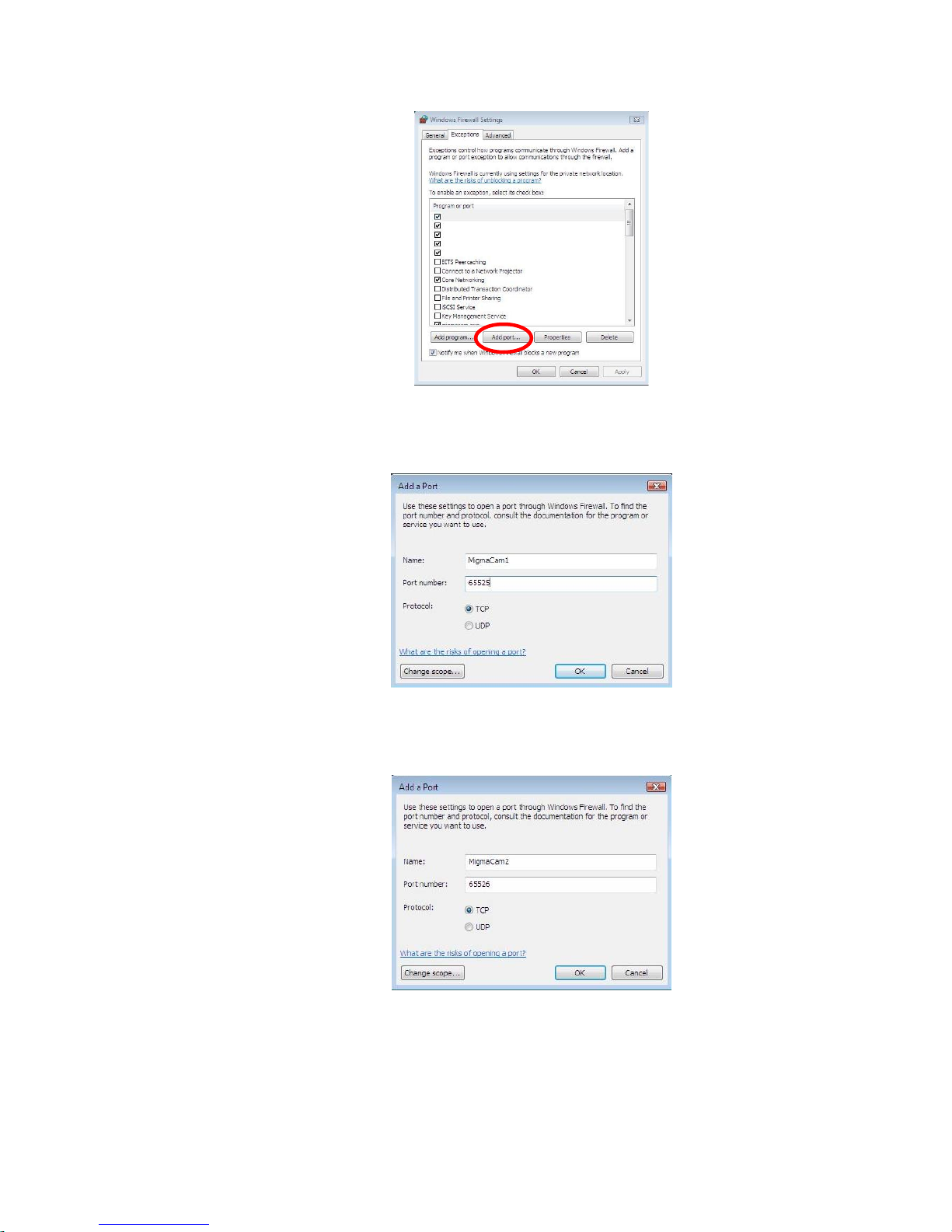
Figures 10-4: Open Windows communication port.
Click “Add Port” button, type the port name, port number and choose “TCP” as the
protocol, and then click “OK”.
To add a port for camera 2, click “Add Port”, type a different port name and port
number.
After creating ports for all of the cameras, the “Windows Firewall Settings” dialog
appears as shown in Figure 10-7.
Figures 10-5: Open Windows communication port.
Figures 10-6: Open Windows communication port.
MigmaDVR™ User Guide (Version 1.5)
10-3
Page 24
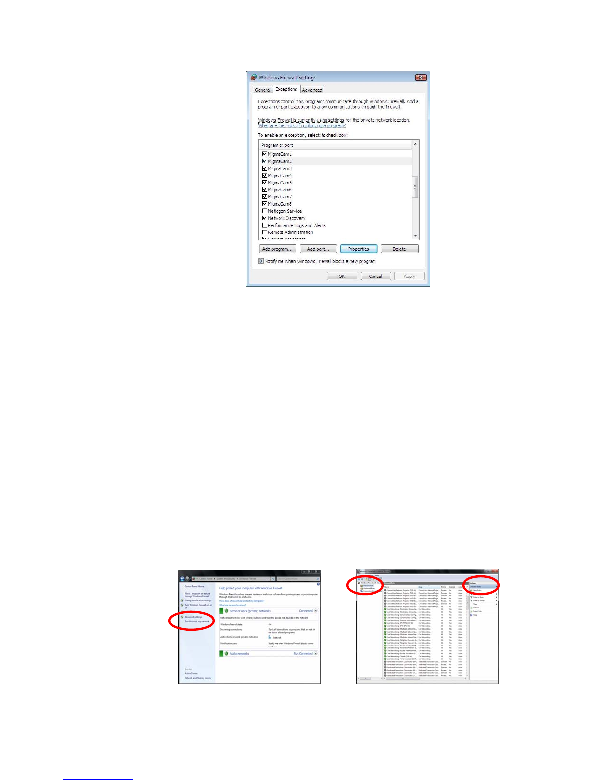
Figures 10-7: Open Windows communication port.
Note: For each camera, the “Name” can be some meaningful text, and the port number
entered in “Port number” text box should be the same as what typed in MigmaDVR
TM
network configuration.
Note: Some disabled buttons are not available in the current version of MigmaDVR
TM
.
For Windows XP
Go to Start Æ Setting Æ Control Panel Æ Windows Firewall, click on Exceptions tab
in the Windows Firewall dialog. Follow the same steps described for Windows Vista.
Note: For each camera, the Name can be some meaningful text, and the port number
entered in Port number text box should be same as what typed in MigmaDVR
TM
network configuration.
Note: Some disabled buttons are not available in the current version of MigmaDVR
TM
.
For Windows 7
Go to Start Æ Control Panel Æ System and Security Æ Windows Firewall Æ
Advanced settings (shown in Figure 10-8), choose Inbound Rules”\ (shown in Figure
10-9).
Figure 10-8: Control panel Figure 10-9: Inbound rules creation.
MigmaDVR™ User Guide (Version 1.5)
10-4
Page 25
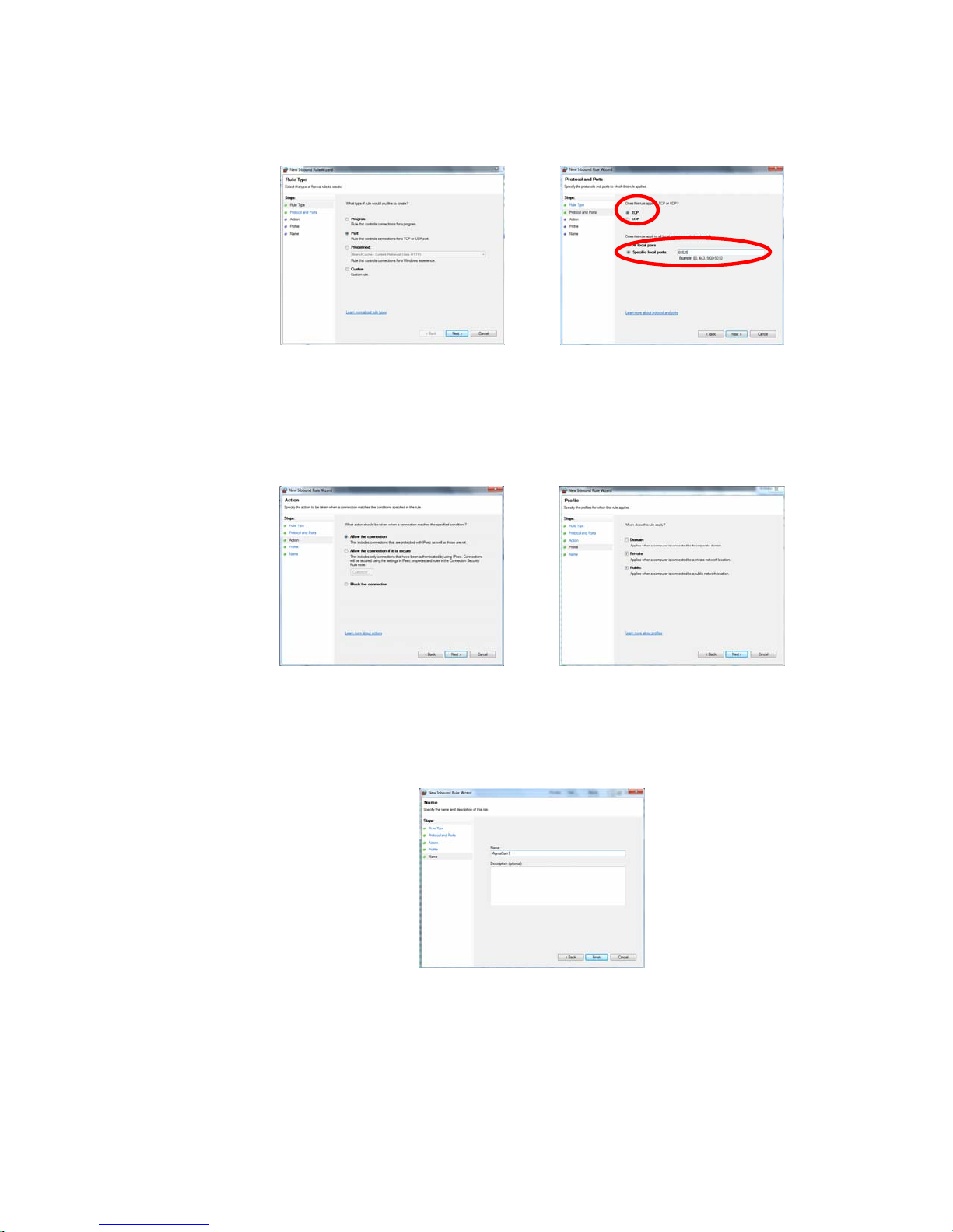
Choose “New Rule…” from the right hand panel (shown in Figure 10-9), and the “New
Inbound Rule Wizard” will appear as shown in Figure 10-10.
Figure 10-10: Create new rule. Figure 10-11: Open communication port.
Select Port (shown in Figure 10-10), and click on Next. Type the port number and
choose TCP as the protocol, and then click Next (as shown in Figure 10-11). For
example, we used 65525 as the port number for camera 1.
Select Allow the connection and click Next (shown in Figure 10-12).
Figure 10-12: Setup connection. Figure 10-13: Port access setup.
Select both Private and Public, and click on Next (shown in Figure 10-13).
Type the name for the rule and click on Finish (shown in Figure 10-14). For example, we
used MigmaCam1 for camera 1.
To add a port for camera 2, click on New Rule… again, type a different port number and
follow all the steps described above (shown in Figures 10-15 and 10-16). For example,
we used 65526 as the port number and MigmaCam2 as the name for camera 2.
MigmaDVR™ User Guide (Version 1.5)
Figure 10-14: Port name setup.
10-5
Page 26
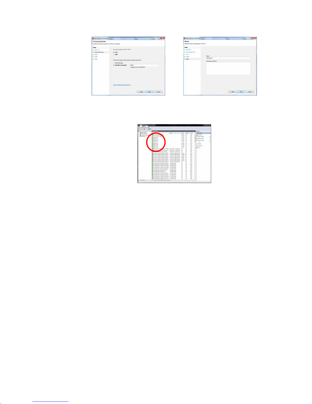
Figure 10-15: Open communication port. Figure 10-16: Port name setup.
After creating ports for all of the cameras, the Inbound Rules window appears as shown
in Figure 10-17.
Figure 10-17: Inbound rules window.
Note: For each camera, the Name can be some meaningful text, and the port number
entered in Port number text box should be same as the port setup using MigmaDVR
TM
network streaming configuration.
Note: Some disabled buttons are not available in the current version of MigmaDVR
TM
.
MigmaDVR™ User Guide (Version 1.5)
10-6
Page 27
11 Viewing Saved Video Files
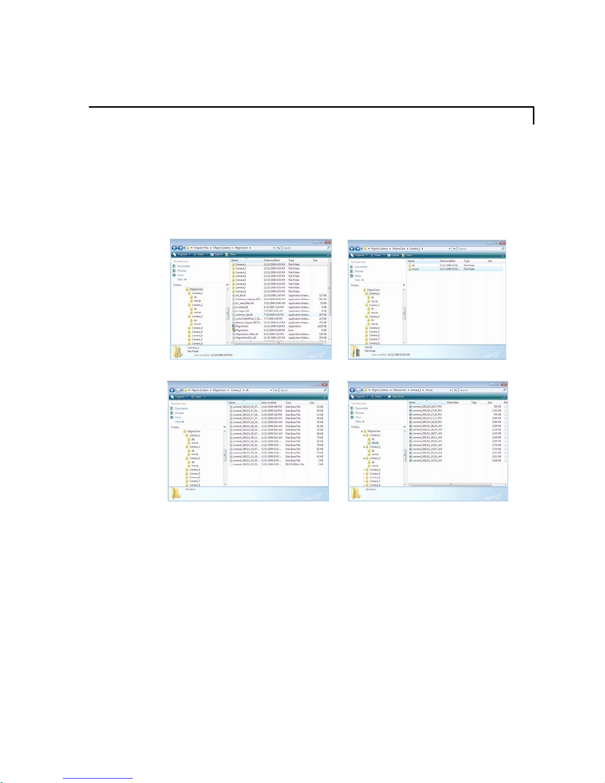
The recorded surveillance video files are stored in the folder wh ere the MigmaDVRTM
software is installed. As shown in Figure 11-1, all the video files are stored in Camera_1,
Camera_2 …, and Camera_8 folders (the names of the folders cannot be changed). In
each camera folder, there are two subfolders – “db” and “movie” (shown in Figure 11-2).
For each movie file in the “movie” folder, there is a corresponding database file in the
“db” folder (shown in Figures 11-3 and 11-4). The naming convention of the movie file
and database file is CameraName_YearMonthDay_Hour_Minute_PM/AM (for example
camera2_091210_21_28_PM). The name encodes the time when the file was created.
Figure 11-1: Camera folders. Figure 11-2: Folders in each camera folder.
Figure 11-3: Detection database files. Figure 11-4: Detection movie files.
A full-length movie file contains exactly 2,000 frames. MigmaDVR
creates a new movie file when the current working movie file reaches 2000 frames. The
current working movie file cannot be viewed until it has 2000 frames. If the user has to
view the current working movie file, he or she must exit the MigmaDVR
The movie files are in the .asf format and can be played in Windows Media Player.
TM
automatically
TM
application.
MigmaDVR™ User Guide (Version 1.5)
11-1
 Loading...