


UNIVERSAL INSTRUCTIONS
BRACELE S S OV AL PO O LS
PLEASEREAD THESE INSTRUCTIONS CAREFULLY AND THOROUGHLY BEFORE
STARTING GROUND PREPARATION AND POOL A SSEM BLY.
DOING SO WILL PREVENT PROBLEMS.
Oval Pool: General informaition -----------------------------------
1) Selection of pool site --------------------------------------------
2) Ground preparation ----------------------------------------------
3) Assembling side structual component -----------------------
4) Drawing pool shape ----------------------------------------------
5) Connecting tension straps --------------------------------------
6) Positioning assembled oval parts -----------------------------
7) Assembling bottom rail ------------------------------------------
8) Installing wall -------------------------------------------------------
9) Build an earth mound(Cove) -----------------------------------
10) Through the wall skimmer --------------------------------------
11) Liner installation ---------------------------------------------------
Please refer to "Assembl e TopSeat , Vertic al and Cover" o f an attached sheet.
12) Filling the pool -----------------------------------------------------
13) Helpful information -----------------------------------------------
14) SAFETY RULES -------------------------------------------------BRACELESS OVAL Parts List -------------------------------------
1
1
2
3
5
7
7
8
8
9
9
9
9
10
10
11
Page.
Meijer.com
Do not start the instal lation of y our pool unless you have
an entire day to finish the work.
Do not try to set up your pool on a windy day.
The wall will be difficult or even impossible to handle.
An average pool needs 2 or 3 people for
installation.
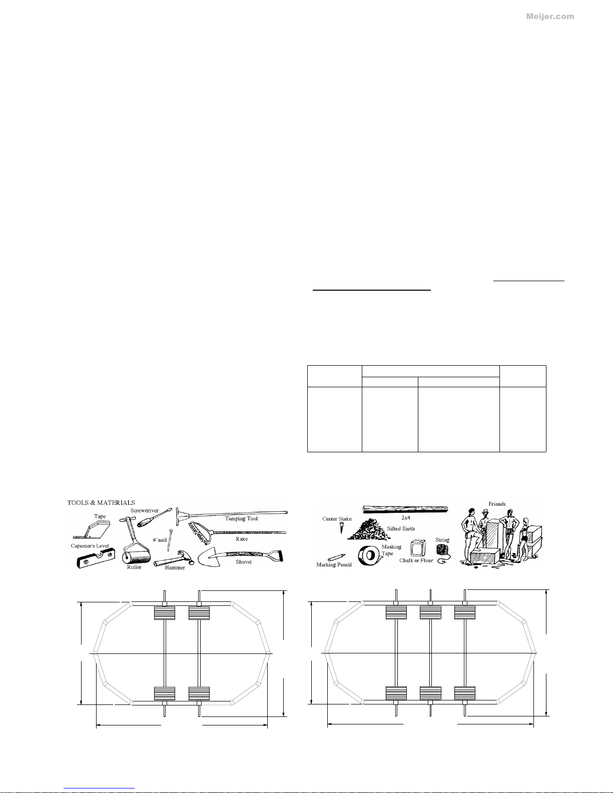
The following tools and materials are needed.
Shovel
Marking
Pencil
Masking
Tape
Rake
Chalk or
Flour
Plastic Tape
Earth Roller
String
Hammer &
Nails
Sand
2"x4" Board
Screwdriver
Tamping Tool
Pegs and
Stakes
Carpenter's
Level
Measuring Tape
Patio Block
Open the cartons and remove all part s except steel wall and liner.
Before pool assembly, you must identify, count and check all parts f or
assembly bypartslist. Familiarizeyourself wit h all of the part s. Refer
to the parts list.
a) The site must be large enough to acc ommodate the pool with
plenty of area around i t for pool accessaries, chairs, tables etc.
b) Determinewhere your filtrationand skimmer will be located.
It must be connected to a grounded110 volt electrical outlet,
with a G.F.I. (Ground Fault Interrupte r )
c) The pool must be in reac h of your water supply. Although th e
water should not be drained, but kept c lean through fi ltration and
chemicals, there shouldbe drainage facilities near in case of need.
d) Perimeter area of ground must be absolutely level and firm. All
grass and sod under entir e pool area must be dug out to avoid
unpleasant odors from decomposition under the pool due to lack of
air. Remove sharp objects, stones, twigs, pebbles, roots, etc.
They may damage the liner. If the ground has been treat e d with
chemicals or weed kil ler allow two weeks before setting up the pool.
Do not set up t he pool on concret e, a sphal t , tar paper, peatmoss,
sand, gravel, or where nut grass has been planted.
Poorly prepared ground could allow certain weeds or grass to grow
through the liner. Liner is not warranted against this. If ground is
uneven in perimeter area, dig out the high spots. Do not build up the
low side by padding it with earth. The weight and movement of the
waterwill pack downthe f i l l causing the pool to sink. Inside
perimet er o f pool (the area inside of the frame and wall) can be
leveled with 1" or 2" of sand raked and rolled smooth.
1) SELECTION OF POOL SITE
Before starti ng the installati on, the foll owing points are
important;
FAILURE TO OBSERVE ANY OF T HE ABOVE INSTRUCTIONS
WILL VOID WARRANTY.
GENERAL I NFORM ATION
Before att empting to set up the pool, read the entir e
instructions. There are certain areas in the instructions that are
extrem ely important to follow exact ly as written and/or pic t ured.
Any devi ation from these inst r uc t ions voids warranty of the pool
and could cause bodily harm or dam age to your property.
(6130mm)
(6130mm)
25x15
30x15
25'
1-3/8"
20'
1-3/8"
20'
1-3/8"
(7656mm)
(9198mm)
(4572mm)
15'
15'
(4572mm)
30'
2-1/8"
SIFTED EARTH OR SAND NEEDED
PER EACH SIZE POOL AS FOLLOWS:
CAUTION:
16' x 12' 26 cubic feet 0.79cubicM
20' x 12' 34 cubic feet 0.96cubicM
24' x 12' 42 cubic feet 1.19cubicM
25' x 15' 54 cubic feet 1.53cubicM
30' x 15' 66 cubic feet 1.87cubicM
33' x 18' 87 cubic feet 2.46cubicM
41' x 21' 127 cubic feet 3.59cubicM
POOL SIZ E Wall Length Top Sheet
mm ft in
.
Q'ty
1612 13,855 45 5 4/8 12
2012 16,364 53 8 2/8 14
2412 18, 873 61 11 16
2515 20,625 67 8 14
3015 23, 756 77 11 2/8 16
3318 26,586 87 2 6/8 18
4121 32,549 106 9 4/8 22
1
Meijer.com
(6781mm)
a) Mark off your pool area
by driving stakes. Have a
helper hold a tape measure
or a string and mark off the
pool perimeter using flour
or chalk. Rem ove sod inside
thepoolareatoadistance
of 1 feet bey ond di mensions
shown in the plot layout
around entire perimeter
of pool.
The preparation of the
ground is the most
important step in the
installat ion of the pool.
b) Remove all grass from
within the entire pool area.
It is not enoughto j ust cut
the grass. The sod must
be removed.
c) Two or three inches of sand is the best f or your liner. Using sand eli minates the necessity to level inside of frame area exc ept
where exceptionally high or low areas exist.
These areas should eitherbe dug or filled in. This does not m ean the perimeter or frame area.That area must be firm and level by
digging onl y .
d) Do not fil l low spots in the area where pool wall will rest. as setting may cause your pool to become out of level .
Making sure pool bottom is flat.This is a must.
e) If your site is not on firm soil, use 2" patio blocks for the base of the wall Care should be taken to center a patio
block under each bottom plate. The top of the patio blocks should be flush with the prepared ground surface.
2) GROUND PREPARA TION
(5216mm)
(5216mm)
(5216mm)
(8022mm)
24x12
33x18
41x21
20x12
17'
1-3/8"
26'
3-7/8"
17'
1-3/8"
17'
1-3/8"
(6401mm)
21'
33'
2-1/8"
(7319mm)
24'
1/8"
(12570mm)
19'
11-4/8"
41'
2-7/8"
(4847mm)
(6083mm)
15'
10-7/8"
(10112mm)
22'
3"
(5487mm)
(3611mm)
(3611mm)
11'
10-1/8"
11'
10-1/8"
(3611mm)
11'
10-1/8"
18'
16x12
2
Meijer.com
3
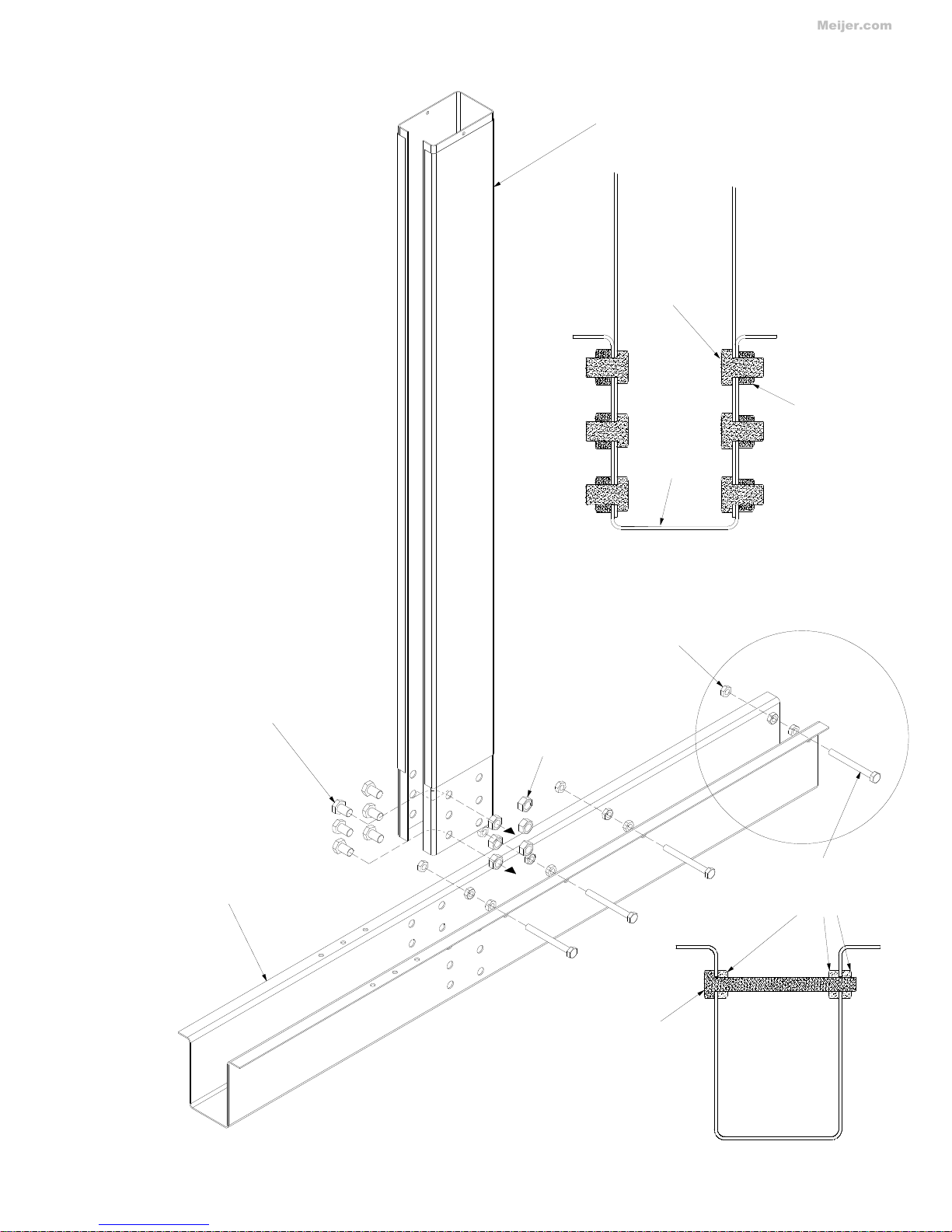
3) ASSEMBLING BRACELESS OVAL STRUCTUAL COMPONENT.
Use #0109P A CK Braceless O val frame bolt package.
Use #0105(#0106)PACK Strap bolt pac kage.
NOTE; Side vertical skin was attached to si de
vert ical at the factory,open end is
inside pool.
P.No.5712 Side Vertical for 52in
P.No.5713 Side Vertical for 54in
P.No.5617 Side Vertical Skin for 52,54i n
P.No.5726
Horizontal Support
P.No.5673
M14x30 Hex Head Bolt
P.No.5672
M14 Nut
P.No.5675
M10 Nut
P.No.5674
M10x100 Hex Head Bolt
STEP1.
Insert Side Vertical into Horizontal Support.
Insert M14 x 30 Hex Head Bolt from inside of
side vertica l,
put M14 Nut from outside
do the same six Bolt on right and left side of
side vertica l.
STEP2.
Insert M10x100 Hex Head Bolt and put three
M10 Nuts for each bolt. Do the same for three
Bolts.
as shown picture.
STEP3.
Make sure all Parts attached corrctly.
Tighten up all bolt.
Pull Side V e rtical toward outsid e of Pool.
P.No.5675
M10 Nut
P.No.5674
M10x100 Hex Head Bolt
P.No.5673
M14x30 Hex Head Bolt
P.No.5726
Horizontal Support
P.No.5672
M14 Nut
Meijer.com

4
P.No.5673
M14x30 Hex Head Bolt
P.No.5672
M14 Nut
P.No.5674
M10x100 Hex Head Bolt
P.No.5675
M10 Nut
STEP4.
Refer page-7 "5)Connecting tension staraps."
to determine kind of straps.
Attach End strap to Horizontal support. Put M8x20
hex head bolt from top and put
M8 Nut from b ottom. Put all bolt and t ighten up.
STEP5.
AttachSide Lower Rail Joint to Holizontal support
using two sets of #12 Sheet Metal Screw.
STEP6.
Attach Side Upper Jo int to top of side vert ical
using two #12 Sheet Metal S c r ew.
#12 Sheet Metal Screw
P.No.0341
3/4
P.No.0341
#12 Sheet Metal Screw
P.No.0623
M8 Nut
P.No.3177
Resin Side Upper Joint
P.No.0341
#12 Sheet Metal Sc rew
P.No.7528
End strap
P.No.0923
M8x20 Hex Head Bolt
P.No 3233
5/8" Sid e Lower Rail Joint - For 1" & 6 Frame
P.No.3222
1" Side Lower Rail Joint - For All other Frame
Meijer.com

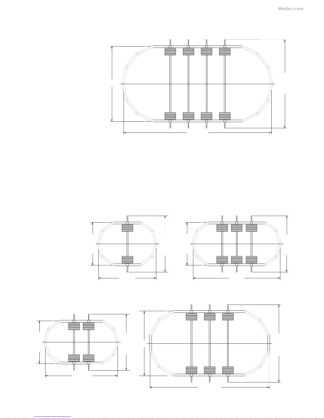
4) DRAWING POOL SHAPE
Please Draw a line with seeing the picture of eac h pool size.
(618mm)
2' 3/8"
(
1806mm)
5'
1
1-1/8"
5' 7-5/8"
(4847mm)
16x12
5'
11-1/8"
2' 3/8"
(3611mm)
(618mm)
11' 10-1/8"
(1236mm)
(1717mm)
15' 10-7/8"
(1806mm)
4' 5/8"
(7319mm)
24' 1/8"
(618mm)
2' 3/8"
4' 5/8"
(1236mm)
4' 5/8"
(
4
2
3
2
m
m
)
1
3
'
1
0
-
5
/
8
"
(1236mm)
12' 2"
(3708mm)
(
1806mm)
5' 7-5/8"
5'
1
1-1/8"
(3611mm)
11' 10-1/8"
5'
11-1/8"
(618mm)
2' 3/8"
(1806mm)
(1717mm)
24x12
7'
6
"
(765mm)
2' 6-1/8"
(1530mm)
(1530mm)
5' 1/4"
5' 1/4"5' 1/4"
7' 1-5/8"
30' 1"
(9170mm)
(2174mm)
(
2286mm)
15' 2-1/8"
(765mm)
2' 6-1/8"
7'
6"
(4572mm)
15'
(2286mm)
(
5
3
1
7
m
m
)
(4626mm)
30x15
1
7
'
5
-
3
/
8
"
5
33' 3/4"
8' 8-3/8"
(2650mm)
(10076mm)
33' 3/4"
(765mm)
2' 6-1/8"
(1530mm)
5' 1/4"
(1530mm)
5' 1/4"
(4626mm)
15' 2-2/8"
(
2744mm)
9'
(765mm)
2' 6-1/8"
(5487mm)
(2744mm)
18'
9'
33x18
20'
7
/
8
"
(
6
1
1
9
m
m
)
(
4
6
3
1
m
m
)
2' 6-1/8"
(765mm)
7'
6
"
(
2286mm)
2' 6-1/8"
(765mm)
(1530mm)
5' 1/4"
(3084mm)
10' 1-3/8"
(4572mm)
7' 1-5/8"
(2174mm)
15'
25x15
7'
6"
(2286mm)
15'
2
-
3
/
8
"
(7638mm)
25' 3/4"
X Point
Wall
(618mm)
(
1806mm)
5'
1
1-1/8"
11'
1
1
-
3
/
4
"
(
3650m
m
)
2' 3/8"
11' 10-1/8"
5'
11-1/8"
20x12
2' 3/8"
(618mm)
(1717mm)
(1806mm)
8' 1-3/8"
(2472mm)
4' 5/8"
5' 7-5/8"
(1236mm)
Side Vertical
19' 11-4/8"
(6083mm)
(3611mm)
Meijer.com

Note:
All Bolts to be inserted from the top side, Nuts to be
inserted from undernerath Tension straps.
End starp ; 7528 This should be used for the end.
Middle strap ; 7254, 7244, 7264 or 7285. Those should be
used for the middle.
Connect Middle strap(s) to already assembled End straps.
Using five sets of M8x20 h ex h ead bol t and M8 nut .
Use #0106.PACK Strap Bolt Package
Use #0105.PACK Strap Bolt Package
5) CONNECTING TENSIO NSTRAPS
6
P.No.0623
P.No.0623
M8 Nut
M8 Nut
P.No.0923
P.No.0923
M8 x 20 Hex Head Bolt
M8 x 20 Hex Head Bolt
7528 - 2pieces 33x18 - 3straps.
7264 - 2pieces
7528 - 2pieces 41x21 - 4straps.
7285 - 3pieces
7528 - 2pieces 25x15 - 2straps.
7244 - 2pieces 30x15 - 3straps.
7528 - 2pieces 16x12 - 1straps.
7254 - 1pieces 20x12 - 2straps.
24x12 - 3straps.
Quantity per set. Number of sets per pool .
12' Width Oval Pools
18' Width Oval Pools
15' Width Oval Pools
21' Width Oval Pools
Combination of Strap Set
20mm
(6120mm)
41' 1"
10'
6
"
(12520mm)
(3120mm)
5' 1/4"
(
3200mm)
2' 6-1/8"
(1530mm)(1530mm)
10' 2-7/8"
5' 1/4"
20' 1"
(765mm)
10'
6"
21'
2
5
'
5
"
(
7
7
4
7
m
m
)
(1530mm)
(6401mm)
2' 6-1/8"
41x21
(765mm)
5' 1/4"
(3200mm)
Middle strap
End strap
This end should be connected
to horizontal support.
7528 End 55-1/8" 1400
7254 Middle 32-7/8" 835
7244 Middle 36-5/8" 929
7264 Middle 55-3/8" 1405
7285 Middle 50-5/8" 1286
Parts No. Type Length(in) Length
(mm)
Length of Tension Straps.
Meijer.com

Set all oval parts on the right position, Chec k (A)
length(distance between horizontal
support), Put Top seat on top of side upper joint
temporaly as shown figure.
Then check a-b,c- d is straight and lebel ,If not,
adjust accordingly.
Do not use wood to adjust height.
7
6) POSITIONING ASSEM BLED OVAL PARTS
.
Digging holes for assem bled braceless oval structural
components. Use Building block to hold assembled braceless
oval st r uc tural component . Stamp ground under bui lding block
well to bellow than needed level. Put some sand t o the ground
and pour some water to make sand tight. Then put building
block on top of sand. Adj ust building block ac c ordingly.
Top seat temporally placed should be removed before
proceeding to next step.
Cinder Block
Cinder Block
(753mm)
(1369mm)
(138mm)
5-3/8" Depth
29-5/8"
53-7/8"
X Point
Sand
IMPORTANT !
Cinder Block
Cinder Block
A
b
d
c
a
Pool Size (A)Length
(in)
(A)Length
(mm)
16x12 4' 5/8" 1236
20x12 4' 5/8" 1236
24x12 4' 5/8" 1236
25x15 5' 1/4" 1530
30x15 5' 1/4" 1530
33x18 5' 1/4" 1530
41x21 5' 1/4" 1530
List of (A) Length
Meijer.com
Bringthewallclosetothebottomrail.
Make sure there is nothing in the bottom rail before inserting the wall. If there is
earth or something is in the bottom rail,take out it accordingly.
Begin to insert end of wall into bottom rail. One person unwinding wall (wall
should be on a plywood base for ease of rotating) while the other person is
feeding wall into slot of bottom rail around entire pool.
As you unwind the wall and insert it into the assembled bottom rails, temporarily
placetop rail sections on top of the wall. This will help to prevent the wall form
bending or falling over.
Should the wall be either too short or too long,Adjust bottom rails,The
circumference of bottom rails can be adjusted slightly by equally tapping
outward or inward at the each lower joint until the wall ends meet.
Bring the two open ends of the wall together as shown above.
This is oneof the most importantsteps in assembling the pool. Pay close
attention to the following points.
There is an up and down side on steel wall. Locate the skimmer cutouts
which are near the outside end of the wall . These cutouts must be at the
TOP even if you will not be using these cutouts .
Place coiled wall near bottom rail one section open.
8) INSTALLING WALL
It is practic al if two people work together; one inside and one outside of the
pool.
Due to the weight of wall,some bending will occur in the top and bottom corrugation.
because the wall is built to flex. Simply bend those sections back before inserting wall in
top or bottom rail.
Use Wal l Joint Bolt Package packed in a Wall Carton.
Bottom rails between the hor izontal supports are set up by inserting each end of bot t om rail into side lower joint, I nsert the bottom rails around the entire
perimeter using lower joints on the circular portion of the pool.Leave one section open that will be nearest to where you will locateyour filter.
Before proceeding to the next step, place a large amount to sifted earth in the mi ddle of the circle. (see chart for the amount on the first page.)
Sifted earth should not contain any pebbles.
Place a patio block under each lower joint around curved area.Make sure top of patio block is flush with ground surface and t op of hori z ontal support.
Before proceeding, remove the steel wall from carton and stand on a 3'x3' board inside pool area as shown at down. Put the liner, (leaving it in the
carton) inside pool area.
7) ASSEMBLING BOTTOM RAIL
Step 4:
STEP 1:
STEP 3:
Note:
STEP 2:
STEP
1:
STEP
2:
8
Put Pressure plate by Using #12 Sheet
Metal Screw after Positioning Assembled
oval parts.
Pressure Plate
P.No.6254
P.N.-0513
1/4 x 1/2in Truss Head Sc r ew
1/2
P.N.-0611
1/4in Nut
WALL
WALL
NUT
INSIDE OF POOL
BOLT
REINFORCING
WASHER
P.N.-0411
1/4in Reinforcing Washer
φ 1 3/8
#12 Sheet Metal Screw
P.No.0341
3/4
Meijer.com

DO NOT FASTEN THE WALL WITHOUT USING THE REINFORCING
WASHERS ! FAILURE TO USE REINFORCING WASHERS AS
INSTRUCTED WILL CAUSE WALL TO SPLIT WHEN POO L IS FILLED.
THIS CAN CAUSE SERIOUS PROPERTY DAMAGE AND/OR BODILY
INJURY.
INSERT THE SCREWS FROM INSIDE OF WALL.
NUT MUST BE FASTENED FROM OUTSIDE OF
WALL.
* Reinforci ng Washers must be on INSID E and OUTSIDE of wall.
* Insert the screws from INSIDE of the wall.
* Insert and fasten screws from hole to hole down to the bottom
of the wall.Do not fasten tightly before insert all screws.
* Fasten all screwstightly.
* Do not leave any open holes.
* Cover all the screw heads with strip of fabric tape.
* Check the level of the top of the wall,if more than 2" off level ,
Rework the ground to achieve levelness.
Unfold the lineri nside the metal wall. Carefully spread it out on
the ground. The seam around the bottom of the liner should be
well up the earth mound. Do this evenly all around pool.
Remove your shoes. The liner should never be forcefully pulled
or dragged, especially when it holds water, even only 1/2".
When you enter the pool during installation, use a ladder other
than a pool ladder.
Make sure the legs rest on a strong flat board
Open the liner carton carefully by removing the tape. (Do not
cut open carton.)
For untirusting, All edges of cut out have to be covered by vinyl
tape or rusting paint.
Begin the installation of the through the wall skimmer. Follow
separate skimmer installations.
At one point during the installation of the skimmer, you have to
installthe liner. The skimmer installationwill tell you when.
Complete the installation of the liner as described next. Then
finish the skimmer installation.
Build a mound 6" high and extending 8 to 10" on the ground
around the inside of the pool wall. Pack the earth gently but
firmly.
9) BUILD AN EARTH MOUND(cove)
The earth mound must be built right. you must rebuild the earth mound each
time you set up the pool. Water pressure can force the liner out under the
bottom rail. If this is not done.This could cause damage to the liner and void
warranty. The earth mound will prevent this from happening.
11) LINER INSTALLA TI O N
10) THROUGH THE WALL SKIMMER
Remove top rail temporarily placed.
Lift the side of the liner over the top o f the wall. Form a col lar
approximately 3" down the outside of the wall and temporarily
tape it, to the outside of the wall using masking tape at intervals
of 3'.
Take t he plastic edging and clip it over the li ner and the top of
the wall. The ends of each section of edging should touch
each other. The edging forms a full circle all around. Cut
off excess plasticedging
If the liner does not fit evenly around the pool.
Remove the masking tape gently from the collar of the liner and wall.
Smooth out all wrinkles on the bottom of the liner. There may be
extra material a round the side. Spread it evenly all around the side of
the pool. There may be extra material in height.
IMPORTAN
T:
Step 2:
Step 1:
CAUTION:
Step 1:
Step 3:
Step 4:
4)
To keep the water clean and protect your liner from being damaged it is
best to cover hose end(s) with several layers of rags.
3)
Set as many hoses as you want to help speed up filling time. The pool
holds a considerable amount of water (ie;18' round pool holds 7650
gallons.).
2)
Measure all around the pool, from the TOP RAIL down to WATER
LEVEL. This level SHO ULD NOT VARY MORE THEN ONE INCH.
An unleveled condition will cause overstress of the pool wall and frame.
Remove excess soil as required to establish a level frame and bottom
rail condition.
See " ASSEMBLY OF BOTTOM RAILS "
1)
INSPECT BOTTOM RAILS-make sure they are not scalloped, see
detail at right. If rails scallop, pull outward at the bottom of the
verticals to allow wall and rails to assume natural shape.
By using a string and smal l weight, check each vertical.To see that they
stand straight.
Be sure each vertical stands perfectly straight.
IMPORTANT: STOP FILLING POOL AT 1 FOOT DEPTH
When pool is completely assembled and ready for water, run water into
the pool. Wrinkles in pool liner should be smoothed out as water is
added for easier maintenance.
The hard work is all behind.
Now the fun begins.
12) FILLING THE POOL
CAUTION:
Do not attempt to straighten li ner after you begin to fill with water.
Severe damage could be caused and You will void warranty.
5)
When desired water level is reached, turn on your fi lter.
(Follow separate instructions provided with your filter.)
2in
6in
9
1/4in Reinforcing Washer
1/4in Reinforcing Washer
1/4in Reinforcing Washer
1/4in Reinforcing Washer
INSIDEOF POOL
INSIDEOF POOL
Please refer to "Assemble TopSeat ,
Vertical and Cover" of an attached sheet
Meijer.com

10
Leaks in skimmer and filter connections must be stopped.
A constant drip of chl or inated water on metal will corrode t he metal.
a)
Proper filtering and chemical treatments should not make it necessary
to change the pool water.
Your pool dealer will advise you of the proper procedure.
To estimate the amount of chemicals needed here is the approximate
water content of the pool based on full capacity:
To help keep the pool clean and child proof, a pool cover should be on
the pool whenever it is not in use. This also reduces loss of water and
chemicals.
To keep the pool in working condition check the following operation.
2.
1.
13) HELPFUL INFORMATION
1.
14) SAFETY RULES
Read your instructions and safety rules carefully. If you do not follow
the safety rules someone could be injured or damage could occur.
2. Plan carefully where you are going to put your pool. It must be close to
a watersourcefor f illing. Also think about draining your pool.
3. Never let anyone swim alone. Children must be carefully watched. For
added safety, install a convex type mirror above pool to give full view
of interior.
Available at most mirror dealers.
4. Do not let anyone rough-house in or around your pool . The pool area
and decks can be slippery. Someone could be badly injured. You can
prevent this type problem by enforcing the safety rules.
5. Always keep the water clean and sanitary. Dirty water can be
dangerous. Use your filter system. Follow instructions included with
your filter. Also use water purifying chemicals as needed.
6.
DO NOT DIVE OR JUMPINTO YOUR POOL. THE POOL IS NOT
DESIGNED FOR DIVING OR JUMPING !
7.
Remove ladders when there is no adult to watch the pool.
Remove anything else that can be used get into the pool.
Use a cover if the pool is not in use for a long period of time.
SAFETY DECALS CAN BE AFFIXED TO A CLEAN,DRY,
SMOOTH SURFA CESUCH AS THE V INYL LINER,TOP
SEAT THAT HAS SMOOTH FINISH. THEY MUST BE
PLACED THAT THEY ARE EASILY SEEN.
Do not emptyyour pool in spring. Filtration andchlorinationwill
remove all impurities. Leaves and other matter should be skimmed or
vacuumed out of the pool.
The pool should be left up and filled year round properly winterized and
covered with a good cov er . The water level must be lowered t o about
6" below the lowest skimmer opening if your area is subjected to be
below freezing temperature. All pool leaks must be repaired before
winter.
c)
b)
Jumpin g and diving into a ASAHICHEMICAL's Pool i s
STRICTLY FORBIDDEN
.
It is your responsibility as the owner of the pool to do the following:
Do not locate pool near objects that would entice diving i.e. garages, t r ee, porches, etc.
Do not let anyone use your pool unless they are fully aware of the DO NO T DIVE OR JUMP notice.
Do not promote horse play or other act ivities that would cause injuries.
Do not allow people to sit or walk on the t op seat of the pool.
IT IS YOUR RESPONSIBILITY AS A POO L OWNER TO INSURE T HE SAFETY OF WHOMEVER USES THE POOL
NOT THE MANUFACTURER.
READ ALL INSTRUCTIONS CAREFULLY BEFORE ASSEMBLING YOUR POOL.
Readthrough all instructions completely and familiarize yourself with all pool parts and accessoriesbefore pool assembly.
Damage may be done if a ll instructions are not carefully followed, and in such cases, will void manufacturer's warranty.
When assembling pool, read through what you must do for each step, then proceed.
WA RNING
THIS POOL IS DESIGNE DFOR SWIMM ING ONLY. IT IS NOT INTENDED FOR DIVING O R JUMPING.
FOR A MAXIMUMOF SWIMMING FUN, BE SURE TO FOLLOW A LLSAFETY RULES WHEN USING ANY SW IMMI NG P OO L.
Printed in JAPAN. Oct. 2009.
Pool Size Capacity
gallons
Pool Size Capacity
gallons
16x12x52 5,050
20x12x52 6,585
24x12x52 8,117
25x15x52 10,481
30x15x52 12,902
33x18x52 16,836
41x21x52 24,614
16x12x48 4,661
20x12x48 6,079
24x12x48 7,493
25x15x48 9,675
30x15x48 11,910
33x18x48 15,541
41x21x48 22,721
PERMANET INJURY OR DEATH CAN RESULT.
DANGER
DO NOT
DO NOT
JUMP
DIV E
Meijer.com

11
Meijer.com
 Loading...