

Mighty Pure MP16A, MP22A, MP49C, MP36C Owner's Manual

Models MP16A, MP22A, MP36C & MP49C
Read and Follow All Safety Instructions. Save These Instructions.
Owner
Owner
’
’
s Manual
s Manual
Extensive Product Information Available at:
ultraviolet.com
buyultraviolet.com
Document No. 98-1376D • August 2016 • ©2016 Atlantic Ultraviolet Corporation® • MADE IN THE USA
Installation,
Operation
& Maintenance
1

TABLE OF CONTENTS
SAFETY WARNINGS .......................................................................................................................................................................3
SAFETY INSTRUCTIONS ..............................................................................................................................................................3
SAFETY LABELING ........................................................................................................................................................................3
CAUTION ...........................................................................................................................................................................................3
PRODUCT APPLICATION .............................................................................................................................................................4
ConstruCtion .................................................................................................................................................................................................... 4
PrinCiPle of oPeration .................................................................................................................................................................................... 4
limitation of use .............................................................................................................................................................................................. 4
Water Quality ................................................................................................................................................................................................. 4
INSTALLATION ...............................................................................................................................................................................5
loCation .........................................................................................................................................................................................5
Dimensional Data...........................................................................................................................................................................5
reCommenDeD installation ............................................................................................................................................................6
initial installation of Quartz sleeve moDel mP49C ............................................................................................................. 7-8
reCommenDeD oPtions....................................................................................................................................................................9
MAINTENANCE .............................................................................................................................................................................10
insPeCtion .....................................................................................................................................................................................10
DisPosal of merCury aDDeD lamP ..............................................................................................................................................10
lamP installation or rePlaCement .............................................................................................................................................11
Quartz sleeve installation Cleaning or rePlaCement .............................................................................................................12
rePlaCement of Broken Quartz sleeve ......................................................................................................................................13
Cleaning of oPtional guarDian
tm
ultraviolet monitor sensor ProBe ....................................................................................14
TROUBLESHOOTING ..................................................................................................................................................................15
TECHNICAL SPECIFICATIONS .................................................................................................................................................16
OPTIONAL ACCESSORIES .........................................................................................................................................................17
REPLACEMENT PARTS ......................................................................................................................................................... 18-21
Mighty«Pure® moDels MP16A & MP22A .......................................................................................................................... 18-19
Mighty«Pure® moDels MP36C & MP49C .......................................................................................................................... 20-21
MAINTENANCE NOTES ........................................................................................................................................................ 22-23
USER ASSISTANCE .......................................................................................................................................................................24
WARRANTY ....................................................................................................................................................................................24
Patent notiCe ...............................................................................................................................................................................24
These instructions generally describe the installation, operation and maintenance of the Mighty«Pure
®
line of water puriers,
Models MP16A, MP22A, MP36C and MP49C. Questions that are not specically answerable by these instructions should be
directed to the Factory.
Atlantic Ultraviolet Corporation takes all possible precautions when packaging equipment to prevent damage. Carefully inspect
and report all damages. Do not install damaged equipment.
Follow all instructions on any labels or tags. Carefully inspect all packing materials before discarding to prevent the loss of
accessories, mounting hardware, spare parts or instructions.
The information and recommendations contained in this publication are based upon data
collected by the Atlantic Ultraviolet Corporation® and are believed to be correct. However, no
guarantee or warranty of any kind, expressed or implied, is made with respect to the information
contained herein. Specications and information are subject to change without notice.
2
SAFETY WARNINGS
!
• All personnel should be alerted to the potential hazards indicated by the product safety labeling on this unit.
• The following conventions are used to indicate and classify precautions in this manual and on product safety labeling. Failure to
observe precautions could result in injury to people or damage to property.
This is the safety alert symbol. It is used to alert you to potential personal injury hazards.
Obey all safety messages that follow this symbol to avoid possible injury or death.
Danger indicates an IMMINENTLY
hazardous situation, which, if not avoided,
WILL result in death or serious injury.
Caution indicates a POTENTIALLY
hazardous situation, which, if not avoided,
MAY result in minor or moderate injury.
This symbol/pictorial is used to identify an ELECTRI-
CAL SHOCK or ELECTROCUTION hazard.
This symbol/pictorial is used to identify the need to
wear approved ultraviolet blocking eyewear.
This symbol/pictorial is used to identify the need to
wear protective gloves.
This symbol/pictorial is used to identify an
ULTRAVIOLET LIGHT hazard.
This symbol/pictorial is used to identify the need to
wear approved ultraviolet blocking face shield.
This symbol/pictorial is used to identify components
which must not be disposed of in trash
Warning indicates a POTENTIALLY
hazardous situation, which, if not avoided,
COULD result in death or serious injury.
Caution used without the safety alert symbol indicates a potentially hazardous situation, which,
if not avoided, may result in property damage.
SAFETY INSTRUCTIONS
To guard against injury, basic safety precautions should be observed, including the following:
1. Read and follow ALL safety instructions.
2. Do not use this water purier for other than its intended purpose as described in this manual.
3. Do not alter design or construction.
4. Do not remove any labels or devices.
5. To prevent the risk of severe or fatal electrical shock, special precautions must be taken since
water is present near electrical equipment. Always disconnect power before performing any service or maintenance.
6. Avoid exposure to direct or reected germicidal ultraviolet rays. Germicidal ultraviolet rays are
harmful to the eyes and skin.
7. Intended for indoor use only. The water purier should be protected from the elements and from temperatures below freezing.
8. Do not operate water purier if lamp cable, lamp connection, power cord and/or plug are damaged, or if any other damage to
the water purier is visible or suspected
9. Electrical power supplied, to the water purier, MUST match power requirements listed on the water purier.
10.
Plug the water purier only into an approved ground fault circuit interrupt (GFCI) receptacle.
11. Do not operate without proper electrical ground.
12. Do not exceed water purier’s maximum rated ow capacity.
13. Do not exceed maximum operating pressure of 100 PSI.
14. Read and follow all notices and warnings on the water purier.
15. SAVE THESE INSTRUCTIONS.
SAFETY LABELS CAUTION
It is the user’s responsibility to determine and validate the
suitability of this equipment for use in the user’s system or
process.
No warranty or representation is made by the manufacturer
with respect to suitability or performance of this equipment
or to the results that may be expected from its use.
The user should periodically inspect, clean as necessary
and conrm the presence and good legibility of the product
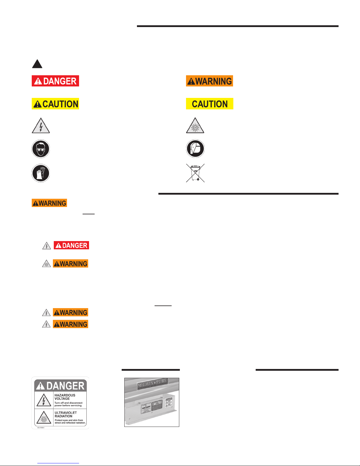
Danger Label: Hazardous Voltage
and Ultraviolet Radiation (00-0196A1)
Location of Danger Label
(00-0196A1)
safety labels. Contact the factory for replacement labels in
the event that any of the labels are missing or illegible.
3

PRODUCT APPLICATION
ConstruCtion
• The water purier is designed to mount horizontally.
• A drain port on the chamber aids in draining of the purier.
• The water purier’s chamber and chamber head are passivated and electropolished type 316 Stainless Steel.
• The ballast housing is a combination of Stainless Steel Type 304 and Aluminum Alloy.
• EASY-OFFTM end caps enable quick and easy lamp change, without disconnecting from the water supply or draining the
purier. No tools are required.
PrinCiPle of oPeration
The Mighty«Pure® design has been carefully conceived to provide adequate germicidal dosage throughout the disinfection
chamber. The dosage, as it applies to ultraviolet disinfection, is a function of time and the intensity of ultraviolet radiation to
which the water is exposed. The exposure time, in seconds, is the total time it takes the water to ow through the disinfection
chamber exposing it to the germicidal lamp. Exposure time is related to the ow rate; the higher the ow rate, the lower the
exposure time or the lower the ow rate, the higher the exposure time. The ultraviolet intensity is the amount of energy, per unit
time, emitted by the germicidal lamp. The dosage is the product of ultraviolet intensity and the exposure time. The operation of
the Mighty«Pure® is as follows:
• Water enters the purier and ows into the annular space between the quartz sleeve and the chamber wall.
• Suspended microorganisms are exposed to the ultraviolet rays emitted by the germicidal lamp.
• The translucent sight port, or optional ultraviolet monitor, provides visual indication of germicidal lamp operation.
• Water leaving the purier is instantly ready for use, no further contact time is required.
limitation of use
The water purier is intended for the use with visually clear water, not colored, cloudy or turbid. See “Water Quality” section
below. The water purier is NOT intended for the treatment of water that has an obvious contamination or intentional source,
such as raw sewage; nor is the unit intended to convert wastewater to microbiologically safe drinking water.
Water Quality
Water quality plays a major role in the transmission of germicidal ultraviolet rays. It is recommended that the water does not
exceed the following maximum concentration levels:
Table 1 - Maximum Concentration Levels
Turbidity < 1 NTU
Manganese 0.05 mg/1
Total Suspended Solids 10 mg /1
pH: 6.5 - 9.5
Color: None
Hardness 6 GPG or 102.6 PPM
Iron 0.3 mg/1
Tannins: < 0.1 ppm (0.1 mg/l)
UV Transmission >85% per cm*
* Contact Factory for recommendations on applications where UV transmission is < 85%
Effectively treating water with higher concentration levels than listed above can be accomplished, but may require added
measures to improve water quality to treatable levels. If, for any reason, it is believed the ultraviolet transmission is not
satisfactory, contact the factory.
4
INSTALLATION
loCation
1. The water purier is intended for indoor use only. The water purier is designed to mount horizontally. The water purier
should be protected from the elements and from temperatures below freezing. The ambient temperature, in the area
surrounding the water purier, should be between 35o F and 100o F.
2. Electrical power supplied to the water purier MUST match power requirements listed on the water purier. Use of a voltage
surge protector is recommended.
3.
4. The water purier should be located in a dry, well-lit area, which provides enough room to perform routine maintenance. This
includes a minimum distance of one chamber length from the chamber end, to allow for cleaning and/or the changing of the
lamp and quartz sleeve as well as a minimum of 6” on the opposite end of the water purier. Minimum clearance to oor 18’’.
5. The water purier should always be located closest to the point of use. This reduces the chance of the puried water being
re-contaminated by bacteria in the water distribution system after the water purier.
6.
condensation or leakage from the water purier, any purier accessory and/or plumbing will not result in damage to the area
surrounding the water purier. For added protection, it is recommended that a suitable drain pan be installed under the
purier. The drain pan must be plumbed to an adequate, free owing drain to prevent water damage in event of a
leak. There are numerous leak detection/ood stop devices, available on the market today, designed to stop ow of
water, reducing the chance of water damage due to leakage. For more details regarding leak prevention and/or
limiting damages due to leaks please contact factory.
7. The water purier should be located after all other water devices, such as De-ionizers, Water Softeners, Carbon Filters,
Pre-Filters, Reverse Osmosis, Pressure Tanks, and Pumps. This eliminates the possibility of the puried water being
re-contaminated by bacteria in any of these units.
Plug water purier only into an approved ground fault circuit interrupt (GFCI) receptacle.
As with any water handling device, the water purier should be located in an area where any possible
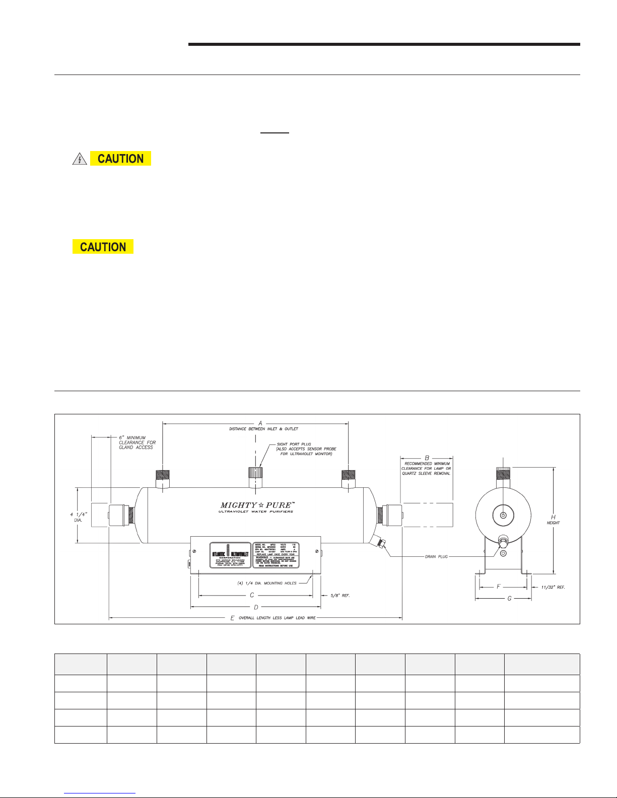
Dimensional Data
Figure 1 -Mighty«Pure® Dimensional Drawing
Model A B C D E F G H Inlet/Outlet
MP16A 8-3/4” 16” 8-3/4” 10” 16-1/2” 3-5/8” 4-5/16” 8-3/16” 3/4”m NPT
MP22A 14-3/4” 22” 13-1/4” 14-1/2” 22-1/2” 3-5/8” 4-5/16” 8-3/16” 3/4”m NPT
MP36C 28-1/2” 36” 16” 18” 36-1/2” 4-15/16” 5-11/16” 9-1/2” 1”m NPT
MP49C 40-7/8” 49” 26” 30” 49-1/2” 4-15/16” 5-11/16” 9-1/2” 1- 1/2”m NPT
All specications, dimensional data, etc are approximate and subject to change without notice.
Table 2 - Mighty«Pure® Dimensional Data
5
installation
IN ORDER TO PERFORM THIS TASK, BE SURE TO WEAR THE FOLLOWING SAFETY
EQUIPMENT: SAFETY GOGGLES OR A FACE SHIELD, AS WELL AS GLOVES
1. Remove water purier from shipping carton. Inspect water purier, power cord and plug for damage. Do not operate if
there is any damage to the purier, power cord or plug. Models MP16A through MP22A are shipped with the lamp already
installed, while the lamp in the MP36C and MP49C is packed separately. Keep the lamp aside for installation once the
purier has been properly installed.
2. Units occasionally experience damage in shipment due to the fragility of the quartz sleeve. It is, therefore, recommended to
inspect the water purier for damage to the quartz sleeve after it has been removed from the shipping carton. Each end of the
unit as well as the inlet and outlet should be viewed to see if the quartz sleeve has experienced damage. If the quartz sleeve
shows signs of damage it should be replaced before the purier is pressurized. See “Quartz Sleeve Installation, Cleaning
or Replacement” in the “Maintenance” section for the proper method of replacing the quartz sleeve in your water purier.
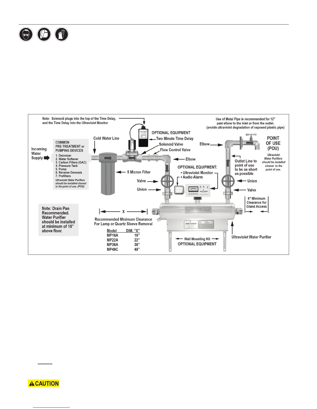
Figure 2 - Recommended Installation
3. The water purier should be mounted horizontally on a at dry surface. Secure the water purier using the mounting holes
in the ballast housing or with the optional wall mounting kit. The purier should not be solely supported by its plumbing
connections.
4. The water purier must be connected to the cold water line only. Inlet water temperature should not exceed 100°F.
5. Installation requires that a 5-micron sediment lter or ner be installed, in line, prior to the water purier. The sediment lter
will stop or trap large particulates from entering the water purier. Particulates may cause damage to the quartz sleeve, as
well as interfere with the purier’s ability to disinfect the water. The sediment lter may also help to reduce the amount of
routine cleanings of the quartz sleeve.
6. Shut off valves should be installed on both the inlet and outlet sides of the water purier. The use of bypass valves is not
recommended. The shut off valves allow the purier to be isolated from the water supply, which is required when removing
the quartz sleeve.
7. Unions should be installed on both the inlet and outlet of the water purier; this will allow easy removal of the water purier
from the plumbing, if required. Apply Teon® tape to threads of inlet and outlet ports to ensure a tight seal.
8. When all plumbing connections are complete, allow water to enter the water purier at a low ow rate, until the purier is
full. NOTE: Close the purier outlet valve to pressurize the chamber. With the purier pressurized, it should be checked
for leaks. Once it is determined that there are no leaks, the inlet valve can be fully opened.
9. For Models with lamps packed separately, install lamp following the steps in “Lamp Installation or Replacement” section.
Lamp and quartz sleeve are easily damaged. Exercise care when handling. (Continued on Page 7)
6

10. Plug water purier into approved ground fault circuit interrupt (GFCI) receptacle. Conrm lamp
operation indication at sight port.
11. Once the plumbing hook ups are made, it is a good practice to disinfect the “downstream” plumbing between the purier and
point of use. This is done by introducing chlorine or other disinfectant solution directly into the purier chamber, a 100ppm of chlorine is suggested. With the disinfectant solution in the purier chamber, turn the ultraviolet purier on. Open the
“downstream” outlet until a chlorine or disinfectant solution odor is noticed. Close the outlet and allow the disinfectant to
remain in the plumbing for at least three (3) hours. Flush the plumbing with ultraviolet puried water; allow the water to run
for a minimum of 5 minutes before use (to ensure no chlorine or disinfectant solution smell can be detected), this will allow
the chlorine or disinfectant solution to be ushed through the pipes.
For added protection, a suitable drain pan must be installed under the purier. The drain pan must be plumbed
to an adequate, free owing drain to prevent water damage in the event of a leak. There are numerous leak detection/ood stop
devices, available on the market today, designed to stop the ow of water, reducing the chance of water damage due to leakage. For
more details regarding leak prevention and/or limiting damages due to leaks, please contact the factory.
initial installation of Quartz sleeve moDel mP49C
(shiPPeD Without Quartz sleeve installeD)
IN ORDER TO PERFORM THIS TASK, BE SURE TO WEAR THE FOLLOWING SAFETY
EQUIPMENT: SAFETY GOGGLES OR A FACE SHIELD, AS WELL AS GLOVES
Water Purier should NOT be installed or plumbed prior to following the instructions on this page.
NOTE: Some Mighty«Pure® Model MP49C models are packed without a quartz sleeve installed in the water purier chamber
and instead have a PVC pipe installed temporarily (for shipping purposes). Please follow these instructions if applicable.
1. Pull off EASY-OFFTM end caps from static gland nut on each end of the water purier chamber.
2. Unscrew static gland nuts from each end of the chamber and remove Teon® washer and o-ring from both ends of PVC pipe.
Set aside.
3. Remove PVC pipe and discard (REMINDER: be sure that the Teon® washer and o-ring from both ends of PVC pipe are
removed before discarding)
4.
handling. Remove quartz sleeve from separate package inside the carton which had contained the water purier.
5. Align the end of the quartz sleeve with the gland tting on the chamber (the quartz sleeve can be inserted into the chamber
from either end of the water purier chamber).
6. Carefully slide the quartz sleeve into the chamber guiding it through the gland tting. Make certain the quartz sleeve is
aligned in the center of the chamber. Do not force the sleeve sideways. This will result with the quartz sleeve breaking.
7. As the quartz sleeve nears the far end of the chamber, guide and support the quartz sleeve by inserting your nger through
the far end gland tting and into the end of the quartz sleeve. This will minimize the possibility of accidental breakage as the
quartz sleeve passes through the gland tting.
8. Center the quartz sleeve so equal lengths are protruding at each end past the gland ttings.
9. Reassemble the o-rings (Figure 3), Teon® washers (Figure 3) and gland nuts (Figure 3) in the order shown in Figure.
TAKE CARE NOT TO DAMAGE THE QUARTZ SLEEVE WHEN INSTALLING THE GLAND NUTS. STRIKING THE
SLEEVE WITH THE GLAND NUT WILL BREAK THE END OF THE QUARTZ SLEEVE.
10. Tighten the static gland nuts rmly by hand. DO NOT USE HAND TOOLS. Using hand tools is likely to cause quartz
sleeve to break.
11. Proceed to the “Lamp Installation or Replacement” section of this manual to properly install the germicidal ultraviolet
lamp in the water purier.
Broken Quartz is SHARP. It is recommended that protective goggles and gloves are worn when
7
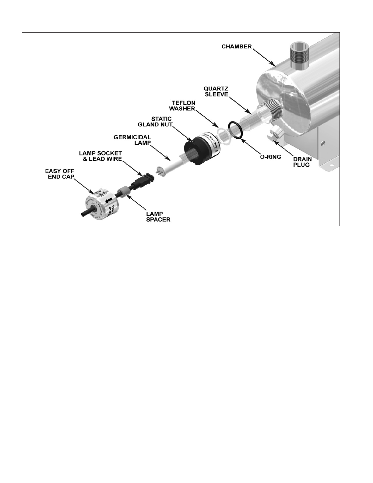
Figure 3 - Initial Installation of Quartz Sleeve
8
 Loading...