

Page 1
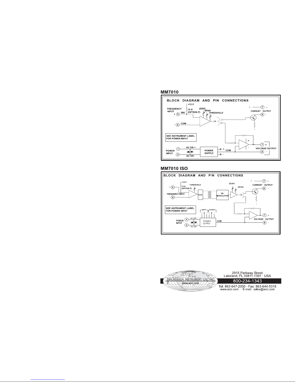
MM7010 &
MM7010 ISO
FREQUENCY INPUT
TRANSMITTERS
DESCRIPTION
The MM7010 is used to provide a DC
output voltage or current proportional to
the frequency of the input signal. It is
useful for measuring speed of motor,
conveyors, or other devices that can
create a periodic signal proportional to the
desired function. The wide range of input
sensitivity allows the MM7010 to be driven
from low level magnetic pickups as well
as logic level signals.
A threshold adjustment sets the minimum
input amplitude the module will process.
This allows the user to trade off sensitivity
versus noise rejection. An optional pullup
resistor (Option P) permits use with
contact-closure or open-collector inputs.
OPTIONS
The following options are available on
the MM7010 & MM7010ISO:
P 10 kilohm pullup resistor for use
with open-collector or contactclosure inputs.
U All circuit boards conformal coated
for protection against moisture.
DC Power
Inverter-isolated 12 V or 24 VDC
power.
CONTROLS
Three controls, ZERO, SPAN and
THRESHOLD, are accessible from the top
of the module.
CALIBRATION
The MM7010 is shipped with ZERO and
SPAN pre-calibrated. The user need only
adjust the THRESHOLD for the desired
sensitivity.
The THRESHOLD adjustment allows the
module to be made insensitive to the line
frequency pickup or other noise signals
whose levels are below the threshold
setting. Turning this control fully clockwise
reduces the threshold to zero and makes
the input most sensitive.
To adjust, set the input at about half-scale
frequency and at about 25% of its normal
amplitude. Turn the THRESHOLD control
fully clockwise then, while monitoring the
output, turn the control counterclockwise
until the output drops (suddenly) to its
low-end value. NOTE: If the output does
not drop, leave the control fully
counterclockwise.
To re-calibrate ZERO and SPAN, proceed
as follows:
Refer to the instrument's label to determine
your instrument's supply voltage and input
and output ranges. Refer to the “Block Diagram
and Pin Connections” for pin connections.
Connect a calibrated frequency source to
the input of the instrument. (Option P, if noted
on the label, indicates a pullup resistor has
been added for use with switch-closure or
open-collector input (See Block Diagram and
Pin Connections).
Set the input frequency to the low end of the
input range and adjust the ZERO control for
the low-end of the input range and adjust the
ZERO control for the low-end output voltage
or current. Increase the input frequency to
full scale and adjust the SPAN control for the
full-scale output. Repeat until both readings
are correct.
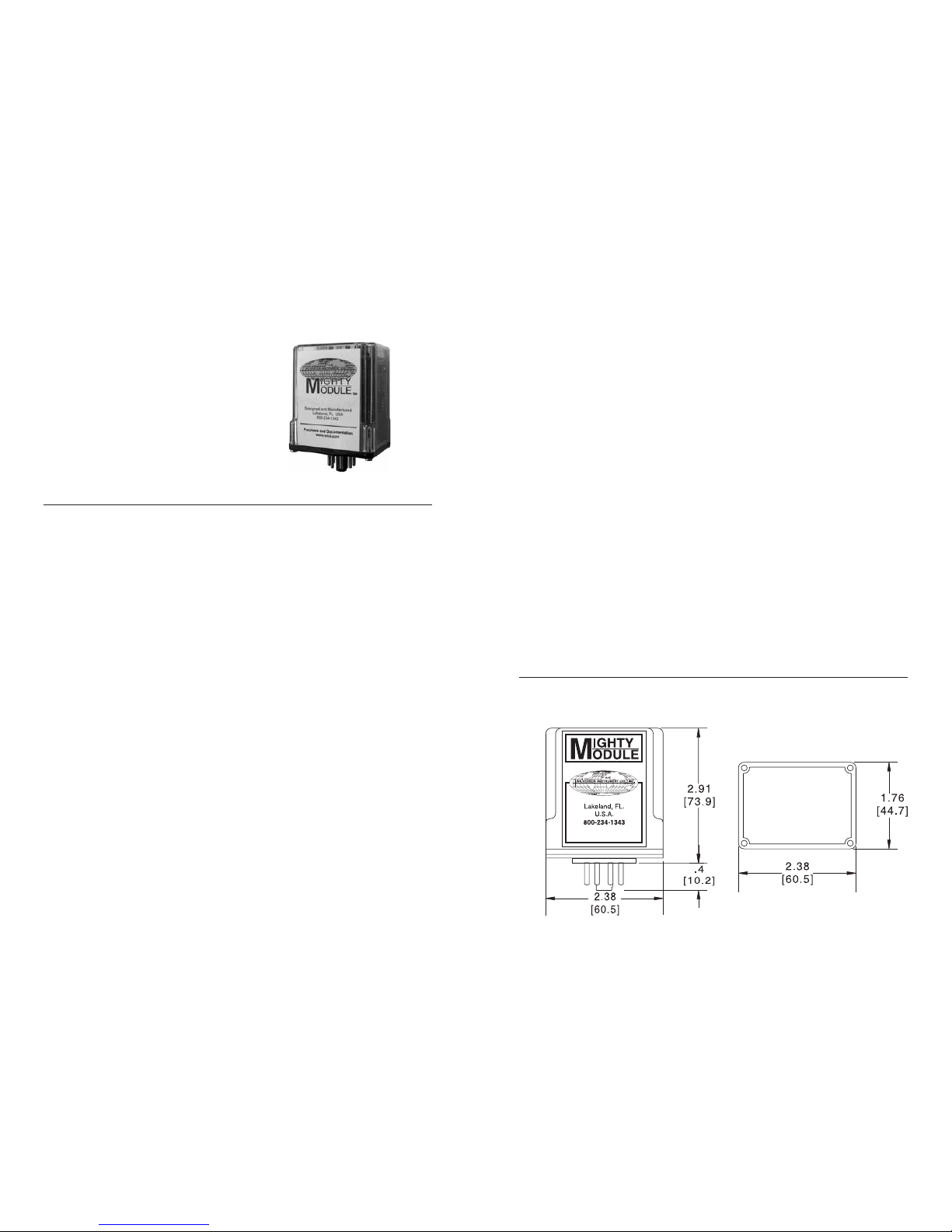
CASE DIMENSIONS INCHES [mm]
MOUNTING
The module is designed to plug into a standard
8-pin relay socket. (MP008) is a molded
plastic socket suitable for mounting on a flat
surface or snap into a 2¾ inch wide PVC
track (TRK48).
A spring hold-down clip (CLP1) is available
for installation where vibration may be a
problem.
A DIN rail mounted socket (DMP008) is
available for 35mm symmetrical DIN rail.
A Killark HK Series explosion-proof housing
with dome and 8-pin socket is available
(HKB-HK2D-8).
WARRANTY
The Mighty Module Series of products carry
a limited warranty of 10 + 5 years. In the
event of a failure due to defective material
or workmanship, during the 10 year period,
the unit will be repaired or replaced at no
charge. For a period of 5 years after the
initial 10 year warranty, the unit will be
repaired, if possible, for a cost of 10 % of
the original purchase price. Relays are not
covered by the warranty.
1 2
Page 2
SPECIFICATIONS
INPUT RANGE
select any range from
0 to 10 Hz min
to 0 to 60 kHz max
INPUT SENSITIVITY
any voltage from 50 mV
to 100 V peak
INPUT IMPEDANCE
100 kilohms
OUTPUT RANGE
Voltage
select any range from
–10 V to +15 V,
10 mA max load
(min span 0.2 V)
Current
select any range from
0 to 20 mA max
24 V compliance*
(min span 1 mA)
ACCURACY
±0.1% of span
LINEARITY
±0.1% of span
COMMON MODE REJECTION
120 dB, DC to 60 Hz
ISOLATION (ISO OPTION)
Output/Input
>500 megohms
Breakdown Voltage
>1000 VAC rms
BREAKDOWN,
PWR/CIRCUITRY
>1500 VAC rms
OPERATING TEMPERATURE
14°F to 140°F
–10°C to 60°C
TEMPERATURE STABILITY
±0.02% of span/°C max
OPTION P
Pullup resistor to + input
10 kilohms to +5 VDC
Open-circuit voltage
+5 VDC
POWER
115 VAC ±10%,
50 or 60 Hz
(2.5 W max)
230 VAC ±10%,
50 or 60 Hz
(2.5 W max)
(DC Power Option)
12 VDC
(limits 10 VDC to 15 VDC)
(2.5 W max)
24 VDC
(limits 21 VDC to 32 VDC)
(2.5 W max)
Isolation, DC power
supply to input
common: >500 megohms
* Compliance: The sum of all
voltage drops in the output loop
cannot exceed 24 V at rated
current (1200 ohms @ 20 mA).
Specifications are subject to change without notice. ©2007 Wilkerson Instrument Co., Inc. DWG#W101041D 3/07
3 4
 Loading...