

Page 1
MM4300A
ISOLATED DC TO DC
TRANSMITTER
ADJUSTMENTS
The isolated transmitter is precisely
calibrated at the factory and does not
normally require user calibration. If
there is a need to recalibrate, proceed
as follows:
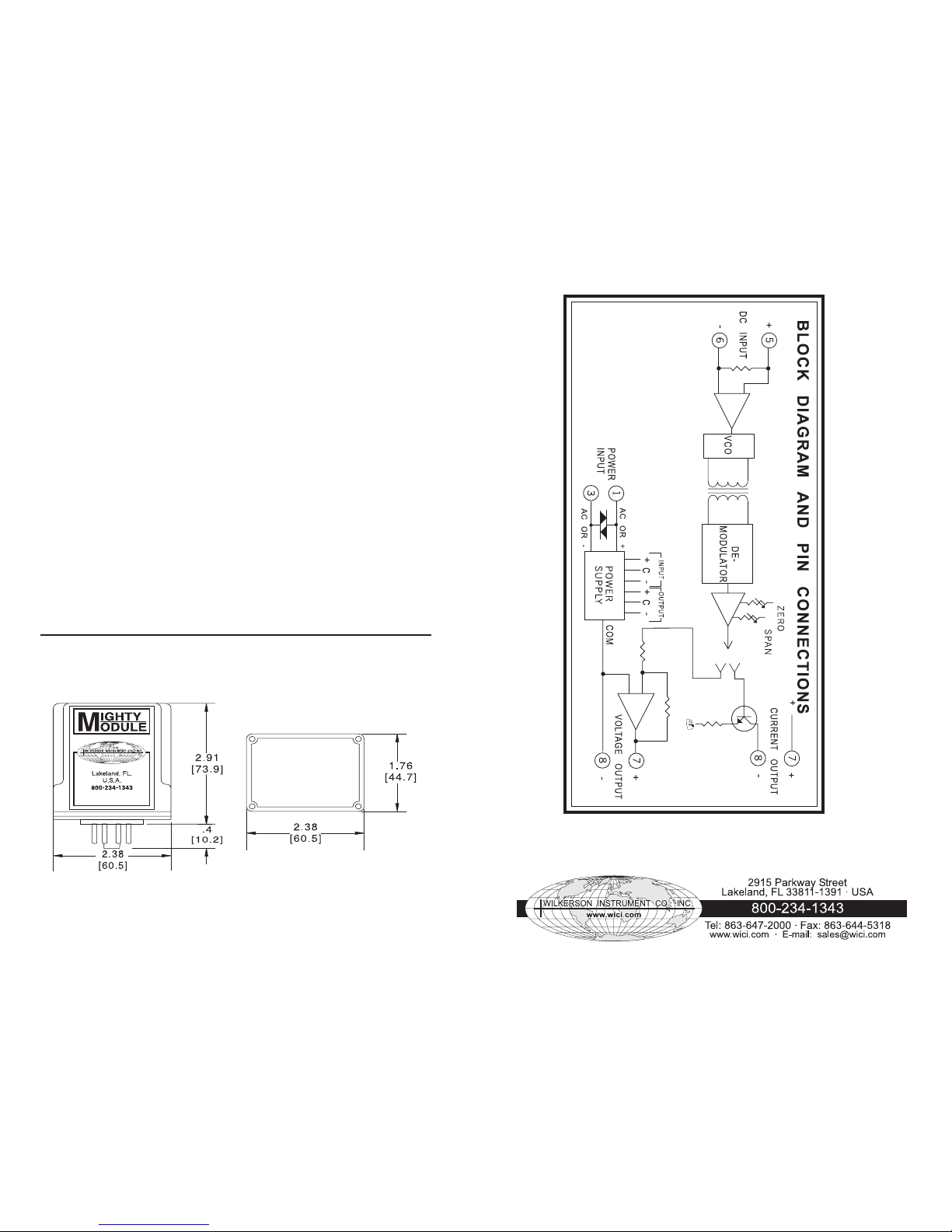
Connect a calibrated source to the
module input [terminals 5 (+) and 6
(-)].
Monitor the output of the module
[terminals 7 (+) and 8 (-)] with an
accurate digital meter.
Set the input signal to its low end, or
zero, value and adjust the ZERO control
to the proper low end output.
Increase the input signal to its full
scale value and adjust the SPAN
control for the high end output signal.
Repeat the procedure once or twice,
the controls may interact slightly.
FUNCTION
The MM4300A provides a DC output,
fully isolated from input, line power
and ground, proportional to a DC
input. It is useful in eliminating ground
loops and common mode signals.
The module includes filtering and
conditioning to reduce susceptibility
to transients and noisy operations.
They utilize pulse width modulation
to develop a pulse train with a duty
cycle proportional to the input signal
amplitude. This pulse train is coupled
through a pulse transformer where
the duty cycle data is converted to a
proportional DC level in the output
circuit.
TYPICAL APPLICATIONS
Eliminates ground loops and large
common mode signals. Use for
voltage/current scaling and
conversion with isolation for buffering
and noise reduction.
CALIBRATION CONTROLS
The MM4300A Isolator contains two
calibration controls, zero and span
(gain). These controls are accessed
through the holes at the top of the
Mighty Module case, and are screw
driver adjusted.
ISOLATION, OUTPUT/INPUT
BREAKDOWN
>500 megohms,
>1000 VAC rms
BREAKDOWN,
POWER / CIRCUITRY
>1500 VAC rms
OPERATING TEMPERATURE
14°F to 140°F/
-10°C to 60°C
TEMPERATURE STABILITY
±0.02% of span
+30 µV/°C max
POWER
115 VAC ±10%,
50 or 60 Hz (2.5 W max)
24 VAC ±10%,
50 or 60 Hz (2.5 W max
230 VAC ±10%,
50 or 60 Hz (2.5 W max)
24 VAC ±10%,
50 or 60 Hz (2.5 W max)
(DC Power Option)
12 VDC
(limits 10 VDC to 15 VDC)
(2.5 W max)
24 VDC
(limits 21 VDC to 32 VDC)
(2.5 W max)
*Compliance:
The Sum of all voltage drops in the
output loop cannot exceed 24 V at
rated current (1200 ohms @ 20 mA).
SPECIFICA TIONS
INPUT RANGES
4/20mA or 0/10VDC
INPUT IMPEDANCE
Voltage
200 kilohms
Current
50 ohms
OUTPUT RANGE
Voltage
0/+10 VDC,
2 kilohms minimum load
Current
4/20 mA,
24 V compliance*
RESPONSE TIME
£100 ms
OUTPUT RIPPLE
(peak-to-peak)
<0.1% of span
ACCURACY
±0.1% of span
LINEARITY
±0.05% of span
COMMON MODE REJECTION
120 dB, DC to 60 Hz
1 2
Page 2
MOUNTING
The module is designed to plug into
a standard 8-pin relay socket.
(MP008) is a molded plastic socket
suitable for mounting on a flat surface
or snap into a 2 3/4 inch wide PVC
track (TRK48).
A spring hold-down clip (CLP1) is
available for installation where
vibration may be a problem.
A DIN rail mounted socket (DMP008)
is available for 35mm symmetrical
DIN rail.
A Killark HK Series explosion-proof
housing with dome and 8-pin socket
is available (HKB-HK2D-8).
WARRANTY
The Mighty Module Series of products
carry a limited warranty of 10 + 5
years. In the event of a failure due to
defective material or workmanship,
during the 10 year period, the unit
will be repaired or replaced at no
charge. For a period of 5 years after
the initial 10 year warranty, the unit
will be repaired, if possible, for a
cost of 10 % of the original purchase
price.
Relays are not covered by the
warranty.
CASE DIMENSIONS INCHES [mm]
Specifications Are Subject To Change Without Notice. © 2007 Wilkerson Instrument Co., Inc. DWG#102453C 3/07
3
4
 Loading...