

Page 1
FUNCTION
The MM4010, MM4050, MM4300 and MM4310
DC to DC Transmitters provide DC output
voltages or currents proportional to a DC
input signal. They are useful in converting
voltages to currents or currents to voltages,
in providing signal isolation and in scaling
signal levels from one amplitude to another.
DESCRIPTION
A stable amplifier is used to monitor a DC
input voltage. For current inputs a shunt
resistor is added inside the module to create
a voltage level at the amplifier input. A final
amplifier produces the desired DC voltage or
current output.
The modules include filtering and conditioning to reduce susceptibility to transients and
noisy operations.
MM4300 and MM4310 utilize pulse width
modulation to develop a pulse train with a
duty cycle proportional to input signal amplitude. This pulse train is coupled through a
pulse transformer where the duty cycle data
is converted to a proportional DC level in the
output circuit.
A wide range input option adds an 10 position
DIP switch which provides input voltage and
current range selection by connecting any
of 6 gain-setting and 2 current-shunt
resistors.
MODEL NUMBERS
Transmitters are available with or without
input isolation and with standard or narrow
spans. The narrow span models use a
superior, low drift input amplifier. Model
numbers are as follows:
MM4010 Standard spans, nonisolated
MM4050 Narrow spans (below 50 mV),
nonisolated
MM4300 Standard spans, input-output
isolated
MM4310 Narrow spans (below 50 mV),
input-output isolated
OPTIONS
WR Wide range input. Allows a choice of
input voltage and current range
selections by use of an 10 position DIP
switch.
U All circuit boards conformal coated for
protection against moisture.
DC Power 12 or 24 VDC.
RT Reverse acting transmitter.
The transmitter output decreases as
the input increases. (MM4300,
MM4310 only)
MM4010, MM4050,
MM4300 & MM4310
DC TO DC
TRANSMITTERS
CONTROLS
The DC to DC transmitters contain two
calibration controls, zero and span (gain).
The WR option adds an 10 position DIP
switch for range selection.
CALIBRATION
The transmitters are precisely calibrated at
the factory and do not normally require user
calibration. If there is a need to recalibrate,
proceed as follows:
If your transmitter includes the WR option,
remove its cover and set the 10 DIP switches
according to the table below.
ZERO and SPAN adjustments are available
on top of the transmitter module. Connect a
calibrated signal source to the module input.
Monitor the output of the module with an
accurate digital meter. Set the input signal to
its zero or low value and adjust the ZERO
control for the proper output. Increase the
input signal to its full scale value and adjust
the SPAN control for the proper output.
Repeat the procedure once or twice, the
controls may interact slightly.
MOUNTING
The module is designed to plug into a standard
8-pin relay socket. MP008 is a molded plastic
socket suitable for mounting on a flat surface
or snap into a 2 3/4 inch wide PVC track
TRK48.
A hold-down clip , CLP1, is available for
installation where vibration may be a problem.
A DIN rail mounted socket, DMP008, is available
for 35mm symmetrical DIN rail.
A Killark HK Series explosion-proof housing
with dome and 8-pin socket is available,
HKB-HK2D-8.
WARRANTY
The Mighty Module Series of products carry
a limited warranty of 10 + 5 years. In the
event of a failure due to defective material
or workmanship, during the 10 year period,
the unit will be repaired or replaced at no
charge. For a period of 5 years after the
initial 10 year warranty, the unit will be
repaired, if possible, for a cost of 10 % of
the original purchase price.
Relays are not covered by the warranty.
WIDE RANGING INPUT (WR OPTION)
INPUT CLOSE SWITCH INPUT CLOSE SWITCH
POSITION # POSITION #
0/50 mV none 0/1 mA 9
0/100 mV 1 0/5 mA 10
0/500 mV 2 0/10 mA 1, 10
0/1 V 3 4/20 mA 7. 9
1/5 V 6 0/20 mA 3, 9
0/5 V 4 10/50 mA 8, 10
0/10 V 5 0/50 mA 2, 10
1 2
Page 2
SPECIFICATIONS
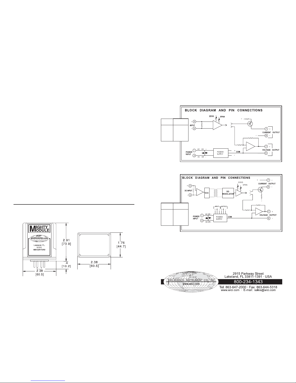
INPUT IMPEDANCE
Voltage 200 kilohms
Current see table on block diagram
INPUT RANGE
MM4010 Select any range between
±10 V max
(min span 50 mV)
MM4050 Select any range between
±10 V max
(min span 10 mV)
MM4300 Select any range between
±250 V max
(min span 50 mV)
MM4310 Select any range between
±20 V max
(min span 10 mV)
Current MM4010, MM4050, MM4300,
MM4310 select any range
between ±5 A max
(min span 1 mA)
OUTPUT LIMITS
Voltage -10 to +15 V, 10 mA
Current 50 mA, 24 V compliance
LINEARITY
MM4010, MM4050
±0.01% of Span
MM4300, MM4310
±0.05% of Span
CASE DIMENSIONS INCHES [mm]
OUTPUT RIPPLE
MM4300, MM4310
less than 0.1% of Span peak to peak
ACCURACY
±0.1% of span
COMMON MODE REJECTION
120 dB, DC to 60 Hz
ISOLATION, OUTPUT/INPUT
BREAKDOWN
(MM4300, MM4310)
>500 megohms
>1000 VAC rms
BREAKDOWN, PWR/CIRCUITRY
>1500 VAC rms
OPERATING TEMPERATURE
14°F to 140°F (-10°C to 60°C)
TEMPERATURE STABILITY
±(0.02% of span +1.3 microvolt/°C max
POWER
Standard
115 VAC ±10%, 50/60 Hz
Optional
230 VAC ±10%, 50/60 Hz
12 or 24 VDC (2.5 W max)
MM4010/4050
Specifications are subject to change without notice. ©2007 Wilkerson Instrument Co., Inc. DWG#W102308B 3/07
MM4300/4310
Current Input
Input Shunt Value
1 mA 100 ohm
10 mA 10 ohm
20 mA 5 ohm
4/20 mA 61.9 ohm
100 mA 1 ohm
1 A 0.1 ohm
5 A 0.01 ohm
Current Input
Input Shunt Value
1 mA 100 ohm
10 mA 10 ohm
20 mA 5 ohm
4/20 mA 61.9 ohm
100 mA 1 ohm
1 A 0.1 ohm
5 A 0.01 ohm
3
4
 Loading...