

Page 1
DESCRIPTION
The MM1700 monitors a frequency input
signal and trips a dpdt, 5 A relay when the
input exceeds the desired level. Normal
operation has the relay energized for the
non-alarm condition and de-energized for an
alarm condition. This provides a fail-safe
alarm condition for loss of power to the
module. The alarm has a set of red/green
LEDs to indicate alarm status.
A deadband adjustment allows a deadband
of 0.5% to 100% of span to be set into the
module. The deadband is symmetrical about
the setpoint.
With the latching option, the alarm has no
deadband control. Once the limit has been
reached the alarm latches and power to the
module must be momentarily interrupted to
reset the alarm.
The wide range of input sensitivity allows
the MM1700 Series alarms to be driven from
low level magnetic pickups as well as logic
level signals. A threshold adjustment sets
the minimum input amplitude the module will
process. This allows the user to trade off
sensitivity versus noise rejection. An optional
pullup resistor (Option P) permits use with
contact-closure or open-collector inputs.
The module includes filtering and conditioning
to reduce susceptibility to transients and
noisy operations.
MODEL NUMBERS
These instructions cover the following
setpoint styles:
MM1700 Frequency Input Single Alarm
(25 turn screwdriver adjust)
MM1701 Frequency Input Single Alarm
(Single turn dial)
MM1704 Frequency Input Single Alarm
(Ten turn precision dial)
OPTIONS
These instructions cover the following
options on the MM1700 Series. Options
installed are listed on the label attached to the
side of the module.
H/L H = High alarm: Alarm occurs on an
increasing signal
L = Low alarm: Alarm occurs on a
decreasing signal
R The Normal condition for the relay is
energized. It de-energizes for an alarm
condition (Failsafe). Option R (Reverse
Sense) reverses this logic.
P 10 kilohm pullup resistor for use with
open-collector or contact-closure
inputs.
U All circuit boards conformal coated for
protection against moisture.
MM1700, MM1701 and
MM1704
FREQUENCY INPUT
SINGLE ALARMS
CONTROLS
The MM1700, MM1701 and MM1704 modules
contain setpoint, deadband, zero, span and
threshold adjustments. The setpoint control
in the MM1700 is a 25-turn blind trimpot.
MM1701 and MM1704 contain 1-turn and
10-turn calibrated dials, respectively.
CALIBRATION
Modules are shipped with ZERO and SPAN
precalibrated. The THRESHOLD adjustment
also has been set per requirements stated
on the initial order. The user needs only
adjust the SETPOINT for the desired
response.
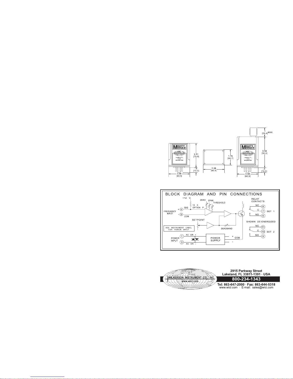
Connect the input to a precision frequency
source covering the desired input range.
Refer to the instrument’s label to determine
your instrument’s supply voltage and input
range. Refer to the “Block Diagram and Pin
Connections” for connections.
To calibrate the alarm setpoint, set the input
to the desired setpoint and turn the
DEADBAND control fully ccw. Adjust the
SETPOINT control until the LED switches to
red (ccw for a high alarm, cw for low).
Adjust the DEADBAND control for the desired
amount of deadband. Vary the input up and
down to check the level at which the alarm
trips and resets. The setpoint will
remainapproximately centered in the middle
of the deadband.
The THRESHOLD adjustment allows the
module to be made insensitive to line
frequency pickup or other noise signals
whose levels are below the threshold
setting. Turning this control fully clockwise
reduces the threshold to zero and makes
the input most sensitive. To adjust, set the
input at about 25% of its normal amplitude.
Set the input frequency to a value slightly
above the trip point. This will cause a high
alarm to trip, or a low alarm to reset.
Start with the THRESHOLD adjustment fully
counterclockwise (minimum sensitivity).
Turn the THRESHOLD adjustment cw until
the alarm changes state. A HIGH alarm will
trip; a LOW alarm will reset.
It is not necessary to recalibrate the setpoint
after changing the threshold setting.
If there is a need to recalibrate ZERO and
SPAN, proceed as follows:
Set the input to the low end of the input range.
Turn the SETPOINT and DEADBAND controls
fully ccw. Adjust the ZERO control until the
LED color changes.
Change the input to the high end of the input
range. Turn the SETPOINT control fully cw.
Adjust the SPAN control until the LED color
changes.
Repeat the ZERO and SPAN adjustments
until both are correct.
After calibration, the SETPOINT and
DEADBAND controls should be reset as
described above.
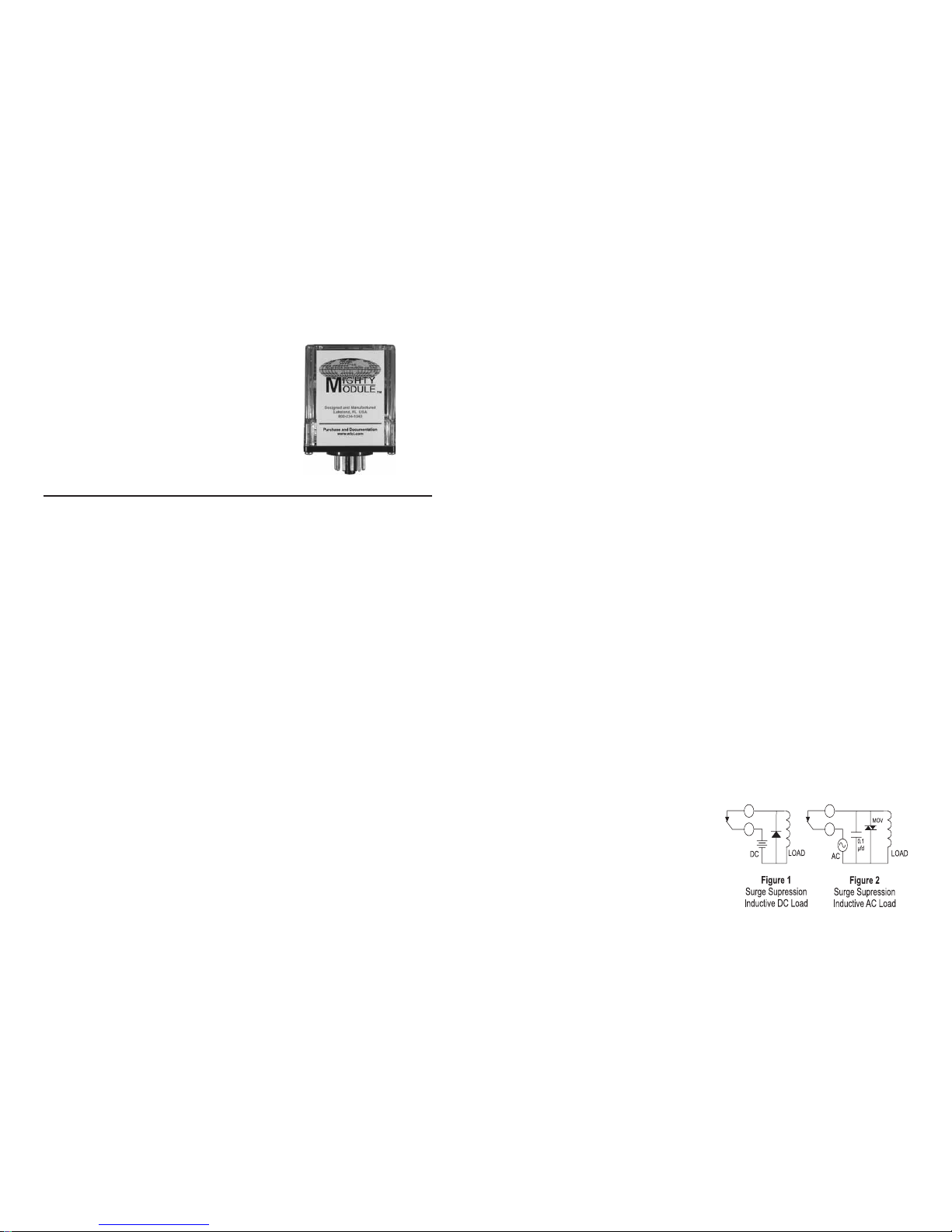
RELAY CONTACT PROTECTION
When inductive loads such as motors, relays
or transformers are switched, voltage
transients may be generated which exceed
the ratings of the relay contacts. The resulting
arcing can quickly destroy the contacts.
(Refer to the SPECIFICATIONS below for the
relay contact ratings.)
Surge suppression is required across
inductive loads to guard against premature
relay failure. Figure 1 illustrates diode surge
suppression for a DC load. The diode’s
operating (peak inverse) voltage should
exceed the load’s supply voltage by at least
50% and should have a current rating of at
lease one ampere.
Figure 2 shows surge suppression for an
AC load, using an MOV (metal oxide varistor)
and a capacitor. The breakdown voltage
ratings of both the MOV and the capacitor
must exceed the peak AC voltage.
With normal sine-wave power, PEAK = 1.414
x RMS voltage. For 115 VAC power, a 200
volt peak rating is recommended.
1 2
Page 2
SPECIFICATIONS
Input Range
select any range from 0 to 10 Hz min
to 0 to 60 kHz min
Input Sensitivity
any voltage from 50 mV to 100 V peak
Input Impedance
100 kilohms
Option P
Pullup resistor to + input 10 kilohms
Open circuit voltage +12 VDC
Setpoint
0 to 100% of span
Deadband
0.5% to 100% of span
Accuracy
±0.1% of span
Common Mode Rejection
120 dB, DC to 60 Hz
Relay Contacts (dpdt)
Resistive Load:
5 A max, 150 W max,
220 VAC max, 30 VDC max
Inductive Load:
(Power Factor => 0.4)
2.5 A max, 75 W max,
220 VAC max, 30 VDC max
Transistor Output
(Option V)
Relay drive (12 V coil, ±220 ohms)
or open collector outputs sink 100 mA,
30 V supply max
Operating Temperature
14°F to 140°F / -10°C to 60°C
Temperature Stability
±0.2% of span/°C max
Power
115 VAC ±10%, 50/60 Hz (2.5 W max)
230 VAC ±10%, 50/60 Hz (2.5 W max)
(DC Power Option) (2.5 W max)
12 VDC (limits 10 VDC to 15 VDC)
24 VDC (limits 21 VDC to 32 VDC)
Isolation, DC power supply to input
common: 10 megohms
MM1700 MM1701 & MM1704
Specifications are subject to change without notice. © 2008 Wilkerson Instrument Co., Inc. DWG#101717D 3/15
MOUNTING
MM1700, MM1701 and MM1704 are designed
to plug into a standard 11-pin relay socket.
(MP011) is a molded plastic socket suitable
for mounting on a flat surface or
2 3/4 inch wide PVC snap track (TRK48).
Use (CLP1) hold-down clip if needed.
CASE DIMENSIONS INCHES [mm]
A Killark HK Series explosion-proof housing
with dome and 11-pin socket is available
(HKB-HK2D-11). A DIN rail mounted socket
(DMP011) is available for 35mm symmetrical
rail.
3
4
 Loading...