

Page 1
DESCRIPTION
The MM1420 Series RTD input alarms monitor an RTD (resistance thermometer) input
and provide two sets of SPDT, 5A alarm
relays with two independently adjustable
setpoints. Each setpoint has a set of red/
green LEDs to indicate alarms status. When
the input is between the setpoints, the relays
are normally de-energized. When the signal
exceeds a particular setpoint, the relay becomes energized.
Each module can be supplied as a HI/HI, HI/
LO, or LO/LO alarm (HI/LO supplied if not
specified). To provide a “fail-safe” operation
(loss of power resulting in an alarm state),
select Option R.
Standard deadband on both alarms is fixed
at 0.5% of span. (Option A provides adjustable deadband of 0.5% to 100% span.)
Option D, latching alarms, has no deadband
control. Once the limit has been reached the
alarm latches and power to the module must
be momentarily interrupted to reset the alarm.
The modules include filtering and conditioning to reduce susceptibility to transients and
noisy operations.
MODEL NUMBERS
These instructions cover the following
setpoint styles:
MM1420 RTD Input Dual Alarm
(25 turn screwdriver adj)
MM1421 RTD Input Dual Alarm
(Single turn dials)
MM1424 RTD Input Dual Alarm
(Ten turn precision dials)
OPTIONS
These instructions cover the following options on the MM1420. Options installed are
listed on the label attached to the side of the
module.
A Provides top accessed screwdriver ad-
justable deadbands from 0.5% to 100%
of span, instead of the normal fixed 0.5%
deadbands.
D Latching alarms. Reset by momentary
interruption of line power.
DC Power Inverter isolated 12 or 24 VDC
power.
E 11-pin header instead of standard 20-
pin. Available only on MM1420, MM1421
and MM1424 without Option T.
R The Normal condition for the relays is
de-energized. They energize for alarm
conditions. Option R (Reverse sense)
reverses this logic (Failsafe).
U All circuit boards conformal coated for
protection against moisture.
CONTROLS
The MM1420, MM1421 and MM1424 modules
contain two setpoint controls, plus zero and
span adjustments. The setpoint controls in
the MM1420 are 25-turn blind trimpots.
MM1421 and MM1424 contain 1-turn and 10turn calibrated dials, respectively. Option A,
adjustable deadband, adds two deadband
trimpots.
CALIBRATION
Modules are shipped with ZERO and SPAN
precalibrated. The user needs only adjust
the SETPOINTS and optional DEADBANDS
for the desired levels.
MM1420, MM1421 &
MM1424
RTD INPUT
DUAL ALARMS
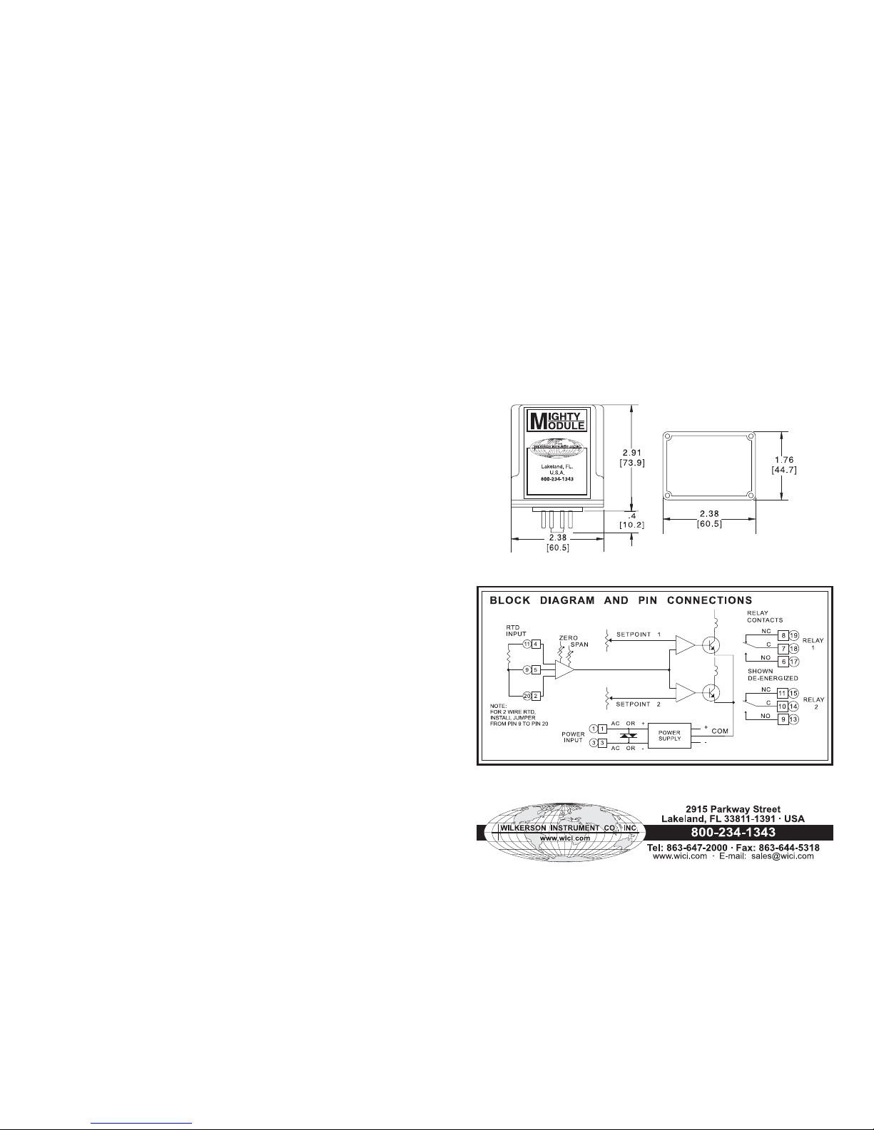
Refer to the instrument’s label to determine
your instrument’s supply voltage and input
and output ranges. Refer to the “Block
Diagram and Pin Connections” for connections. 20-pin and 11-pin styles both are
shown.
Connect a precision decade resistance,
potentiometer or RTD simulator to the input.
To avoid errors due to the resistances of the
connecting wires, use a three-wire connection as shown in the “ Block Diagram and Pin
Connections”.
(Note: When calibrating latching alarms,
Option D, it will be necessary to momentarily
interrupt power to reset the alarm after each
trip.)
To calibrate the alarm setpoints, begin with
the optional DEADBAND controls turned fully
ccw. Adjust the input resistance to the
desired alarm 1 setpoint. Adjust the SETPOINT
1 control until its LED just turns red (ccw for
a high alarm, cw for low).
Change the input resistance to the desired
alarm 2 setpoint and similarly adjust the
SETPOINT 2 control.
The MM1421 (single turn dial) and MM1424
(10-turn dial) may be set using their 0-100%
dials.
Adjust the optional DEADBAND controls for
the desired amount of deadband. Vary the
input signal up and down to check the levels
at which the relay trips and resets. The
setpoint will remain approximately centered
in the middle of the deadband.
If there is a need to recalibrate ZERO and
SPAN, turn the optional DEADBAND controls
fully ccw and proceed as follows:
Set the resistance to the low end of the input
range. Turn the SETPOINT 1 control fully
ccw. Adjust the ZERO control until the
SETPOINT 1 LED just changes color.
Change the resistance to the high end of the
input range. Turn the SETPOINT 2 control
fully cw. Adjust the SPAN control until the
SETPOINT 2 LED just changes color.
Repeat until the ZERO and SPAN settings
both are correct.
After adjusting the ZERO and SPAN controls, the SETPOINT and DEADBAND controls should be reset as described above.
RELAY CONTACT PROTECTION
When inductive loads such as motors, relays
or transformers are switched, voltage transients may be generated which exceed the
ratings of the relay contacts. The resulting
arcing can quickly destroy the contacts.
(Refer to the SPECIFICATIONS below for the
relay contact ratings.)
Surge suppression is required across inductive loads to guard against premature relay
failure. Figure 1 illustrates diode surge suppression for a DC load. The diode’s operating
(peak inverse) voltage should exceed the
load’s supply voltage by at least 50% and
should have a current rating of at least one
ampere.
Figure 2 shows surge suppression for an AC
load, using an MOV (Metal Oxide Varistor)
and a capacitor. The breakdown voltage
ratings of both the MOV and the capacitor
must exceed the peak AC voltage.
With normal sine-wave power, PEAK = 1.414
x RMS voltage. For 115V AC power a 200 volt
peak rating is recommended.
ALARM TYPE HI/LO HI/HI LO/LO
SETPOINT 1 HI HI LO
SETPOINT 2 LO HI LO
1 2
Page 2
SPECIFICATIONS
RTD INPUT
3-Wire or 2-Wire,
10 ohms to 2000 ohms
INPUT RANGE
select any range within RTD limit
[min span 25°F/14°C
(100°F/55°C with 10 ohms RTD)]
EXCITATION CURRENT
10 ohms 10 mA
100 ohms 5 mA
1000 ohms 0.5 mA
2000 ohms 0.2 mA
SETPOINT
each alarm 0 to 100% of span
DEADBAND
Standard
fixed 0.5% of span
(Option A)
0.5% to 100% of span
(Option D)
Latching. Interrupt power to reset.
OPEN SENSOR OUTPUT
³ full scale
ACCURACY
±0.1% of span or 0.02 ohms,
whichever is greater
COMMON MODE REJECTION
120 dB, DC to 60 Hz
RELAY CONTACTS (spdt)
Resistive Load:
5 A max, 150 W max, 240 VAC max,
30 VDC max
Inductive Load:
1
/8 HP max at 120/240 VAC
OPERATING TEMPERATURE
14°F to 140°F/–10°C to 60°C
TEMPERATURE STABILITY
±0.02% of span or 0.025°C/°C,
whichever is greater
POWER
115 VAC ±10%, 50 or 60 Hz
(2.5 W max)
230 VAC ±10%, 50 or 60 Hz
(2.5 W max)
(DC Power Option)
12 VDC (limits 10 VDC to 15 V DC)
(2.5 W max)
24 VDC (limits 21 VDC to 32 V DC)
(2.5 W max)
Isolation, DC power supply to input
common: 10 megohms
* Within specified range limits.
CASE DIMENSIONS INCHES (mm)
WARRANTY
Contact the factory 1-800-234-1343.
MOUNTING
MM1420, MM1421 and MM1424 are designed to plug into a standard 20-pin relay socket.
(Option E requires an 11-pin socket.) MP020 and MP011 are 20-pin and 11-pin sockets
suitable for mounting on a flat surface. MP011 may also be mounted in a piece of PVC track.
A DIN-rail mounted socket, DMP011, is available for 35mm symmetrical rail.
Specifications are subject to change without notice. ©2008 Wilkerson Instrument Co., Inc. DWG#101034C 3/15
3 4
 Loading...