

Page 1

DESCRIPTION
The MM1200 monitors any thermocouple input
signal and trips a dpdt, 5 A relay when the
input exceeds the desired level. Normal
operation has the relay energized for the nonalarm condition and de-energized for an alarm
condition. This provides a fail-safe alarm
condition for loss of power to the module. The
alarm has a set of red/green LEDs to indicate
the alarm status.
A deadband adjustment allows a deadband of
0.5% to 100% of span to be set into the
module. The deadband is symmetrical about
the setpoint.
With the latching option, the alarm has no
deadband control. Once the limit has been
reached, the alarm latches and power must
be momentarily interrupted to reset the alarm.
Cold junction compensation is provided by a
solid state temperature sensor embedded in
the thermocouple terminal strip. The module
includes filtering and conditioning to reduce
susceptibility to transients and noisy
operations.
Upscale burnout protection is provided as
standard. In the event the thermocouple
opens, the module behaves as though the
input goes offscale high.
Option B provides downscale burnout
protection (module behaves as though
the input goes low).
OPTIONS
H High alarm: Alarm occurs on an
increasing signal.
L Low alarm: Alarm occurs on a
decreasing signal.
R The Normal condition for the relay is
energized. It de-energizes for an alarm
condition (Failsafe). Option R (Reverse
Sense) reverses this logic.
U All circuit boards conformal coated for
protection against moisture.
V Relay driver output (12VDC unfiltered).
For use with 12 VDC relay coils having
220 ohms resistance. Also suitable for
use as open-collector output.
B Standard burnout protection is upscale
(high temperature). Option B provides
downscale (low temperature)
indication on thermocouple burnout.
MM1200
THERMOCOUPLE INPUT
LIMIT ALARMS
CALIBRATION
The module is shipped with ZERO and SPAN
precalibrated. The user needs only adjust
the SETPOINT and DEADBAND for the desired
levels.
Known input must be provided for setpoint
adjustment and for calibration. If a
thermocouple simulator is available, use it to
provide the input, connecting it to the module
with the appropriate pair of thermocouple
wires. Otherwise, use copper wires to
connect a precision DC millivolt source to the
input.
When a millivolt source and copper wires are
used it will be necessary to measure and
correct for the temperature at the module’s
input connection. Using standard tables for
your thermocouple, find the millivolt level
corresponding to the temperature at the input
terminals. Then, at each calibration
temperature, subtract this voltage from the
voltage given by the thermocouple table.
Remember, calibration accuracy will be no
better than the accuracy of this temperature
measurement.
Connect the signal to the module input and set
it for the desired trip point. Turn the
DEADBAND fully ccw. Adjust the SETPOINT
control until the relay just trips.
Adjust the DEADBAND for the desired amount
of deadband. Vary the signal up and down
to check the level at which the relay trips. The
setpoint will remain centered in the middle of
the deadband.
MOUNTING
The module is designed to plug into a standard
11-pin relay socket. (MP011) is a molded
plastic socket suitable for mounting on a flat
surface or snap into a 2 3/4 inch wide PVC
track (TRK48).
A hold-down assembly (CLP1) is available
for installation where vibration may be a
problem.
A DIN rail mounted socket (DMP011) is
available for 35mm symmetrical DIN rail.
A Killark HK Series explosion-proof housing
with dome and 8-pin socket is available
(HKB-HK2D-11).
1 2
Page 2
SPECIFICATIONS
INPUT RANGE
select any type thermocouple
(min span 5 mV)
SETPOINT
0 to 100% of span
DEADBAND
0.5% to 100% of span
ACCURACY
±0.1% of span
COMMON MODE REJECTION
120 dB, DC to 60 Hz
RELAY CONTACT (dpdt)
Resistive Load:
5 A max, 150 W max,
220 VAC max, 30 VDC max
Inductive Load:
(Power factor ³0.4):
2.5 A max, 75 W max,
220 VAC max, 30 VDC max
Linearity
(Option T) ±0.01% of span
OPERATING TEMPERATURE
14°F to 140°F/-10°C to 60°C
TEMPERATURE STABILITY
±(0.02% of span + 1.3 micro V)/°C max
POWER (2.5 W max)
115 VAC ±10%, 50/60 Hz
230 VAC ±10%, 50/60 Hz
(DC Power Option)
24 VDC (limits 21 VDC to 28 VDC)
Isolation, DC power supply to input
common: 10 megohms
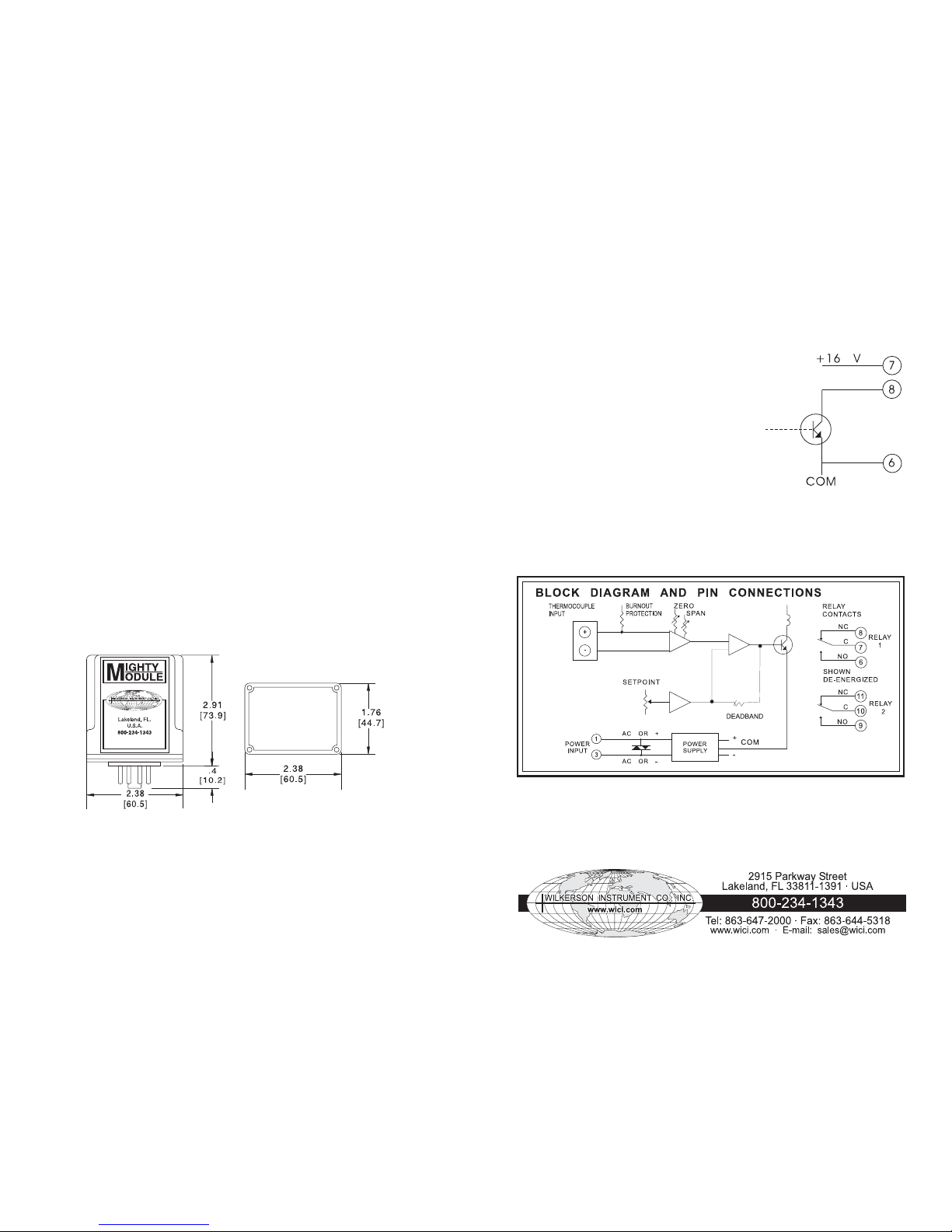
CASE DIMENSIONS INCHES [mm]
Specifications subject to change without notice. ©2007 Wilkerson Instrument Co., Inc. DWG#W102224D 3/15
V OPTION
(OPEN-COLLECTOR TRANSISTOR OUTPUT)
For TTL
(open-collector) output use:
Pins 8 (+) and 6
For relay driver
(switched voltage) output use:
Pins 7 (+) and 8
3
4
 Loading...