

Page 1
DESCRIPTION
The MM1000A is a lower-cost alternative to
the MM1000 DC limit alarm for standard
applications. The MM1000A monitors a DC
input and trips a dpdt, 5 A relay when the
input exceeds the desired level. The alarm
has a green LED to indicate relay status.
Setpoint adjustment is provided by a 25-turn
trimpot, adjustable from below 0% to above
100% of span. Deadband, also a 25-turn
trimpot, is adjustable from below 1% to
above 100% of span. A user-changeable
jumper may be changed to provide high or
low-trip.
The module includes filtering and conditioning
to reduce susceptibility to transients and
noisy operations.
For options or input ranges not provided by
MM1000A, refer to MM1000.
OPTIONS
These instructions cover the following
options on the MM1000A.
H = High alarm.
Relay de-energizes on an
increasing signal.
L = Low alarm.
Relay de-energizes on a
decreasing signal.
CONTROLS
The MM1000A contains setpoint and
deadband adjustments, both accessible from
the top of the module. A user-changeable
jumper on the circuit board may be changed
to provide high or low trip. The MM1000A has
no zero or span adjustment.
CALIBRATION
To change the SETPOINT or DEADBAND
settings proceed as follows.
To calibrate the alarm setpoint, set the input
to the desired setpoint and turn the
DEADBAND control fully ccw. Adjust the
SETPOINT control until the LED turns off (ccw
for a high alarm, cw for low).
Adjust the DEADBAND control for the desired
amount of deadband. Vary the input up and
down to check the level at which the alarm
trips and resets. The setpoint will remain
approximately centered in the middle of the
deadband.
MM1000A
DC INPUT
SINGLE ALARM
FIXED RANGE
DPDT RELAY
RELAY SETUP
To change the relay setup, unscrew the four
screws holding the cover in place. Remove
the cover to access the relay setup jumper
on the PC board.
Caution: For safety, do not apply power
while the cover is removed.
Caution: The MM1000A’s circuitry is
precise, sensitive and closely spaced.
Circuit board contamination can lead to
errors and instability, especially at high
humidities. Handle the circuit board by
its edge only, or wear clean gloves, to
avoid contamination.
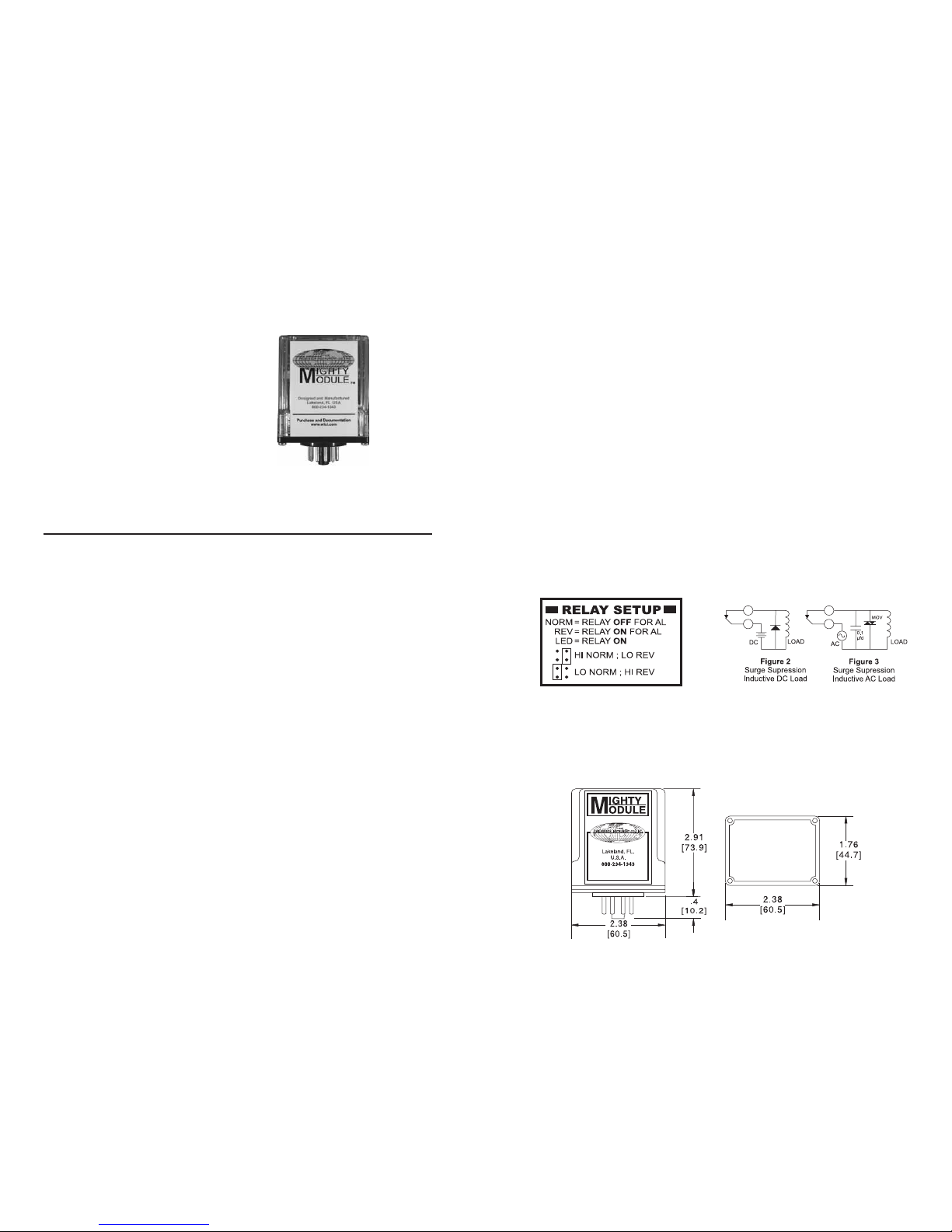
Refer to the relay setup label on the side of
the module’s cover (Figure 1). In the “HI
NORM; LO REV” position the relay will be off
(de-energized) on high inputs. In the “LO
NORM; HI REV” position the relay will be off
(de-energized) on low inputs. In either
position the LED will be on whenever the
relay is energized.
After changing the jumper position recalibrate
as described above.
Figure 1
Jumper Positions for Relay Setup
RELAY CONTACT PROTECTION
When inductive loads such as motors, relays
or transformers are switched, voltage
transients may be generated which exceed
the ratings of the relay contacts. The resulting
arcing can quickly destroy the contacts.
(Refer to the SPECIFICATIONS below for
the relay contact ratings.)
Surge suppression is required across
inductive loads to guard against premature
relay failure. Figure 2 illustrates diode surge
suppression for a DC load. The diode’s
operating (peak inverse) voltage should
exceed the load’s supply voltage by at least
50% and should have a current rating of at
least one ampere.
Figure 3 shows surge suppression for an
AC load, using an MOV (Metal Oxide Varistor)
and a capacitor. The breakdown voltage
ratings of both the MOV and the capacitor
must exceed the peak AC voltage.
With normal sine-wave power, PEAK = 1.414
x RMS voltage. For 115 V AC power a 200
volt peak rating is recommended.
CASE DIMENSIONS INCHES [mm]
1 2
Page 2
SPECIFICATIONS
INPUT RANGE
Select any input range within the
following limits
Voltage
Min span 1 V, Max input 250 V
Offset 0 V min, +100% of span max
(example, +10/+20 V)
For negative offsets, use MM1000
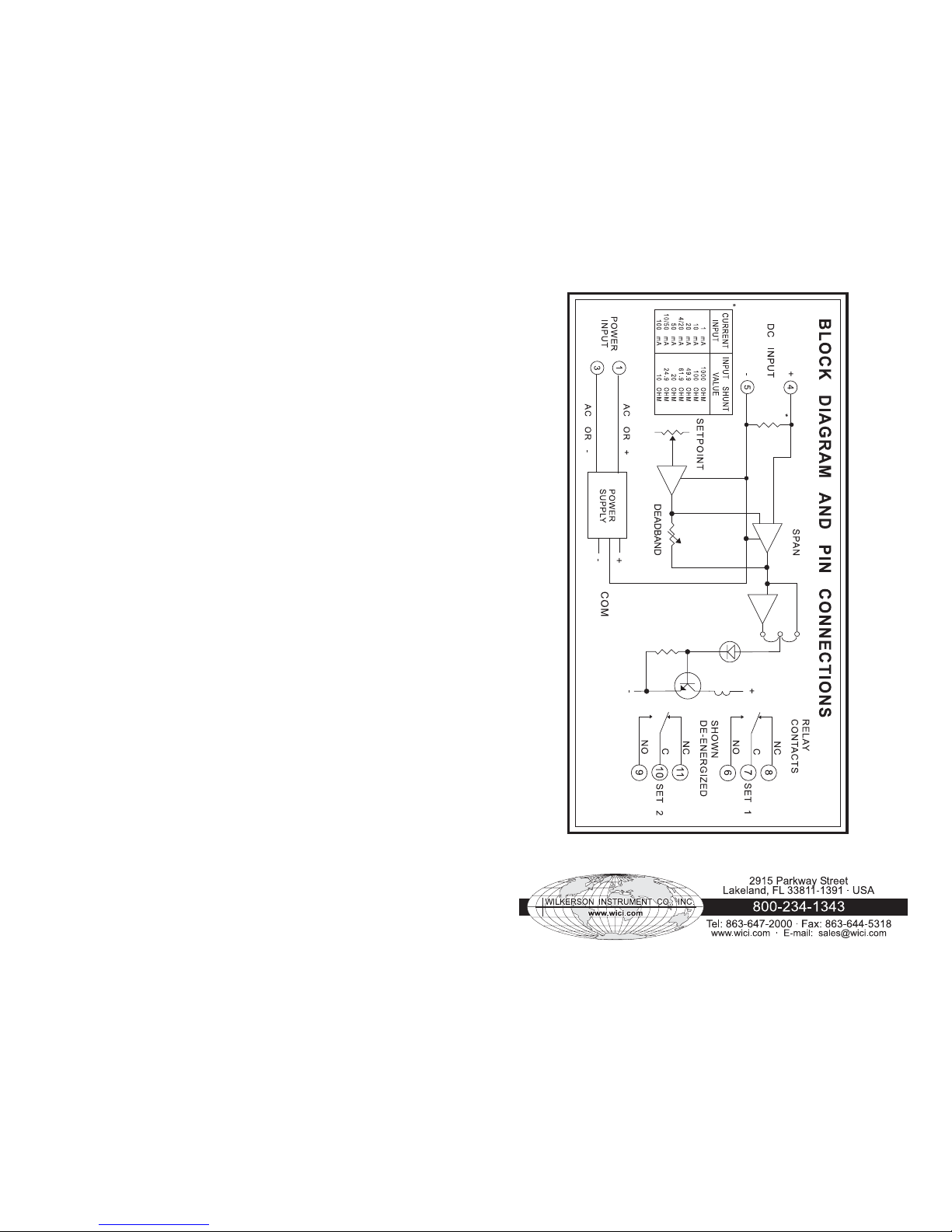
Current
Min span 1 mA, Max input 100 mA
Offset 0 mA min, 100% of span max
(example, +50/+100 mA)
For negative offsets, use MM1000.
INPUT IMPEDANCE
Voltage 200 kilohms
Current see table in block diagram
SETPOINT
0 to 100% of span, min.
DEADBAND
1% to 100 % of span, min.
RESPONSE TIME
20 ms typical
ACCURACY
±0.1% of span
COMMON MODE REJECTION
120 dB, DC to 60 Hz
RELAY CONTACTS
(dpdt)
Resistive Load:
5 A max, 150 W max, 220 VAC max,
30 VDC max
Inductive Load:
(Power factor ³ 0.4):
2.5 A max, 75 W max, 220 VAC max,
30 VDC max
OPERATING TEMPERATURE
14°F to 140°F/-10°C to 60°C
TEMPERATURE STABILITY
±0.02% of span/°C max
POWER (2.5 W max)
115 VAC ±10%, 50 or 60 Hz
230 VAC ±10%, 50 or 60 Hz
(DC Power Option)
12 VDC (limits 10 VDC to 15 VDC)
24 VDC (limits 21 VDC to 32 VDC)
Isolation, DC power supply
to input common: 10 megohms
MOUNTING
The module is designed to plug into a standard 11-pin relay socket. (MP011) is a
molded plastic socket suitable for mounting
on a flat surface or snap into a 2 3/4 inch wide
PVC track (TRK48).
A hold-down clip (CLP1) is available for
installation where vibration may be a problem.
A DIN rail mounted socket (DMP011) is available for 35mm symmetrical DIN rail.
A Killark HK Series explosion-proof housing
with dome and 11 pin socket is available
(HKB-HK2D-11).
WARRANTY
The Mighty Module Series of products carry
a limited warranty of 10 + 5 years. In the
event of a failure due to defective material
or workmanship, during the 10 year period,
the unit will be repaired or replaced at no
charge. For a period of 5 years after the
initial 10 year warranty, the unit will be
repaired, if possible, for a cost of 10 % of
the original purchase price.
Relays are not covered by the warranty.
Specifications are subject to change without notice. © 2007 Wilkerson Instrument Co., Inc. DWG#W102454 3/07
3 4
 Loading...