

Page 1
MM1520, 1521 and 1524
STRAIN GAUGE INPUT
DUAL LIMIT ALARMS
DESCRIPTION
The MM1520 Series Strain Gauge input alarms
monitor a DC input signal from a strain gauge
or bridge and provide dual setpoint alarm
outputs when the input exceeds the alarm
values. Each unit can be supplied as a HI/HI,
HI/LO or LO/LO alarm. The output relays are
normally de-energized, and energize for an
alarm condition. Two sets of red/green LED
indicate alarm status to make setup easier.
Deadband on both alarms is fixed at 0.25%
of span.
MODEL NUMBERS
These instructions cover the following
setpoint styles:
MM1520 Strain Gauge Input Dual Alarm
(25-turn screwdriver adj)
MM1521 Strain Gauge Input Dual Alarm
(Single turn dial)
MM1524 Strain Gauge Input Dual Alarm
(10-turn precision dial)
OPTIONS
These instructions cover the following options on the MM1520. Options installed are
listed on the label attached to the side of the
module.
H/H, H/L, L/L
H = High alarm.
Alarm occurs on an increasing signal.
L = Low alarm.
Alarm occurs on a decreasing signal.
NO/NC
Normally open or normally closed
relay contacts: (see specifications)
R The Normal condition for the relays is
de-energized. They energize for alarm
conditions. Option R (Reverse sense)
reverses this logic (Failsafe).
U All circuit boards conformal coated for
protection against moisture.
CONTROLS
The MM1520, MM1521 and MM1524 modules contain two setpoint controls, zero and
span adjustments, plus a bridge excitation
voltage adjustment. The setpoint control in
the MM1520 is a 25-turn blind trimpot.
MM1521 and MM1524 contain 1-turn and 25turn respectively.
CALIBRATION
Modules are shipped with ZERO, SPAN and
excitation voltage precalibrated. The user
needs only adjust the SETPOINT and
DEADBAND for the desired response.
Refer to the instrument's label to determine
your instrument's supply voltage and input
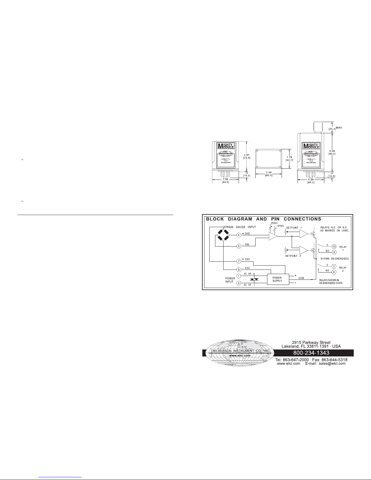
and output ranges. Refer to the "BLOCK
DIAGRAM AND PIN CONNECTIONS" for pin
connections.
Connect the alarm input to its mating input
device, or to a precision resistance bridge
capable of simulating the input device.
(If it is necessary to recalibrate using
electronic inputs, refer to the ELECTRONIC
CALIBRATION section.)
To calibrate the alarm setpoints, adjust the
input to the desired alarm 1 setpoint. Adjust
the SETPOINT 1 control until its LED switches
to red (ccw for a high alarm, cw for low).
Change the input to the desired alarm 2
setpoint and similarly adjust the SETPOINT 2
control.
If there is a need to recalibrate ZERO, SPAN
and excitation voltage, proceed as follows:
Measure the voltage between +EXC & -EXC
VOLT ADJ control for the desired excitation
voltage. The voltage is adjustable from 4 to
12 VDC.
Set the input to the low end of the input range.
Turn the SETPOINT 1 control fully ccw.
Adjust the ZERO control until the SETPOINT
1 LED color switches.
Change the input to the high end of the input
range. Turn the SETPOINT 2 control fully cw.
Adjust the SPAN control until the SETPOINT
2 LED color switches.
Repeat until the ZERO and SPAN settings are
both correct.
After adjusting the ZERO and SPAN controls,
the SETPOINT controls should be reset as
described above.
ELECTRONIC CALIBRATION
If it is necessary to recalibrate using electronic
inputs, proceed as follows:
Measure the voltage between +EXC and
-EXC using a precision digital voltmeter.
Connect a calibrated millivolt signal source
between the +SIG and -SIG inputs. Determine
the input voltage required at each calibration
point. The required voltage equals the bridge
sensitivity in millivolts per volt, multiplied by
the excitation voltage. For example, a
sensitivity of 2 mV/V multiplied by 10 V
excitation results in a 20 mV input signal.
RELAY CONTACT PROTECTION
When inductive loads such as motors, relays
or transformers are switched, voltage transients may be generated which exceed the
ratings of the relay contacts. The resulting
arcing can quickly destroy the contacts.
(Refer to the SPECIFICATIONS for the relay
contact ratings.)
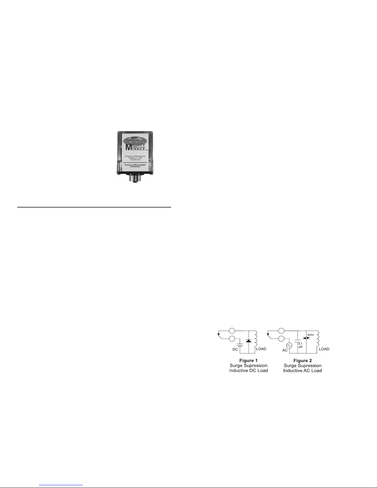
Surge supression is required across inductive loads to guard against premature relay
failure. FIGURE 1 illustrates diode surge
supression for a DC load. The diode's operating (peak inverse) voltage should exceed
the load's supply voltage by at least 50% and
should have a current rating of at least one
ampere.
FIGURE 2 shows surge suppression for an
AC load, using an MOV (Metal Oxide Varistor) and a capacitor. The breakdown voltage
ratings of both the MOV and the capacitor
must exceed the peak AC voltage.
With normal sine-wave power, PEAK = 1.414
x RMS voltage. For 115 VAC power a 200
volt peak rating is recommended.
1 2
Page 2
SPECIFICATIONS
Input Span Limits
0.5 mV/V to 1 V/V
Input Impedance
200 kilohms
Excitation
adjustable 4 V to 12 V, 40 mA max
Excitation Stability
+0.005% per °C
Deadband
0.25% to 100% of span
Setpoint (Each alarm)
0 to 100% of span
Response Time
100 milliseconds
Stability
+0.04% of span per °C
Common Mode Rejection
120 dB, DC to 60 Hz
Operating Temperature
0 °C to 60 °C / 32 °F to 140 °F
Relay Contacts (SPST)*
Resistive Load: 5 A max, 150 W max,
220 VAC max, 30 VDC max
Inductive Load : 1/8 HP max at
120/240 VAC
Power Options
115 or 230 VAC, 50 or 60 Hz
12 V or 24 VDC, 2.5 W max
*Due to pins available, only one set of
contacts is available for each relay.
WARRANTY
The Mighty Module Series of products carry
a limited warranty of 10 + 5 years. In the
event of a failure due to defective material
or workmanship, during the 10 year period,
the unit will be repaired or replaced at no
charge. For a period of 5 years after the
initial 10 year warranty, the unit will be
repaired, if possible, for a cost of 10% of
the original purchase price.
Relays are not covered by the warranty.
MOUNTING
MM1520, MM1521 and MM1524 are designed
to plug into a standard 11-pin relay socket.
(MP011) is a 11-pin socket suitable for
mounting on a flat surface or in a piece of
PVC track.
Spring holddown clips are available for installations where vibration may be a problem.
Use (CLP1) for MM1520 and (CLP2) for
MM1521 and MM1524.
A DIN rail mounted socket (DMP011) is
available for 35mm symmetrical rail.
CASE DIMENSIONS INCHES (mm)
MM1520, MM1521 and MM1524
Specifications are subject to change without notice. ©2008 Wilkerson Instrument Co., Inc. DWG#101320B 3/15
3 4
 Loading...