

Page 1
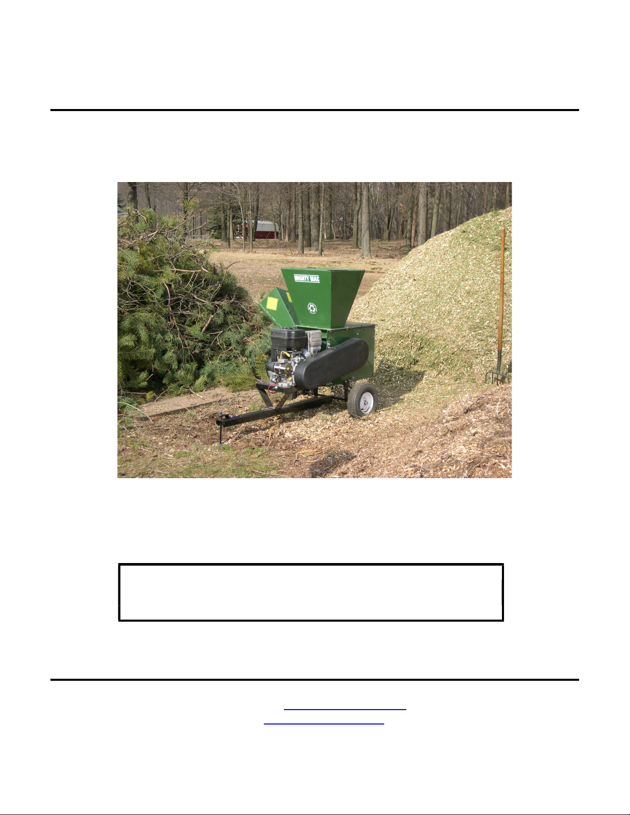
SHREDDER/CHIPPER
SAFETY AND OPERATING INSTRUCTION MANUAL
MODEL: SC1650E
This manual contains information concerning proper and improper
operation procedures, warnings, maintenance, troubleshooting, and
assembly tips. Everyone who operates this machine should read these
instructions and be thoroughly familiar with them.
MacKissic, Inc. P.O. Box 111, Parker Ford, PA 19457-0111
Phone: (610) 495-7181 e-mail: [email protected] Fax: (610) 495-5951
www.mackissic.com
P/N 910-0055
08/29/2022
Page 2
SECTION I – SAFETY
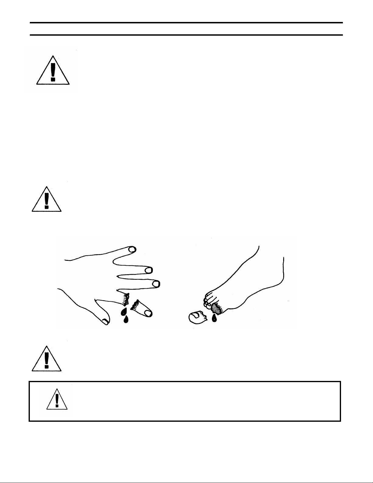
This symbol points out important safety instructions, which, if not followed,
could endanger the personal safety and/or property of yourself and others. Read and
follow all instructions in this manual before attempting to operate your
shredder/chipper. Failure to comply with these instructions may result in personal
injury. When you see this symbol - heed its warning.
THIS MACHINE IS CAPABLE OF INFLICTING SERIOUS INJURY IF
OPERATED IMPROPERLY -- READ WARNINGS & CAUTION LABELS.
INTENDED USE
Never use your shredder/chipper for any other purpose than shredding and chipping
limbs or other lawn and garden debris. It is designed for this use and any other use may
cause serious injury.
DANGER: Rotating cutting blade.
Keep hands and feet out of inlet and discharge opening while machine is running.
DANGER: This machine can CRUSH, GRIND, CUT, and SEVER parts of your body if they
enter the inlet or discharge area of your shredder/chipper.
DANGER: Your shredder/chipper was built to be operated according to the rules for safe
operation in this manual. As with any type of power equipment, carelessness or error
on the part of the operator can result in serious injury. If you violate any of these rules,
you may cause serious injury to yourself or others.
2
Page 3
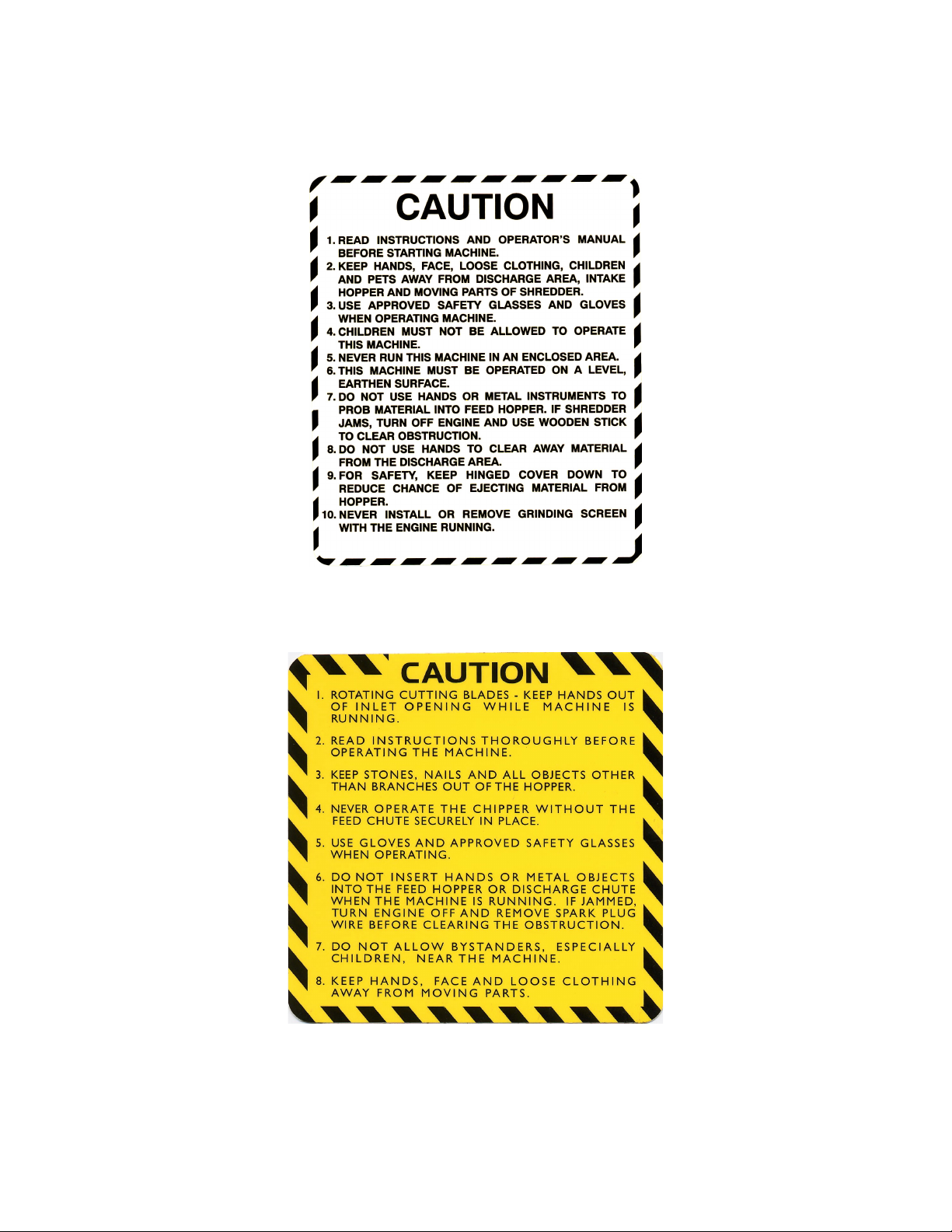
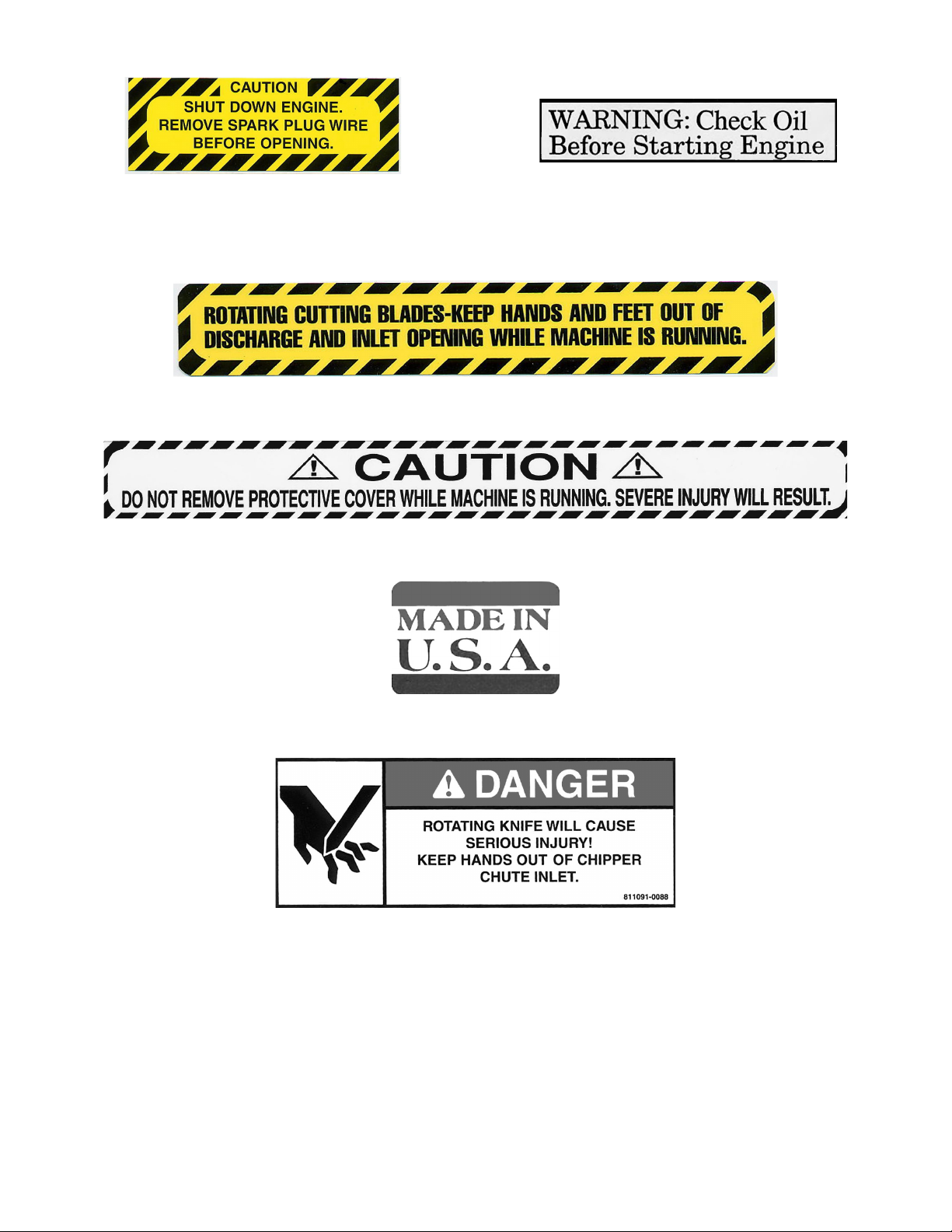
MAKE CERTAIN THAT ALL SAFETY LABELS ON THIS EQUIPMENT ARE
KEPT CLEAN AND IN GOOD CONDITION. IF YOU NEED REPLACEMENT
LABELS, ORDER BY PART NUMBER.
080-0962
080-0967
3
Page 4
080-0970
091-0055
091-0059
091-0043
091-0062
091-0088
4
Page 5
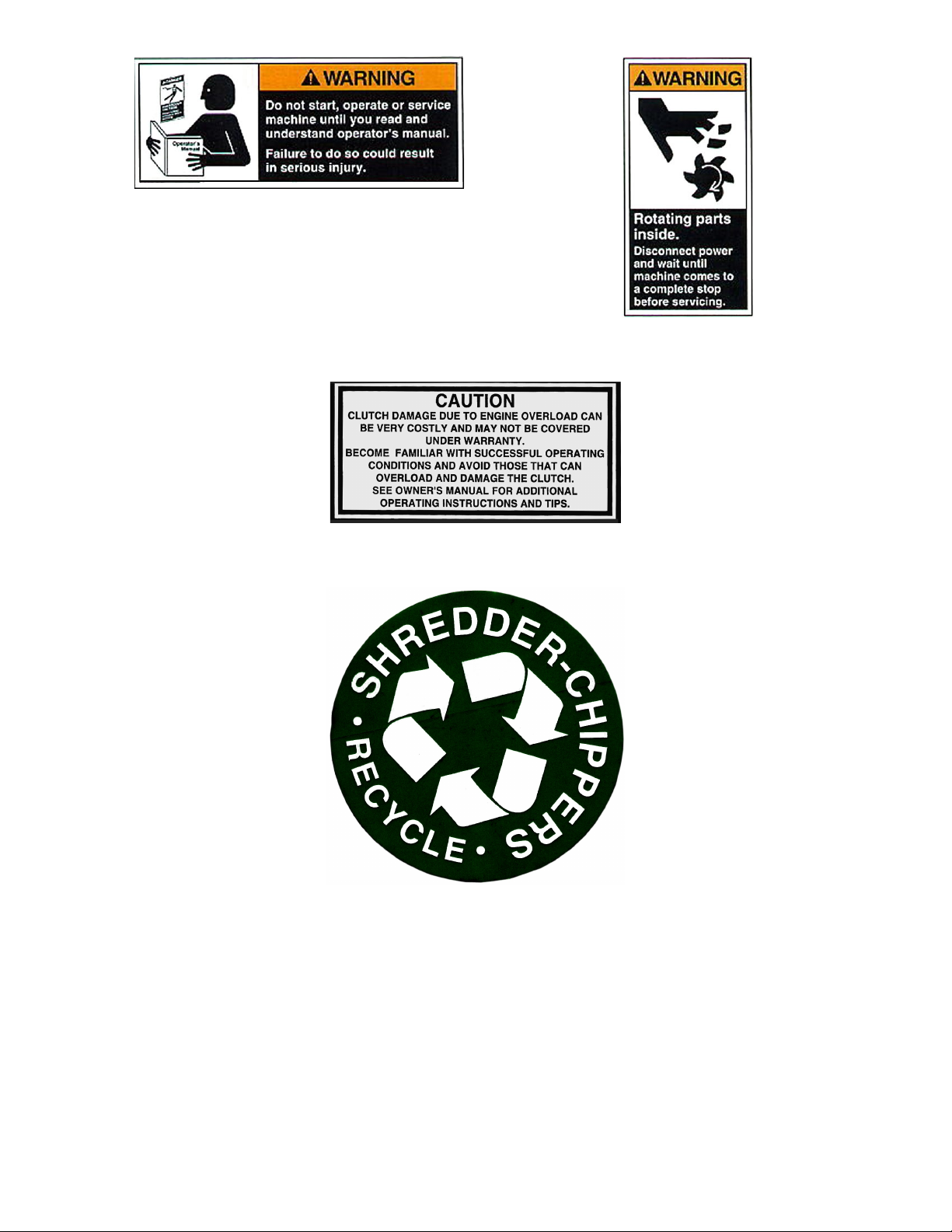
091-0380
091-0381
913-0265
091-0044
5
Page 6

SAFE OPERATION PRACTICES
TRAINING
Read this owner’s manual carefully in its entirety before attempting to assemble this machine. Read,
understand, and follow all instructions on the machine before operation. Be completely familiar with the
controls and the proper use of the machine before operating it. Keep this manual in a safe place for future and
regular reference and for ordering replacement parts.
Know how to stop the unit and disengage the controls quickly.
Never allow children to operate the unit. Never allow adults to operate the equipment without proper
instruction. Only responsible individuals who are familiar with these rules of safe operation should be allowed
to use your unit.
Keep the area of operation clear of all persons, particularly small children and pets. Stop the engine when they
are in the vicinity of the unit. Keep work area clean and clear of branches or obstacles, which could cause you
to stumble or fall.
Keep in mind that the operator or user is responsible for accidents or hazards occurring to other people, their
property, and themselves.
Your shredder/chipper is a powerful tool, not a plaything. Exercise extreme caution at all times. Your unit has
been designed to shred and chip. Do not use it for any other purpose.
If situations occur which are not covered in this manual, use care and good judgment. Contact your place of
purchase for additional assistance.
PREPARATION
Thoroughly inspect the area where the equipment is to be used and remove all foreign objects.
Do not operate the machine without wearing adequate outer garments and safety goggles. Always wear safety
glasses or goggles during operation and while performing any adjustment or repair, to protect eyes from foreign
objects that may be thrown from the machine. Be sure your glasses or goggles fit properly.
Avoid loose-fitting clothes and use protective footwear that will improve footing on slippery surfaces. Shirt and
slacks that cover the arms and legs and steel-toed shoes are recommended. Secure hair above shoulders. Do
not wear loose clothes or jewelry that can be caught in moving parts. Never operate a unit in bare feet, sandals
or sneakers. Wear gloves when feeding material into the shredder hopper or chipper chute. Be sure your
gloves fit properly and do not have loose cuffs or drawstring.
Warning: Fuel is highly flammable and the vapors are explosive. Take the following precautions.
Store fuel and oil in approved containers.
Keep away from heat and open flame, and out of the reach of children.
Refuel outdoors only and do not smoke while refueling.
Check and add fuel before starting the engine. Never remove gas cap or add fuel while the engine is
running or when the engine is hot. Allow engine to cool before refueling.
If fuel is spilled, do not attempt to start the engine but move the machine away from the area of spillage and
avoid creating any source of ignition until fuel vapors have disappeared.
Replace all fuel tank and container caps securely.
Never store the machine or fuel container inside where there is an open flame or spark, such as a gas hot
water heater, space heater, clothes dryer or furnace.
To reduce fire hazard, keep engine and muffler free of debris build-up. Clean up fuel and oil spillage.
Allow unit to cool at least five minutes before storing.
Never attempt to make any adjustments while the engine is running.
6
Page 7

OPERATION
Never place your hands, feet, or any part of your body in the shredder hopper, chipper chute, discharge
opening, or near or under any moving part while the shredder/chipper is running. Keep clear of the discharge
opening at all times. If it becomes necessary to push material into the shredder hopper or chipper chute, use a
small diameter stick, NOT YOUR HANDS.
Keep your face and body back from the shredder hopper and chipper chute to avoid accidental bounce back of
any material.
The machine should only be operated on a level surface. Never operate your unit on a slippery, wet, muddy, or
icy surface.
Exercise caution to avoid slipping or falling.
Stay alert for hidden hazards or traffic. Do not carry passengers.
If the cutting mechanism strikes a foreign object or if your machine should start making an unusual noise or
vibration, immediately stop the engine, remove the spark plug wire(s) and wait for all moving parts to come to a
complete stop. After the machine has come to a complete stop proceed as follows:
Inspect for any damage.
Repair or replace any damaged parts before restarting and operating the machine.
If the machine should start to vibrate abnormally, immediately stop the engine, remove the spark plug wire(s)
and wait for all moving parts to come to a complete stop and inspect for the cause. Vibration is generally a
warning sign of trouble.
Stop the engine when leaving the operating position, and when making any repairs, adjustments and
inspections.
Take all possible precautions as recommended by the manufacturer when leaving the machine unattended.
Stop the engine and remove the key if so equipped.
Before cleaning, repairing, or inspecting, shut off the engine and make certain the flywheel and all moving parts
have come to a complete stop. Disconnect the spark plug wire and keep the wire away from spark plug to
prevent accidental starting. Do not use flammable solutions to clean air filter.
Never run this machine in an enclosed area as the exhaust from the engine contains carbon monoxide, which
is an odorless, tasteless, and deadly poisonous gas.
Keep all guards and safety devices in place and operating properly. Do not operate the machine if all safety
guards are not in place.
Do not use the unit with the shredder hopper or chipper hopper removed.
The muffler and engine become hot and can cause a severe burn. Do not touch.
Keep children and pets away.
Tragic accidents can occur if the operator is not alert to the presence of small children.
Keep children out of the work area and under the watchful eye of a responsible adult
other than the operator.
Be alert and turn the unit off if a child enters the area.
Never allow children to operate the shredder/chipper.
Do not overload or attempt to shred or chip material beyond manufacturers recommendation. Personal injury
or damage to the machine could result.
Never operate the machine at high transport speeds or on hard or slippery surfaces.
Never allow bystanders near the unit while running.
Only use accessories approved for this machine by the manufacturer. Read, understand, and follow all the
instructions provided with the approved accessory.
Only operate unit in good daylight. Do not operate unit at night or in dark areas where your vision may be
impaired.
Use extreme caution when reversing or pulling the machine towards you.
Do not tamper with the engine’s governor setting. The governor controls the maximum safe operation speed
and protects the engine. Over-speeding the engine is dangerous and will cause damage to the engine and to
the other moving parts of the machine. See your authorized dealer for engine governor adjustments.
Start the engine according to the manufacturer’s instructions. Keep hands and feet away from inlet and
discharge areas.
Never pick up or carry the machine while the engine is running.
Do not operate while under the use of alcohol, drugs, or medication. A clear mind is essential for safety.
Do not allow anyone who is not alert to operate this machine.
When feeding material into this equipment, be extremely careful that pieces of metal, rocks, or other foreign
objects are not included. Personal injury or damage to the machine could result.
7
Page 8

Keep area of discharge clear of people, animals, buildings, glass or anything else that will obstruct clear
discharge, cause injury or damage. Wind can also change discharge direction, so be aware.
Do not allow an accumulation of processed material to build up in the discharge area as this will prevent proper
discharge and can result in kickback from the shredder hopper or chipper chute.
Do not allow any part of the engine, especially around the cooling fans and muffler, to become clogged with
processed material, leaves, oil, grease or any other combustible material.
Do not operate engine if air cleaner or cover over carburetor air-intake is removed, except for adjustment.
Removal of such parts could create a fire hazard.
TOWING – HIGHWAY TOWABLE MODEL
Obey all state and local regulations when towing on public roads and highways.
Before towing, be certain the shredder chipper is correctly and securely attached to the towing vehicle and the
safety chains are in place. Leave slack in the chains to allow for turning.
Do not allow anyone to sit or ride on the shredder/chipper. This can cause serious injury.
Stay alert for hidden hazards or traffic. Do not carry passengers.
Never carry any cargo or wood on your shredder/chipper. It may fall off and endanger following vehicles.
Allow for added length when turning, parking, and crossing intersections and in all driving situations.
Be care when backing up, you. You can easily jackknife your shredder/chipper.
Adjust towing speed for terrain and conditions. Do not exceed 45 MPH when towing.
Because there is no suspension on the shredder/chipper, it will tend to bounce more on rough roads. Be extra
cautious when towing over bumpy or rough terrain including railroad crossings.
MAINTENANCE AND STORAGE
Keep machine, attachments and accessories in safe working condition.
Check engine mounting bolts and other hardware at frequent intervals for proper tightness. Never operate your
shredder/chipper in poor mechanical condition or when in need of repair. Be sure all safety guards and shields
are in proper position. These safety devices are for your protection.
Never store machine with fuel in the fuel tank inside a building where ignition sources are present, such as hot
water and space heaters, clothes dryers and the like. Allow the engine to cool before storing in any enclosure.
Always refer to the operator’s manual for important details if the machine is to be stored for an extended period.
If the fuel tank is to be drained, do this outdoors.
Follow the manufacturer’s recommendations for safe loading, unloading and storage of machine.
If it is necessary for any reason to unclog the feed intake or discharge openings or to inspect or repair the
machine where a moving part can come in contact with your body or clothing, shut the machine off, allow all
moving parts to come to a complete stop and disconnect spark plug wire(s) before attempting to unclog, inspect
or repair.
Check the knife mounting screws at frequent intervals for proper tightness. Also visually inspect the knife for
wear or damage. Replace the knife with parts that meet original equipment specifications.
Knives should be checked for sharpness and the bolts attaching them to the flywheel for tightness every 8-10
hours of operation.
Check the gap between the knife and wear plate every time you sharpen or replace the knife, or every 8-10
hours of operation.
Never tamper with safety devices. Check their proper operation regularly.
Inspect the belt each time you use the unit. Look for damage, worn areas or tears. Do not use the unit if this
condition exists.
Do not tamper with the engine’s governor setting. The governor controls the maximum safe operation speed
and protects the engine. Over-speeding the engine is dangerous and will cause damage to the engine and to
the other moving parts of the machine. See your authorized dealer for engine governor adjustment
8
Page 9
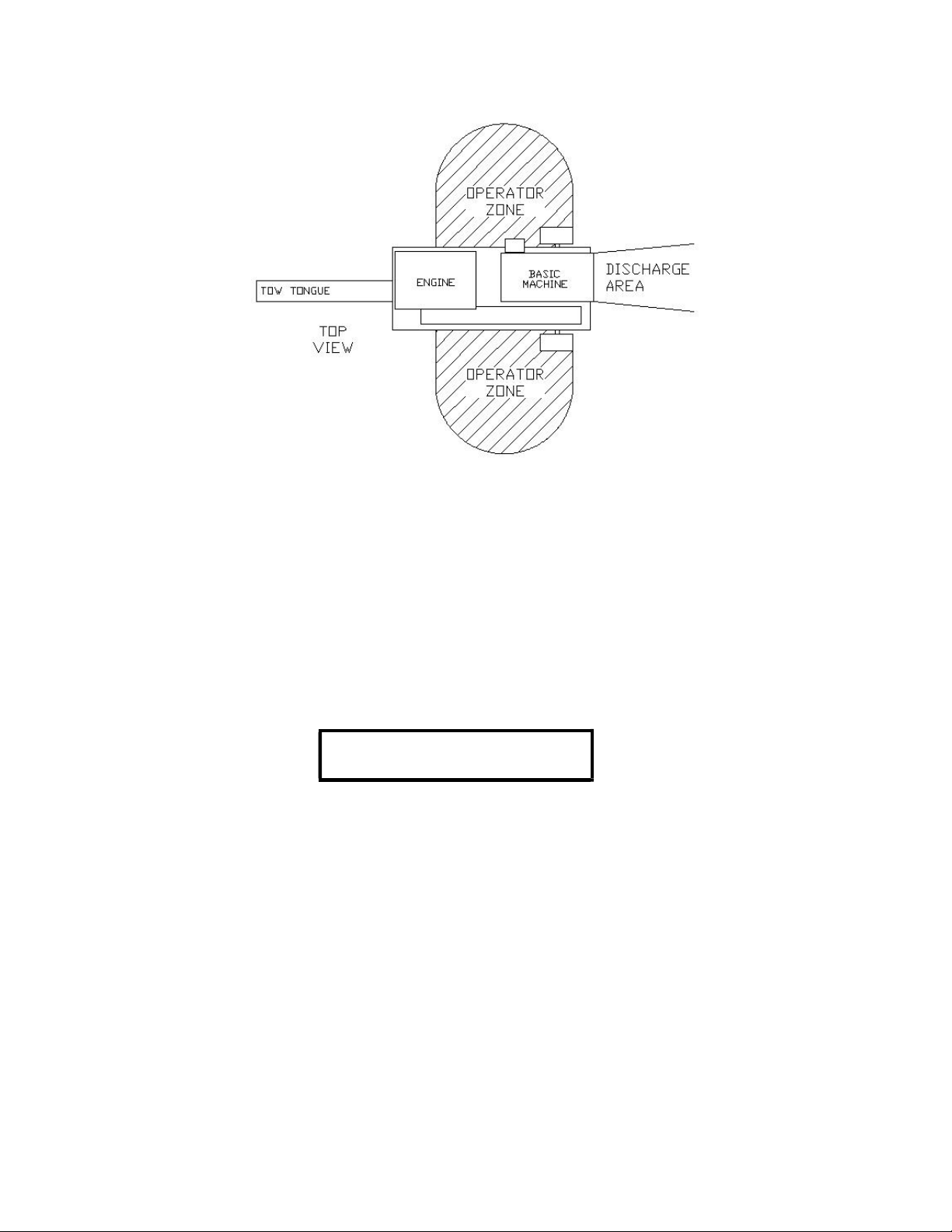
OPERATOR ZONE
Only operate your shredder/chipper from the operator zone.
Know how to turn your unit off.
Never move your shredder/chipper or leave it unattended with the engine running.
Follow engine owner’s manual for engine maintenance and repair.
YOUR RESPONSIBILITY
Restrict the use of this power machine to persons who read, understand,
and follow the warnings and instructions in this manual and on the machine.
SAVE THESE INSTRUCTION
FOR FUTURE REFERENCE
A NOTE TO ALL USERS:
Under California law, and the laws of some other states, you are not permitted to operate an internal combustion
engine using hydrocarbon fuels without an engine spark arrester. This also applies to operation on US Forest
Lands. In the state of California and Washington the above is required by law. Other states may have similar laws.
A spark arrester for the muffler is available through the engine manufacturer’s servicing dealer. Failure of the
owner/operator to maintain this equipment in compliance with state regulations is a misdemeanor under California
law and may be in violation of the other state and/or federal regulations. Contact your local fire marshal or forest
service for specific information in your area.
ADDITIONAL INFORMATION AND POTENTIAL CHANGES
MacKissic, Inc. reserves the right to discontinue, change, and improve its products at any time without notice or
obligation to the purchaser. The descriptions and specifications contained in this manual were in effect at printing.
Equipment described within this manual may be optional. Some illustrations may not be applicable to your
machine.
9
Page 10
SKID PARTS BOX
BOLTBAG
PART #
WHERE USED
BASIC MACHINE
HITCH PLATE
4 EA –
5/16-18 X ¾” CARRIAGE BOLT
090-0462 4 EA –
CHIPPER HOPPER
CHIPPER HOPPER
STAND
9 EA –
5/16 FLATWASHERS
090-0233 4 EA –
CHIPPER HOPPER
SHREDDER HOPPER
OWNER'S MANUAL
4 EA –
SHREDDER HOPPER
TOW TOUNGE
ENGINE MANUAL
1 EA –
FRONT TOW TONGUE
PARTS BOX
WARRANTY CARD
11 EA
– 5/16-18 NYLOCK NUT
090-0460 4 EA –
CHIPPER HOPPER
BOLTBAG
4 EA –
SHREDDER HOPPER
KNIFE GAUGE
2 EA –
HITCH PLATE
1 FRONT TOW TONGUE
7 EA –
5/16-18 X 1” HHCS
090-0088 2 EA –
HITCH PLATE
1 EA –
FRONT TOW TONGUE
4 EA –
SHREDDER HOPPER
1 EA – ¼-
20 X 1 ¼” U
-
BOLT
090-0610 1 EA –
REAR TOW TONGUE
2 EA – ¼-
20 NYLOCK NUT
090-0470 2 EA –
REAR TOW TONGUE
1 EA –
1/8 HAIR COTTER PIN
706-0924 1 EA -
STAND
SECTION II - ASSEMBLY INSTRUCTIONS
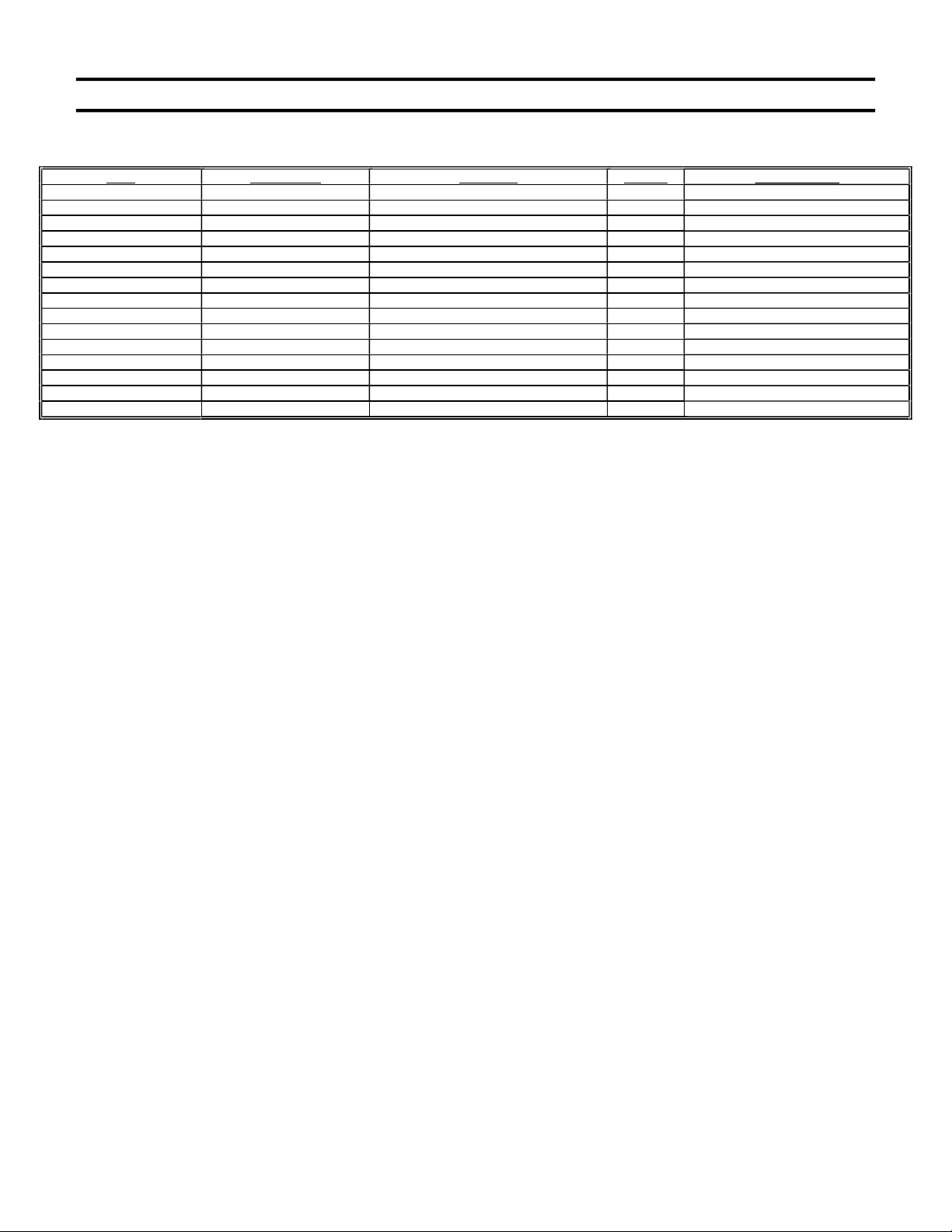
PACKAGE CONTENTS
10
Page 11
STEP I – UNPACKING AND CHECKING CONTENTS
1. Remove all items from the crate.
2. After unpacking the crate, compare the contents with the list above.
3. If any parts are missing, contact your place of purchase at once.
4. Assembly should be done on a clean, level surface.
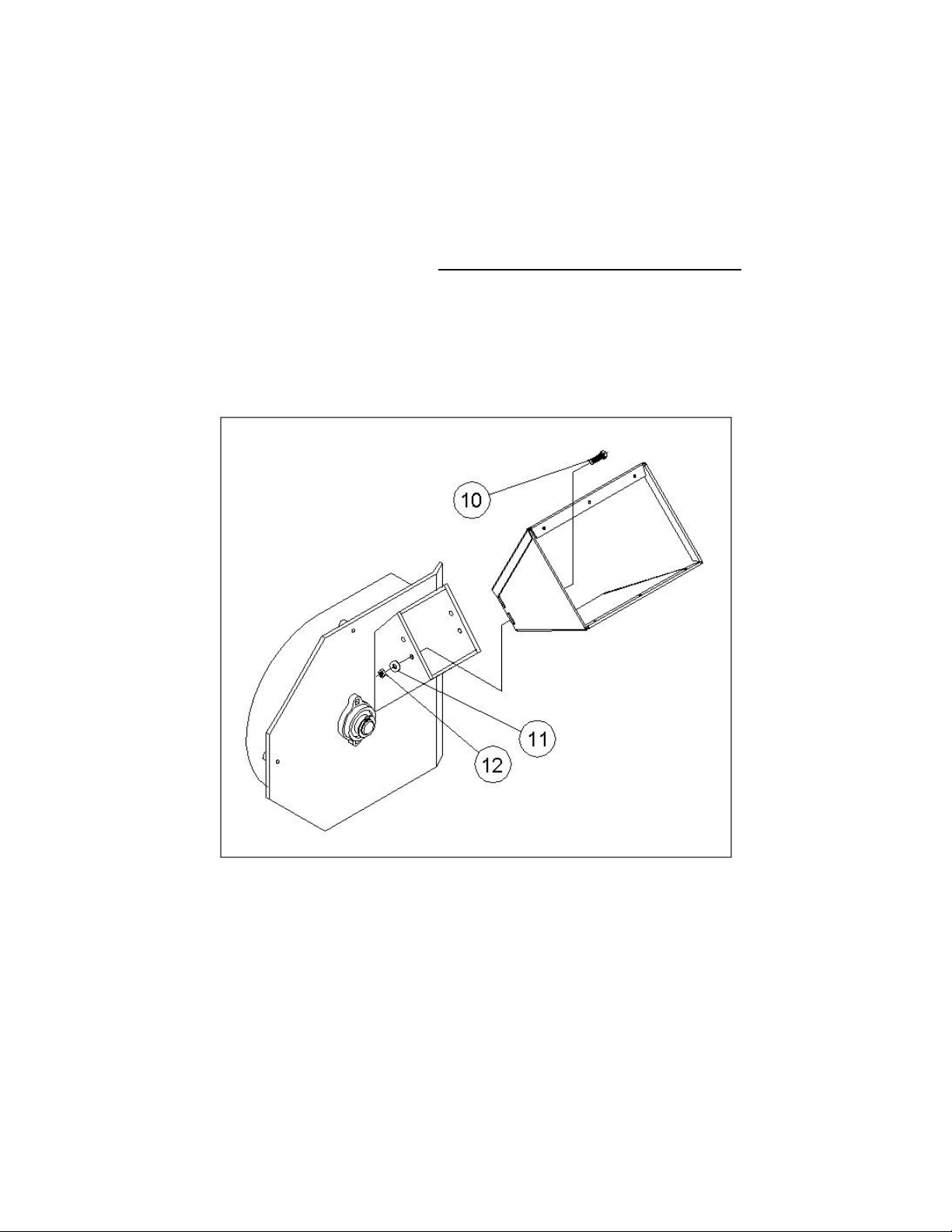
STEP II – INSTALLING THE CHIPPER HOPPER – HIGHWAY AND NON-HIGHWAY MODELS
1. Attach the chipper hopper to the basic machine with four 5/16-18 carriage bolts (#10), flat washers (#11) and
nylock nuts (#12). Put the bolts through the hopper from inside and secure with the flatwashers and the nylock
nuts. Secure tightly.
2. During attachment of the hopper to the machine, adjust the hopper up or down to achieve a smooth transition
between the hopper and the chute on the machine. If the hopper slips too low, branches can hit the chute,
preventing proper feeding.
11
Page 12
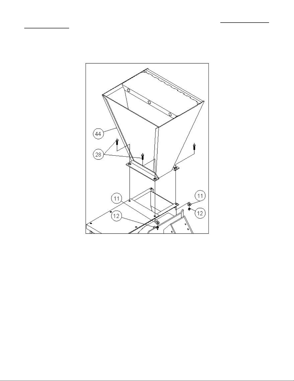
SECTION III – INSTALLING THE SHREDDER HOPPER - (If not installed from factory) – HIGHWAY AND NONHIGHWAY MODELS
1.Set shredder hopper (#44) in place on top of the basic machine. Secure in place with four 5/16-18 x 1” HHCS
(#39), four 5/16 flat washers (#11) and four 5/16-18 nylock nuts (#12).
12
Page 13
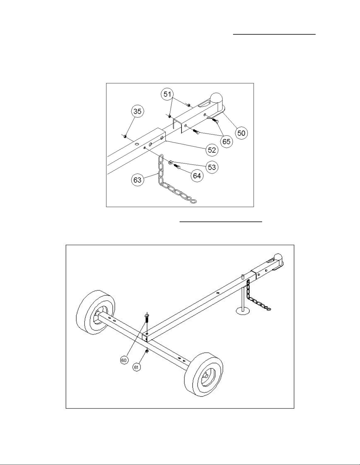
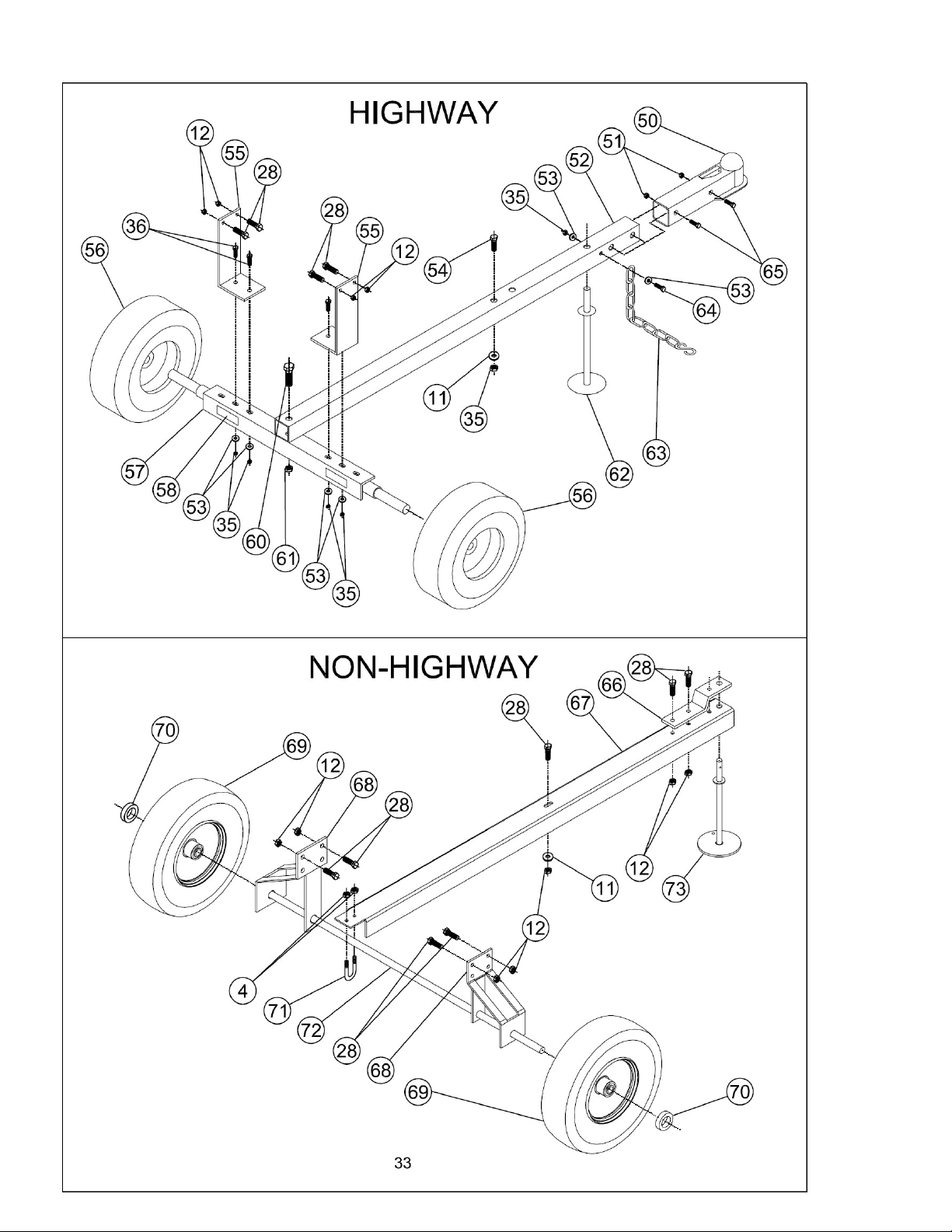
STEP V – ATTACHING HITCH AND SAFETY CHAINS TO TOW TONGUE – HIGHWAY TOWABLE MODEL
1. Slide the hitch (#50) over the end of the tow tongue (#52).
2. Secure the hitch to the tow tongue with two ½-13 x 3” HHCS (#65) and two ½-13 gripco locknuts (#51).
3. Take the 3/8-16 x 3 ½” HHCS (#64) and put a 3/8 washer (#53) and one of the safety chains (#63) on the bolt.
Put the bolt through the tow tongue, add the other safety chain to the bolt and secure with a 3/8 flat washer and
a 3/8-16 nylock nut (#35).
STEP VI – ATTACHING TOW TONGUE TO MACHINE - HIGHWAY TOWABLE MODEL
1. Put tow tongue in place on top of axle and secure with 5/8-11 x 3 ½” HHCS (#60) and 5/8-11 nylock nut (#61).
13
Page 14
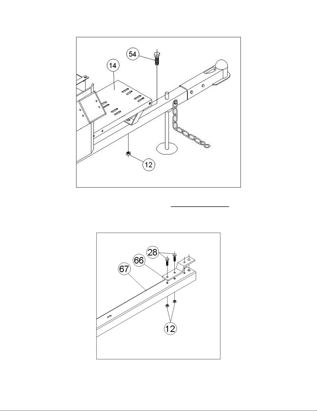
2. Attach the front of the tow tongue to the engine base weldment (#14) with a 5/16-18 x 3” HHCS (#54) and a
5/16-18 nylock nut (#12).
STEP VII – ATTACHING HITCH PLATE TO TOW TONGUE – NON-HIGHWAY MODEL
1. Attach the hitch plate (#66) to the tow tongue (#67) with two 5/16-18 x 1” HHCS (#28) and two 5/16-18 nylock
nuts (#12).
14
Page 15
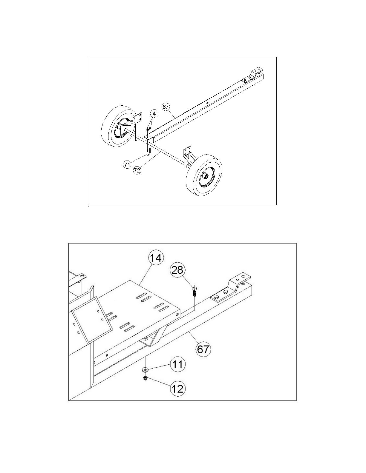
STEP VIII – ATTACHING TOW TONGUE TO MACHINE – NON-HIGHWAY MODEL
1. Set the tow tongue (#67) in place on top of the axle (#72) as shown.
2. Secure in place with the u-bolt (#71) and two ¼-20 nylock nuts (#4).
3. Attach the front of the engine base (#14) to the tow tongue (#67) with a 5/16-18 x 1” HHCS (#28), a 5/16 flat
washer (#11) and a 5/16-18 nylock nut (#12).
15
Page 16

SECTION III - LUBRICATION & ENGINE START UP
FOR INFORMATION ABOUT:
OIL
FUEL
STARTING
STOPPING
RECOMMENDED MAINTENANCE
SERVICE
STORAGE
ENGINE WARRANTY INFORMATION
REFER TO THE ENGINE OWNER’S MANUAL.
THE ENGINE ON YOUR CHIPPER SHREDDER HAS BEEN SHIPPED DRY.
BE SURE TO SERVICE THE ENGINE ACCORDING TO THE ENGINE
OWNER’S MANUAL PRIOR TO STARTING.
FAILURE TO DO SO CAN RESULT IN DAMAGE NOT WARRANTIED BY THE
ENGINE MANUFACTUROR.
WARNING: Do not fill closer than ½” from the top of the fuel tank to prevent spills and to allow for
fuel expansion. If gasoline is accidentally spilled, move the machine away from the area of the spill.
Avoid creating any source of ignition until gasoline vapors have disappeared.
CAUTION: Experience indicates that alcohol blended fuels (gasohol, ethanol, methanol) can attract moisture which
leads to separation and formation of acids during storage. Acidic gas can damage the fuel system or an entire
engine while in storage. To avoid engine problems, the fuel system should be empty before storage for periods
over 30 days. For more information, refer to the engine owner’s manual. Use fresh fuel each season. Never use
engine or carburetor cleaner products in the fuel tank or permanent damage may result.
ALWAYS CHECK OIL LEVEL PRIOR TO
STARTING THE CHIPPER SHREDDER.
16
Page 17

SECTION IV – SHREDDING & CHIPPING
THIS SHREDDER/CHIPPER WAS DESIGNED FOR SHREDDING LEAFY GARDEN OR
ORGANIC MATERIAL AND CHIPPING LIMBS OR BRANCHES. NEVER USE THIS
MACHINE FOR ANY OTHER PURPOSE AS IT COULD CAUSE SERIOUS INJURY.
CONTACT WITH INTERNAL ROTATING HAMMERS WILL CAUSE SERIOUS PERSONAL
INJURY. DO NOT PUT HANDS, FACE, FEET OR CLOTHING INTO THE SHREDDER
HOPPER, CHIPPER CHUTE, DISCHARGE OPENING OR NEAR THE DISCHARGE AREA AT
ANY TIME.
MAINTENANCE AND SERVICE SHOULD ONLY BE PERFORMED AFTER THE ENGINE IS
OFF AND ALL MOVING PARTS HAVE COME TO A COMPLETE STOP. USE ONLY A
WOODEN STICK TO CLEAR JAMMED MATERIAL AFTER ALL MOVING PARTS HAVE
STOPPED COMPLETELY.
SAFETY FIRST
Always wear protective gloves and safety glasses during operation of the
shredder/chipper.
Never allow your hands or any part of your body or clothing inside the feed hoppers or
discharge area of the shredder/chipper.
Keep all protective guards and warning labels on the machine and in good working
condition.
Always stand clear of the discharge area when the shredder/chipper is running.
Keep your face and body back from the feed hoppers to avoid being struck by any
material that may bounce back.
Keep proper balance and footing while operating the shredder/chipper.
If it becomes necessary to push material into the feed hoppers, only use a wood stick,
never your hands or anything steel.
Never assume you know where the chipper knife is. You do not know where it is.
Keep area of discharge clear of people, animals, buildings, glass or anything else that will
obstruct clear discharge, cause injury or damage. Wind can also change discharge
direction, so be aware.
Always keep hands out of the feed hoppers.
Never operate the shredder/chipper without the hoppers in place.
Do not transport the shredder/chipper with the engine running.
PROCESSING MATERIAL
Your shredder/chipper can process dry or green material.
Green material will process quicker and easier than dry material.
Soft wood processes easier the hard wood.
Your operator experience will teach you how different materials shred and chip.
Your operator experience will teach you how fast you can process different materials.
Most materials process well with the standard screen provided with the unit.
17
Page 18

When chipping branches, sometimes a tail will be left at the end of a branch. To avoid
this, rotate the branch as it is fed into the chute.
Rotating the branch as you feed it into the machine will improve chipping performance.
An optional screen is available for greater reduction of the material being processed
through the shredder hopper.
USING THE SHREDDER HOPPER
The shredder hopper is located on the top of the unit and is the opening into which all materials to be shredded
should be fed. Most organic materials can be shredded. A flex guard, or blowback shield is secured to the
hopper. Material must be pushed past this flap using a wooden stick in order to enter the main shredding
chamber where revolving steel hammers do the shredding. The blowback shield is an important feature. It
prevents kickback of materials! Do not use your machine unless the blowback shield is securely
fastened in place.
Due to the wide variety of materials that can be shredded, and their very different physical characteristics, only
feed limited quantities of any material into the hopper at first. The amount and length of material can be
increased if you find that the material is being processed without any difficulty. Your judgment and operator
experience are very important. Be sure not to overload the machine by feeding too much material into the
hopper at one time. If you hear the RPM’s of the engine decreasing, stop feeding material into the machine at
once. Do not resume feeding the machine until it has returned to full speed.
The maximum diameter of material that can be shredded is 1”. Any larger material should be fed through the
chipper-hopper. Material larger than 1” can cause serious damage to any of the internal parts of the shredding
chamber. The unit should be inspected after every use for bent hammers, missing spacers, damage to the
screen or any other obvious problems. If damage occurs, the rotor assembly can become unbalanced causing
excessive vibration. If used in this state, damage can occur. Do not use the machine if vibration is present.
Vibration is generally a warning sign of trouble.
Several small branches can be fed into the shredder-hopper at once providing their combined diameter is less
than 1”. Branches longer than three feet should be cut to make them more manageable. Green materials
should be allowed to dry, or processed in small batches with dry materials to avoid winding around the rotor
assembly.
Wet materials will clog the machine easily. For best results, allow wet materials to dry for 7 to 10 days before
processing. If clogging occurs, you can remove the screen and process material without, but the reduction will
not be as great. Slowing your rate of feeding material into the machine will also reduce the chance of clogging.
MATERIALS BEST SUITED FOR SHREDDING
Leaves
Roots
Grass clippings
Straw
Hay
Small branches
Flowers
Soil
Garden debris
Hedge clippings
Kitchen Waste
Manure
Corn Stalks
Palm frond tops
Potato vines
Tomato vines
Paper
NOTE - The hammers within the shredding chamber can tug suddenly at material being
fed into the shredder-hopper. Do not hold on tightly to branches and vines, and don’t
feed material straight down into the hopper with your arm pointing downward toward
the opening. Instead, keep your arms parallel to the ground and several inches above
the top edge of the hopper.
18
Page 19

USING THE CHIPPER HOPPER
This chipper-hopper is mounted on the side of the machine and is designed to chip the larger, heavier materials that
the shredder-hopper isn’t designed to handle. Branches fed into the chute are turned into “chips” by the revolving
chipper knife mounted on a flywheel. The chipper-hopper can chip branches and vines ranging in size from 1” to 4”
in diameter. Cut your materials into manageable lengths before feeding them into the chipper.
Note: The chipper hopper must be securely bolted to the side of your equipment before using the machine!
Do not force material into the chipper. If the machine does not chip well, the chipper knives need replaced or
sharpened or the gap between the knife and the wear plate needs adjusting.
Extremely hard knots will not process very well. Short stubs that have not self-fed through the chipper can be
pushed through with the next branch to be chipped. DO NOT THROW REMAINING STUBS OR UNCHIPPABLE
KNOTS INTO THE SHREDDER-HOPPER. DAMAGE WILL RESULT.
Cut chipping material into manageable lengths of no more than five or six feet long before chipping them.
If branches are larger than 1” in diameter, feed only one branch at a time through the chipper hopper.
Branches smaller than 1” in diameter can be bundled together and fed through the chipper hopper at one time.
Overloading the shredder/chipper will cause the rotor speed to decrease. If you hear the RPM’s decreasing, stop
feeding material into the machine until the machine has returned to full speed.
MATERIALS BEST SUITED FOR CHIPPING.
Branches, vines or stalks from 1” to 4” in diameter.
USE COMMON SENSE WHEN USING YOUR SHREDDER/CHIPPER.
LEARN TO RECOGNIZE THE CHANGE IN THE SOUND OF YOUR MACHINE WHEN IT IS
OVERLOADED.
BECOME FAMILIAR WITH SUCCESSFUL OPERATING CONDITIONS AND AVOID THOSE THAT
CAN OVERLOAD AND DAMAGE THE MACHINE.
IF THE MACHINE BECOMES JAMMED BY OVERLOADING OR ANY OTHER CAUSE, STOP THE MACHINE
IMMEDIATELY.
IF YOU JAM THE MACHINE AND DO NOT STOP THE ENGINE, IT CAN DAMAGE THE MACHINE. THIS
DAMAGE CAN BE COSTLY AND IT MAY NOT BE COVERED UNDER WARRANTY. FOR THIS REASON, IT
IS IMPORTANT THAT YOU IMMEDIATELY STOP THE ENGINE IF THE MACHINE BECOMES JAMMED.
ONLY YOUR OPERATOR EXPERIENCE WILL TELL YOU HOW FAST TO FEED MATERIAL TO BE
PROCESSED.
CHECK TO SEE THAT THE FLYWHEEL WILL TURN FREELY BEFORE YOU START THE
SHREDDER/CHIPPER.
VISUALLY CHECK CHIPPER KNIFE FOR DAMAGE EACH TIME YOU USE YOUR SHREDDER/CHIPPER.
CHECK KNIFE CONDITION, WEAR PLATE CONDITION, GAP SETTING AND THE NUTS AND BOLTS THAT
HOLD THE KNIFE IN PLACE FOR TIGHTNESS EVERY 8-10 HOURS OF OPERATION.
DO NOT ALLOW PROCESSED MATERIAL TO BUILD UP WITHIN 3” OF DISCHARGE CHUTE OPENING.
TURN THE MACHINE BEFORE MOVING THE SHREDDER/CHIPPER OR PILE AS NEEDED. FAILURE TO DO
THIS COULD RESULT IN UNNECESSARY JAMMING OF THE MACHINE.
TO MOVE PILE OF PROCESSED MATERIAL, TURN THE MACHINE OFF AND USE A SPADE, RAKE, OR
LONG HANDLE TOOL. NEVER USE YOUR HANDS OR FEET!
19
Page 20
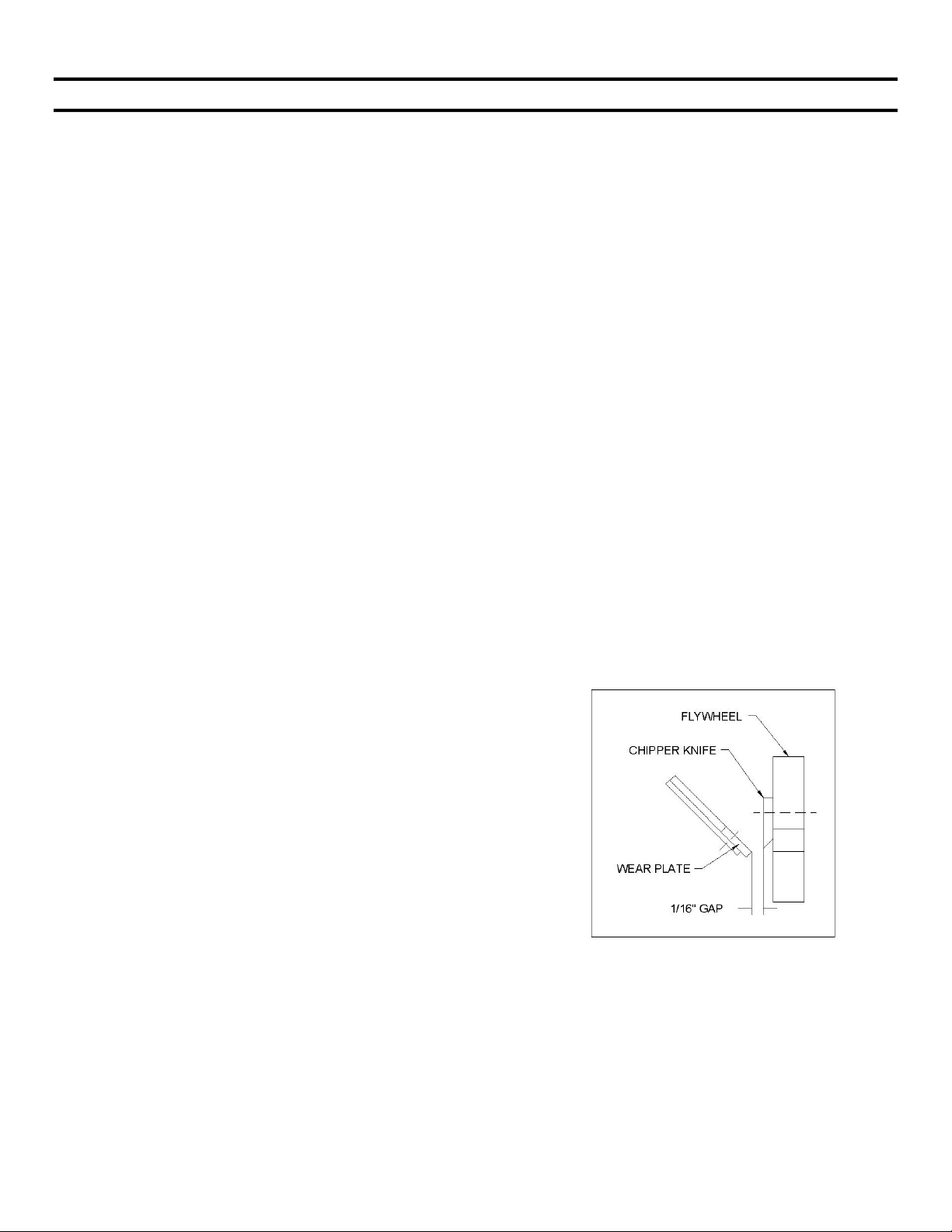
SECTION V – MAINTENANCE & STORAGE
IMPORTANT: The knife should be checked for sharpness and the bolts attaching them to the flywheel for
tightness every 8-10 hours of operation.
IMPORTANT: Every time you perform maintenance or any kind of service or check on the knife, be sure to check
the gap between the knife and wear plate for proper setting.
NOTE: A knife gauge has been provided with your machine. It is 1/16th” thick and should be used to set the
correct gap between the knife and wear plate.
If the cutting mechanism strikes any foreign object or if your machine should start making an unusual noise or is
vibrating, stop the engine, disconnect the spark plug wire(s) from the spark plug(s). Allow the engine to cool before
you:
a. Inspect and examine for damage.
b. Check for loose nuts, bolts or parts.
1. When not in use, your shredder/chipper should be stored out of the reach of children. Be sure that there are no
gasoline fumes in the storage area. For long periods of storage (over the winter), refer to the engine owner’s manual.
2. After every 8 hours of operation, lubricate the chipper side bearing. To do this, wipe all dirt, etc., from the grease
fittings with a clean cloth, then apply no more than 3 shots of quality general-purpose grease with a hand-pumped
grease gun. Over lubrication can also damage bearings. Also, check the bearing collar set screws regularly to be
sure they are tight. If they are loose, reset them with Loctite 243, obtainable at any hardware store.
3. You will find information included referring to operation and maintenance of the engine. Look it over carefully. BE
CERTAIN TO ADD OIL BEFORE STARTING IT.
4. When the steel chipping knife needs replacing or sharpening, refer to the section on removal, sharpening and reinstallation.
5. Care must be exercised when sharpening the knife to maintain the correct bevel and a straight edge. Refer to
sharpening directions. When you install a knife, the clearance between the knife and wear plate must be checked and
set. This clearance or gap should be set to 1/16” (see figure 1).
6. To adjust this clearance, loosen the three ¼” nuts and bolts
holding the wear plate in place. The wear plate can be slid up
or down (in or out) to achieve the correct gap setting.
7. Take the knife gauge and slide between the knife and wear
plate. If the gap is set correctly, the knife gauge will lightly
touch both the knife and wear plate. If the gap is too small, you
will not be able to get the gauge between the knife and wear
plate. If the gap is too large, there will be excess room between
the knife gauge, knife and wear plate. Tighten the nuts and
bolts when the wear plate is in the correct position. Be certain
the flywheel rotates without hitting anything before starting the
chipper.
8. If the gap between the wear plate and the knife is not set
correctly, you will have excessive vibration when chipping and
the blade will seem to be dull. This should be checked every 810 hours of operation.
9. If at any time it becomes necessary to disassemble the chipper
for repairs, the chipper disk must be re-installed in exactly the
same position on the rotor shaft.
c. Repair or replace any damaged parts before restarting and operating the machine.
NOTE: Proper gap setting is critical to the proper operation of your machine.
20
Page 21
REMOVAL, SHARPENING AND RE-INSTALLATION OF CHIPPER KNIFE
HOW TO REMOVE THE KNIFE
Stop the engine.
Remove spark plug wire(s) and keep away from spark plug(s).
Disconnect battery at negative terminal.
Open the access cover on the chipper basic machine.
Rotate the chipper disk until the three countersunk screws attaching the knife to the flywheel are visible through
the access door.
Clean out the heads of the allen screws with an awl or sharp tool.
Insert a 3/16” allen wrench into the heads of the screws.
While applying pressure with the allen wrench, apply heat from a propane torch to the screws to break loose the
Loctite on the screws.
Remove the heat once the screws have loosened.
Remove all three allen screws in this manner.
KNIFE SHARPENING
You should never attempt to sharpen the chipper knife freehand.
It is extremely important that the 45-degree angle be maintained consistently for proper performance.
The chipper knife should be taken to a machine shop for proper sharpening.
Excessive heat generated during the sharpening process will damage knives and weaken the metal. Be sure the
knife is not overheated.
KNIFE INFORMATION
The chipper knife should be checked routinely for sharpness.
Using a dull knife will decrease performance and cause excessive vibration that will cause damage to the
shredder/chipper.
How many times a knife can be sharpened is determined by how much material needs to be taken off to sharpen
or to compensate for dents or gouges.
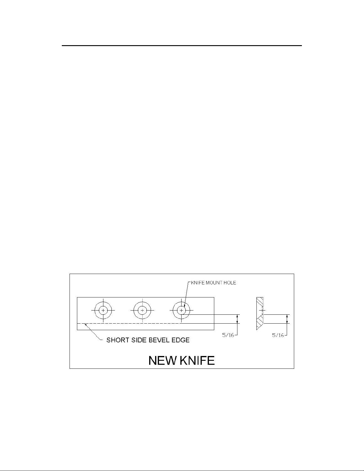
A new chipper knife has 5/16” measurement between the short side bevel edge and the knife mounting holes.
See figure 2.
Figure 2
21
Page 22
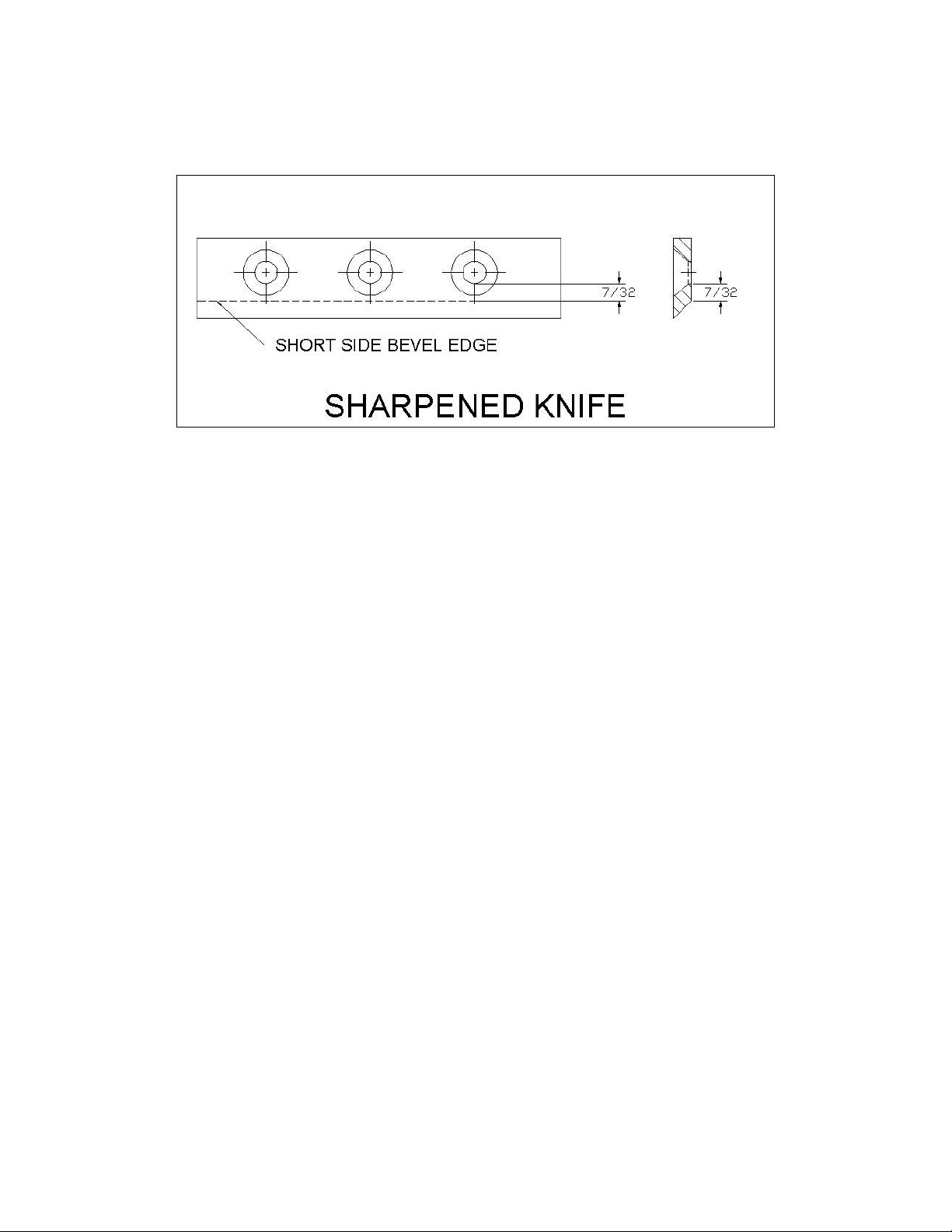
The knife should never be sharpened to the extent that more than 3/32” is taken off this measurement.
Once this measurement is below 7/32” (see figure 3) the knife should be replaced.
If you are unable to remove dents or gouges with these guidelines, replace the knife.
Figure 3
KNIFE INSTALLATION
Clean chipper disk where knife is going to be attached.
Visually inspect the chipper disk slot and knife mounting area and be sure they are clean and that the knife will be
able to mount flush against the chipper disk.
Visually inspect and clean the knife.
Apply Loctite 243 to the socket head cap screws that hold the knife in place.
Hand tighten the knife to the chipper disk. If you are installing a new knife, use the new hardware that comes with
the knife when attaching it to the chipper disk.
Tighten the center bolt.
Tighten the outer bolt.
Tighten the inner bolt.
Double-check all three for tightness one more time.
WEAR PLATE
The wear plate should have a square edge and be free of dents or gouges.
The wear plate can be sharpened by hand, but as with the knife, do not overheat during the sharpening process.
This will change the characteristics of the steel and it should be replaced.
Check the gap between the knife and wear plate every time any adjustments are done to either piece, or every 8-
10 hours of operation.
22
Page 23

AFTER ANY BLADE OR WEAR PLATE MAINTENANCE OR ADJUSTMENT, ROTATE THE
CHIPPER DISK BY HAND. WATCH AND LISTEN CAREFULLY FOR ANY UNUSUAL NOISES,
CLICKING OR VIBRATION. IF ANY OF THESE ARE DETECTED, INSPECT THE MACHINE FOR
DAMAGE. REPAIR OR REPLACE ANY DAMAGED PARTS AND CHECK FOR ANY LOOSE
PARTS AND RETIGHTEN.
KNIVES MUST BE CHECKED AND MAINTAINED!
THE KNIFE MUST BE SHARP!
BE SURE TO REINSTALL THE KNIFE CORRECTLY AND DOUBLE CHECK FOR
TIGHTNESS!
HAMMERS
When the hard steel hammers of the rotor assembly become dull or round on the cutting edge, they
may be rotated or reversed. These hammers have four cutting edges that may be used before
replacement is necessary. To reverse the hammers proceed as follows.
Remove belt guard.
Remove round cover plate from behind belt guard.
Remove the top plate.
Remove shredder hopper.
Turn rotor assembly until hammer rod is facing up.
Turn hammer rod until end of pin is facing up.
Drive the roll pin from the hammer rod with a punch.
Remove hammer rod through access hole on side of machine.
Reverse hammers and reinstall with spacers on hammer rod.
Replace old roll pin with new roll pin if necessary.
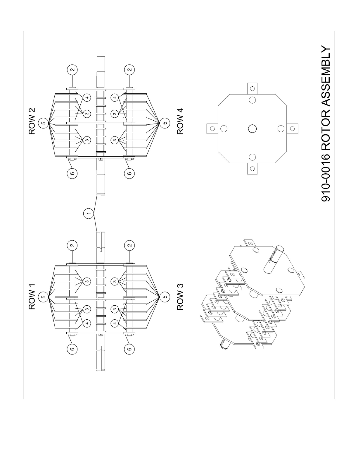
NOTE: Be sure the hammers and spacers are reinstalled in exactly the order in which they were removed. Refer
to the rotor assembly drawing for the correct order.
23
Page 24
INSTRUCTIONS FOR ADJUSTING OR REPLACING BELT
BELT ADJUSTMENT
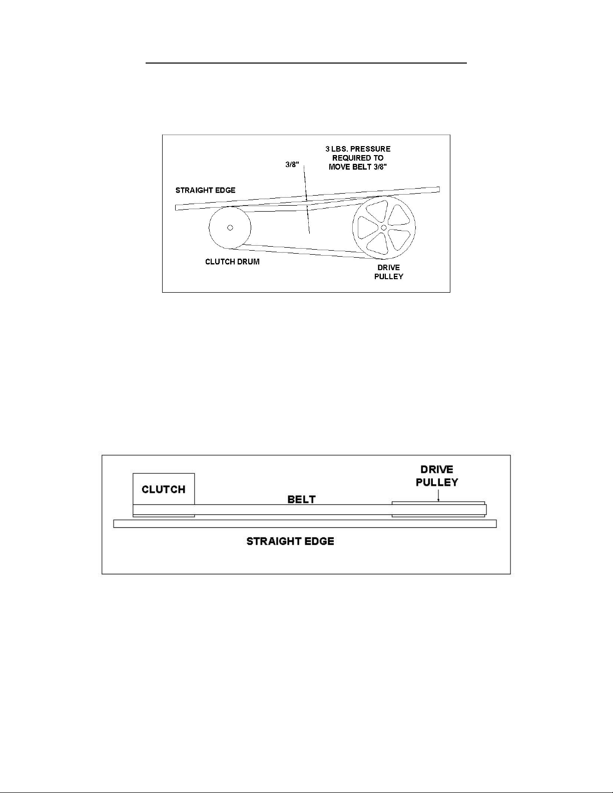
The belt on your chipper should deflect 3/8” under three pounds of pressure as shown in figure 1
below. If it doesn’t, adjust per the following directions.
Figure 1
Remove belt guard.
Loosen engine bolts.
Tighten or loosen the nut on the belt tensioner until you have the correct tension as shown in
figure 1.
Retighten engine bolts.
Check alignment of the clutch with the drive pulley by placing a straightedge across both faces
as shown in figure 2. If adjustment is necessary, correct alignment by moving rotor pulley in or
out on the rotor shaft. Do not make adjustment by moving the clutch on the engine shaft.
Replace belt guard.
Figure 2
BELT REPLACEMENT
To replace the belt, follow the above belt adjustment directions.
After you have loosened the engine bolts, remove the old belt and replace it with a new one.
Set belt tension and alignment per above directions.
NOTE: Check and re-tighten belts after initial break-in period, one hour of use.
24
Page 25

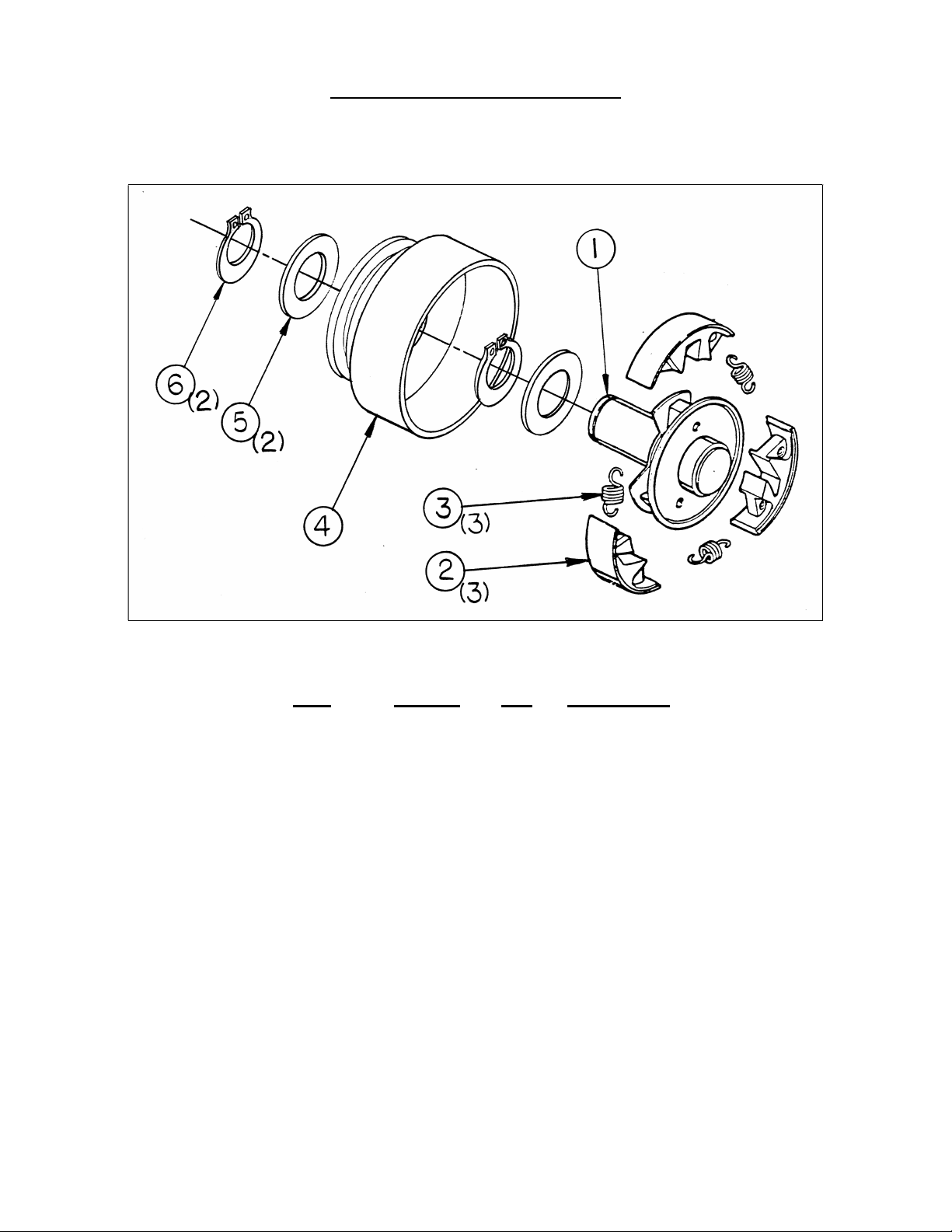
CENTRIFUGAL CLUTCH TECH TIPS
CLUTCH PART NO. 030-0202
THE SHOES AND SPRINGS ON THE CLUTCH ARE NORMAL WEAR ITEMS. IF YOU NOTICE
DECREASED PERFORMANCE OF THE CLUTCH THEY SHOULD BE CHECKED AND
REPLACED IF NECESSARY.
The clutch on your machine is designed for rugged, dependable service, however, it is
important to understand the limitations of a clutch. A clutch is designed to provide load free
starting of the engine, and slippage under excessive overloading of the driven application.
These features help protect the engine from damages such as broken crankshafts and
starters.
The clutch obtains its power from engine RPM’s. The lower the engagement speed, and the
higher the maintained engine speed, the more torque the clutch can transfer to the driven unit.
Do not operate at less than full RPM’s.
At engine start-up, the engine of your chipper operates under no load until approximately
1000-1200 RPM’S at which speed the centrifugal clutch engages and begins driving the rotor.
Proper rotor speed is 2400 RPM +/- 200 RPM.
Do not tamper with the engine’s governor setting. The governor controls the maximum safe
operation speed and protects the engine. Over-speeding the engine is dangerous and will
cause damage to the engine and to the other moving parts of the machine. See your
authorized dealer for engine governor adjustments.
Become familiar with successful operating conditions and avoid those that can
overload and damage the machine.
Do not overload or attempt to chip material beyond manufacturers recommendation. Personal
injury or damage to the machine could result.
Learn to recognize the sound of the machine when it is overloaded.
If the machine becomes jammed by overloading or any other cause, stop the machine
immediately.
If you jam the machine and do not stop the engine, it can:
Burn the belt.
Ruin the clutch.
Only your operator experience will tell you how fast you can successfully feed limbs into the
machine.
Clutch damage can be costly and it may not be covered under warranty. For this
reason, it is important that you immediately shut off the machine if it becomes jammed.
25
Page 26

CLUTCH MAINTENANCE
The centrifugal clutch on this machine is permanently lubricated and does not require oil or
grease. More lubricant can be added to the bushing. Any standard motor oil is recommended.
If, after long periods of use, the drum wobbles excessively, replace the drum assembly. Always
replace shoes and springs in sets. Whenever shoes are changed, replace all springs.
CLUTCH REMOVAL
1. Remove clutch from shaft by removing bolt and washers.
2. Slide clutch off shaft.
3. Remove key from keyway.
DISASSEMBLY OF EXISTING CLUTCH
1. Remove retainer ring and slide off drum assembly.
2. Unhook one spring from its shoe. Use tape wrapped pliers to avoid nicking spring.
3. Carefully note position of shoes. Remove shoes from hub.
REASSEMBLE
1. Locate shoes correctly on hub for rotation required.
2. Place one end of each spring over a shoe pin, stretch spring just enough to clear pin on the
other shoe. Use tape wrapped pliers to avoid nicking spring. Avoid over stretching that may
damage spring. Repeat for all shoes.
3. Replace washer on hub shaft.
4. Reassemble drum to hub, secure with retaining ring.
5. Locate key in keyway of hub.
6. Slide clutch onto crankshaft, then washers.
7. Secure hub by tightening cap screw and allen head set screws.
INSTALLATION OF A NEW CLUTCH
1. Clean shaft and remove any burrs.
2. Apply anti-seize compound to the shaft.
3. Place key in keyway on shaft.
4. Slide clutch onto shaft, secure with bolt, flat washer and lock washer.
5. Tighten two allen head set screws..
26
Page 27
030-0202
-6
1
Roller Bearing
030-0202 CLUTCH BREAKDOWN
Item Part No. Qty
1
2
3
4
6
---
Not Shown
030-0202-3
030-0164-2
030-0202-5
030-0202-2
030-0202-1
030-0164-6
Description
1
Hub Assembly
3
Shoe
3
Spring
1
Drum Assembly
1
Retaining Ring
2
Retaining Ring
27
Page 28

SYMPTOM
PROBLEM
CORRECTION
Check belt tension.
belt & tighten.
instructions.
incorrectly.
Clear chipper chamber.
TROUBLESHOOTING
Clutch overheats.
Belt burns.
Flywheel won’t turn.
Chipping action seems too
slow or flywheel stalling.
When chipping, log seems to
vibrate excessively &
“hammers” hands.
Chipper knife is hitting wear
plate.
Engine runs but flywheel
doesn’t rotate.
Clutch is slipping or flywheel is
jammed or stopped.
Engine speed is too slow.
Belts are slipping.
Knife is dull.
Gap between knife & wear
plate is too great.
The gap between the knife
and wear plate is set
Inner shoes of clutch worn.
Retaining springs weak or
broken.
Loose drive belt.
Immediately stop engine.
Remove spark plug wires.
Turn flywheel by hand to
be sure it turns freely.
Run engine at full throttle.
Check for loose or missing
Remove knife & sharpen -
be sure to maintain same
bevel of 45 degrees.
Adjust gap as per
Adjust gap per directions
in the front of this section.
Replace worn or broken
clutch parts.
Check belt tension.
28
Page 29

TIME
bolts for tightness.
Tighten if necessary.
purpose grease.
information.
Do not overfill.
replace spark plugs.
in engine manual.
LUBRICATION AND MAINTENANCE
OPERATION
PROCEDURE COMMENTS
BREAK IN
8 HOURS
40 HOURS
Change engine oil and
filter after first five
hours.
Check belt tension.
Check all nuts and
Check engine oil.
Check chipper knife
for sharpness.
Check knife and wear
plate gap.
Clean air filter.
Grease bearings on
basic chipper. *
Change engine oil. **
Check tire pressure.
Remove and sharpen
or replace chipper
knife.
Sharpen wear plate.
Follow oil
recommendations per
the engine & owner’s
manual.
Adjust per directions.
Per recommendations.
Do not overfill.
See knife information.
See gap setting
information.
Per engine
recommendations.
Use quality general-
Per recommendations.
Do not overfill.
Add or adjust as
required.
See knife information.
See wear plate
100 HOURS
Replace belt.
Change engine oil.
Order replacement
belts.
Per recommendations.
200 HOURS
Change engine oil
filter.
Clean and adjust, or
Per recommendations
in engine manual.
Per recommendations
* No more than three pumps of a hand-pumped grease gun. Do not over-grease as this may
damage the bearing seal.
** Lubrication schedule may vary depending on working environment. Overly dirty and dusty
situations will require more frequent oil changes to protect the engine.
29
Page 30
ITEM #
PART #
QTY
DESCRIPTION
SECTION VI - PARTS
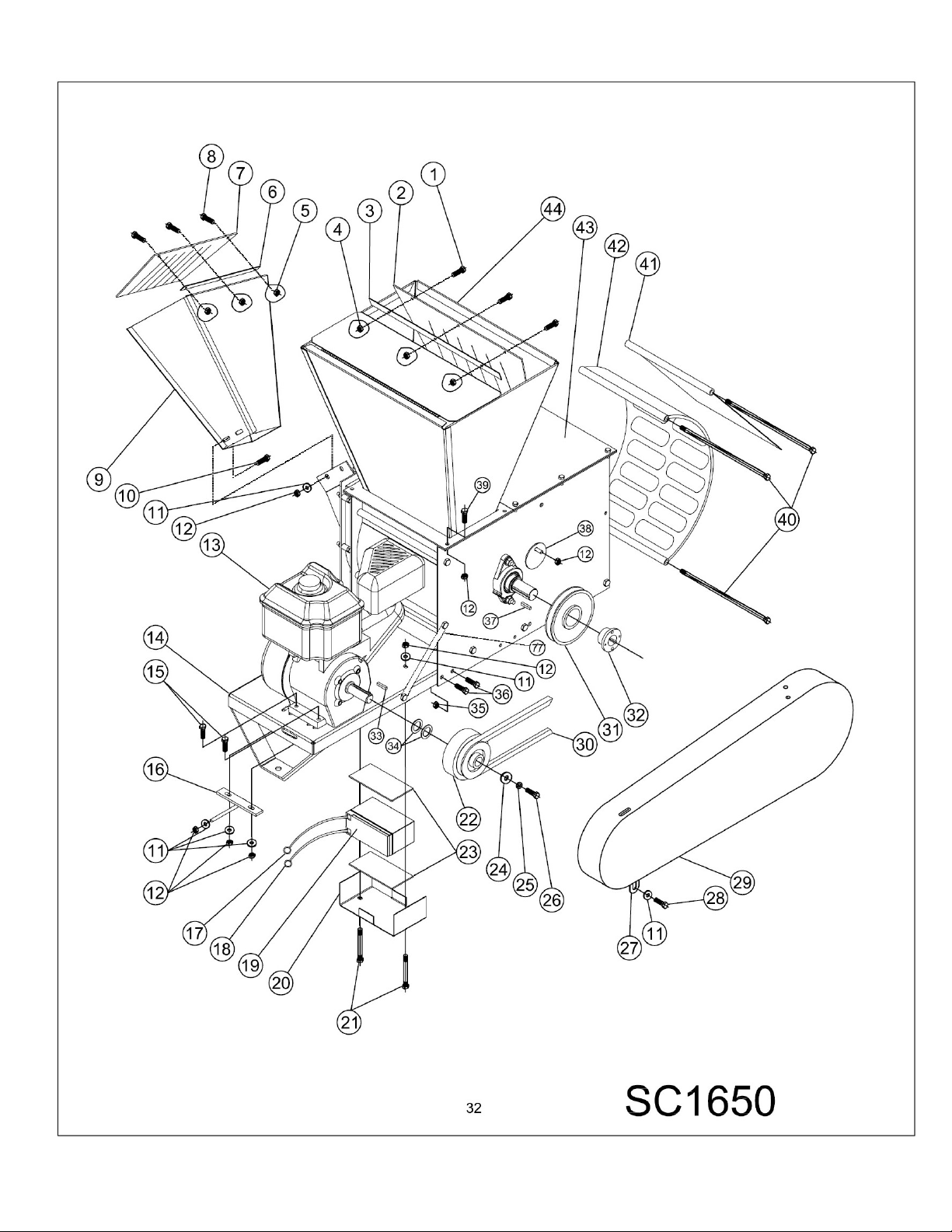
PARTS LIST
1 090-0012 3 ¼-20 X ¾” HHCS
2 910-0052 1 SHREDDER HOPPER BLOW BACK SHIELD
3 911-0049 1 BLOW BACK SHIELD MOUNT STRIP
4 090-0470 5 ¼-20 NYLOCK NUT
5 090-0703 3 10-24 NYLOCK NUT
6 913-0378 1 BLOW BACK SHIELD MOUNT STRIP
7 910-0053 1 CHIPPER HOPPER BLOW BACK SHIELD
8 090-0739 3 10-24 X ¾” HHMS
9 910-0039 1 CHIPPER HOPPER WELDMENT
10 090-0462 4 5/16-18 X ¾” CARRIAGE BOLT
11 090-0233 14 5/16 USS FLAT WASHER
12 090-0460 28 5/16-18 NYLOCK NUT
13 030-0602 1 1650 SERIES B&S ENGINE ELECTRIC START
14 910-0061 1 ENGINE BASE WELDMENT
15 090-0091 4 5/16-18 X 1 ¾” HHCS
16 913-0437 1 BELT TENSIONER
17 913-0097 1 POSITIVE BATTERY CABLE
18 913-0429 1 NEGATIVE BATTERY CABLE
19 030-0244 1 12V BATTERY
20 900-0332 1 BATTERY BOX
21 090-0076 2 5/16-18 X 3 ½” HHCS
22 030-0202 1 CLUTCH
23 030-0377 2 BATTERY PAD
24 704-0106 1 WASHER
25 090-0228 1 3/8 LOCK WASHER
26 090-0633 1 3/8-24 X 1 ½” HHCS
27 900-0103-1 3 BELT GUARD BRACKET
28 090-0088 18 5/16-18 X 1” HHCS
29 030-0484 1 BELT GUARD
30 030-0488 1 5H600 BELT
31 030-0443 1 6” SHEAVE
32 030-0444 1 QD BUSHING
33 703-0424 1 ¼ X 2” KEY
34 090-0024-3 3 SHIM
35 090-0461 10 3/8-16 NYLOCK NUT
36 090-0110 4 3/8-16 X 1” HHCS
37 080-0081 1 ¼ X 1 ¼” KEY
38 900-0040 1 COVER PLATE
40 910-0058 4 SCREEN & BAFFLE ROD
41 910-0051 1 BAFFLE WELDMENT
42 910-0048 1 SCREEN WELDMENT
43 910-0057 1 SC150 BASIC MACHINE
44 910-0024 1 SHREDDER HOPPER WELDMENT
50 913-0218 1 TRAILER HITCH
51 090-0050 2 ½-13 GRIPCO LOCKNUT
52 900-0252 1 TOW BEAM
53 090-0234 6 3/8 USS FLAT WASHER
30
Page 31
54 090-0093 1 5/16-18 X 3” HHCS
55 900-0249 2 AXLE BRACKET
56 702-0040 2 WHEEL & TIRE
57 911-0070 1 AXLE WELDMENT
58 030-0375 2 REFLECTOR
60 090-0201 1 5/8-11 X 3 ½” HHCS
61 090-0694 1 5/8-11 NYLOCK NUT
62 108-0076 1 STAND WELDMENT
63 408-0078 2 SAFETY CHAIN
64 090-0123 1 3/8-16 X 3 ½” HHCS
65 090-0370 2 ½-13 X 3” HHCS
66 913-0008 1 HITCH PLATE
67 913-0089 1 TOW BEAM
68 908-0060 2 AXLE BRACKET
69 030-0240 2 4.10/3.50 – 6 WHEEL & TIRE
70 090-0536 2 5/8” SHAFT COLLAR
71 090-0610 1 ¼-20 X 1 ¼” U BOLT
72 913-0090 1 28 ¼” AXLE
73 913-0029 1 STAND WELDMENT
74 080-0090 6 RIVET
75 090-0111 4 3/8-16 X 1 ¼” HHCS
76 500-0012 2 5/8” SPACER
77 911-0306 1 ENGINE BRACE
31
Page 32
32
Page 33
33
Page 34
ITEM #
PART #
QTY
DESCRIPTION
ITEM #
PART #
QTY
DESCR
IPTION
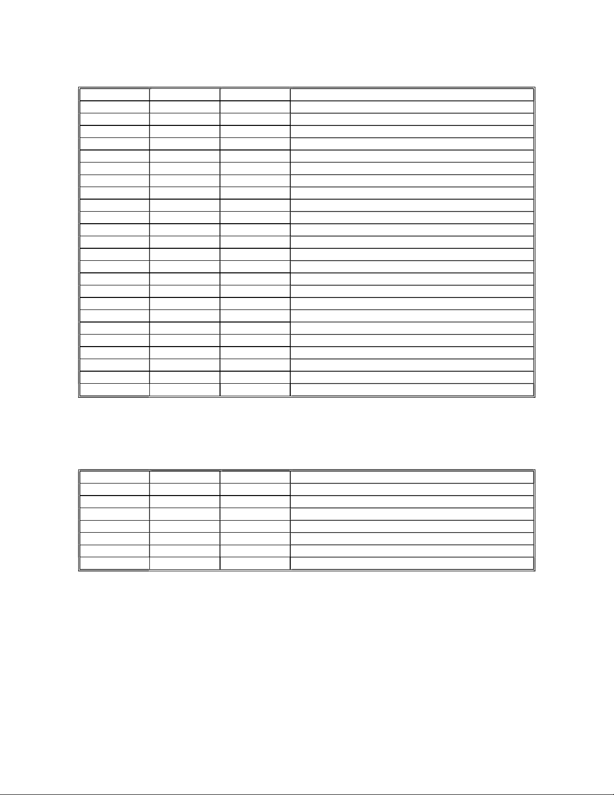
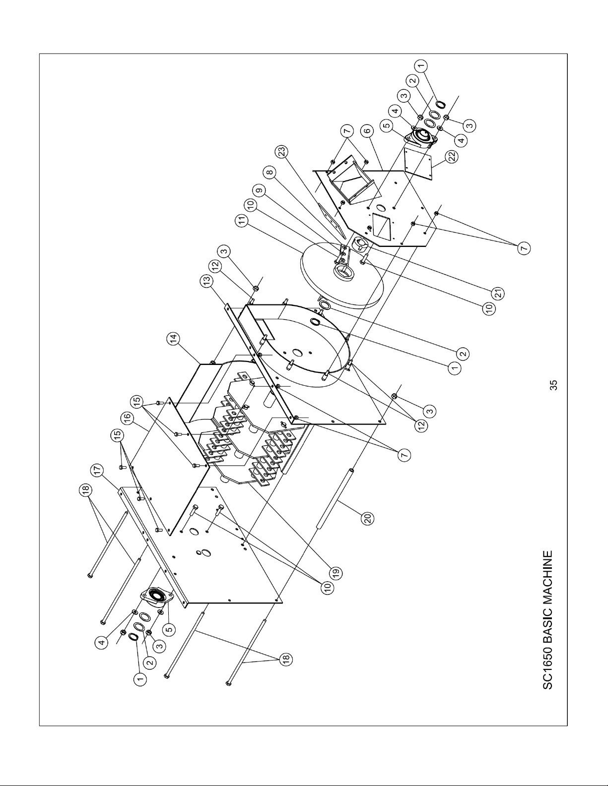
BASIC PARTS LIST
1 030-0449 3 RETAINING RING
2 030-0452 5 SHIM
3 090-0049 9 3/8-16 GRIPCO LOCKNUT
4 090-0233 4 5/16 USS FLAT WASHER
5 030-0441 2 BEARING
6 910-0022 1 CHIPPER CHUTE PLATE WELDMENT
7 090-0048 14 5/16-18 GRIPCO LOCKNUT
8 030-0498 1 KNIFE
9 090-0413 3 5/16-18 X 1” FHSHCS
10 090-0121 4 3/8-16 X 1 ¼” HHCS
11 910-0020 1 CHIPPER DISK – COMPLETE WITH KNIFE
12 090-0089 8 5/16-18 X 1 ¼” HHCS
13 910-0006 1 CHIPPER SIDE WELDMENT
14 910-0003 1 SCROLL WELDMENT
15 090-0066 6 5/16-18 X ¾” HHCS
16 910-0009 1 TOP PLATE
17 910-0056 1 DRIVE SIDE PLATE WELDMENT
18 910-0065 5 SCROLL BOLT WELDMENT
19 910-0016 1 ROTOR ASSEMBLY
20 910-0002 1 SCROLL TUBE
21 030-0442 1 TAPERLOCK BUSHING
22 913-0210 1 ACCESS COVER
23 910-0044 1 WEAR PLATE
ROTOR ASSEMBLY PARTS LIST
1 910-0012 1 ROTOR WELDMENT
2 910-0013 4 HAMMER ROD
3 910-0014 28 HAMMER SPACER
4 910-0015 8 HAMMER SPACER
5 500-0008 36 HAMMER
6 090-0626 4 ROLL PIN
34
Page 35
35
Page 36
36
Page 37

LIMITED WARRANTY
Any product manufactured by MacKissic, Inc. and found, in the judgment of MacKissic, Inc., to be defective in
material or workmanship, will be repaired or replaced by an Authorized MacKissic Service Dealer without charge for parts
and labor to the original owner of the MacKissic product.
The MacKissic product including any defective part must be returned to an Authorized MacKissic Service Dealer
within the warranty period. The expense of delivering the product to the dealer for warranty work and the expense of
returning it back to the owner after repair or replacement will be borne by the owner. MacKissic’s responsibility is limited
to making the required repairs or replacements only. No claim of breach of warranty shall be cause for cancellation or
rescission of the sales contract of any MacKissic product. Proof of purchase will be required by the dealer to substantiate
any warranty claim. All warranty work must be performed by an Authorized MacKissic Service Dealer.
This warranty is limited to two years from the date of original retail purchase for any MacKissic product that is
used for consumer purposes or 90 day for commercial and rental use.
This warranty does not cover any product that has been subject to misuse, abuse, neglect, negligence, or
accident, or that has been operated in any way contrary to or inconsistent with the operating instructions as specified in
the owner’s manual. The warranty does not apply to any damage to the product that is the result of improper
maintenance, or to any product or parts that have not been assembled or installed as specified in the owner’s manual.
The warranty does not cover any product that has been altered or modified. In addition, the warranty does not
extend to repairs made necessary by normal wear, or by the use of parts or accessories which, in the judgment of
MacKissic, Inc., are either incompatible with the MacKissic product or adversely affect its operation, performance or
durability. This warranty does not cover engines, electric starters, batteries, and tires which are warranted separately by
their manufacturer and for a different period of time.
MacKissic, Inc. reserves the right to change the design of any product without assuming any obligation to modify
any product previously manufactured.
THE DURATION OF THE LIMITED WARRANTY IS TWO YEARS CONSUMER, 90 DAYS COMMERCIAL AND
RENTAL USE. REPAIR OR REPLACEMENT AS PROCEEDED UNDER THIS LIMITED WARRANTY IS THE
EXCLUSIVE REMEDY OF THE PURCHASER. MacKissic, INC., SHALL NOT BE LIABLE FOR ANY INCIDENTAL OR
CONSEQUENTIAL DAMAGES, EXCEPT THE LIMITED WARRANTY DESCRIBED ABOVE, ALL IMPLIED
WARRANTIES (MERCHANTABILITY AND FITNESS FOR A PARTICULAR PURPOSE) ARE SPECIFICALLY
DISCLAIMED.
MacKissic, INC. ASSUMES NO RESPONSIBILITY FOR INCIDENTAL, CONSEQUENTIAL OR OTHER
DAMAGES INCLUDING, BUT NOT LIMITED TO, EXPENSE FOR GASOLINE, OIL, EXPENSE OF DELIVERING THE
PRODUCT TO AN AUTHORIZED MacKISSIC SERVICE DEALER AND EXPENSE OF RETURNING IT BACK TO THE
OWNER, MECHANIC’S TRAVEL TIME, TELEPHONE OR TELEGRAM CHARGES, RENTAL OF A LIKE PRODUCT
DURING THE TIME WARRANTY REPAIRS ARE BEING PERFORMED, TRAVEL, LOSS OR DAMAGE TO PERSONAL
PROPERTY, LOSS OF REVENUE, LOSS OF USE OF THE PRODUCT, LOSS OF TIME OR INCONVENIENCE.
This warranty gives you specific legal rights, and you may also have other rights that vary from state to state.
08/29/2022
37
Page 38
03/14/19
OWNER’S MANUAL REVISION FOR SC1650E/SC1650HTE
P/N 910-0055
PLEASE KEEP THIS SHEET WITH YOUR OWNER’S MANUAL AND REFERENCE IT
WHEN ORDERING PARTS AND/OR SAFETY DECALS
ITEM # PAGE DESCRIPTION NEW PART #
2 32 SHREDDER HOPPER BLOW BACK SHIELD 810-0298 & 910-0361
27 32 BELT GUARD BRACKET 921-0027-BL
29 32 BELT GUARD 940-3093-BL
44 32 SHREDDER HOPPER 910-0103-GR
13 35 CHIPPER SIDE PLATE (TD) 910-0102-GR
17 35 DRIVE SIDE PLATE 910-0101-GR
❑ NOT SHOWN
PART # DESCRIPTION QTY.
030-0640 BATTERY BOOTS 1
921-1097-BL INNER BELT GUARD 1
❑ NEW SAFETY DECALS
PART # DESCRIPTION QTY.
091-0057 DANGER, HANDS &FEET DECAL 2
913-0265 CLUTCH DAMAGE DECAL 1
930-0004 BELT GUARD WARNING DECAL 1
930-0006 AVOID ELECTRICAL SHOCK DECAL 1
930-0007 BURN HAZARD WARNING DECAL 1
930-0009 ROTATING PARTS WARNING DECAL 1
930-0010 DISCCHARGE WARNING DECAL 1
930-0013 DANGER, LARGE HOPPER DECAL 3
940-0001 ROTATING KNIFE WARNING DECAL 1
940-0011 DISCHARGE DANGER DECAL 1
 Loading...