

Migatronic SIGMA SELECT ROBO User Manual

BRUGSVEJLEDNING
USER GUIDE
BETRIEBSANLEITUNG
GUIDE DE L’UTILISATEUR
BRUKSANVISNING
GUIDA PER L’UTILIZZATORE
GEBRUIKERSHANDLEIDING
NÁVOD K OBSLUZE
PODRĘCZNIK UŻYTKOWNIKA
SIGMA SELECT ROBO
50115056 A Valid from 2018 week 37

2
Dansk ..................................................................3
English ..............................................................17
Deutsch ............................................................. 31
Français ............................................................. 45
Svenska ............................................................. 59
Italiano .............................................................73
Nederlands .......................................................87
Česky ............................................................... 101
Polski ...............................................................115
3
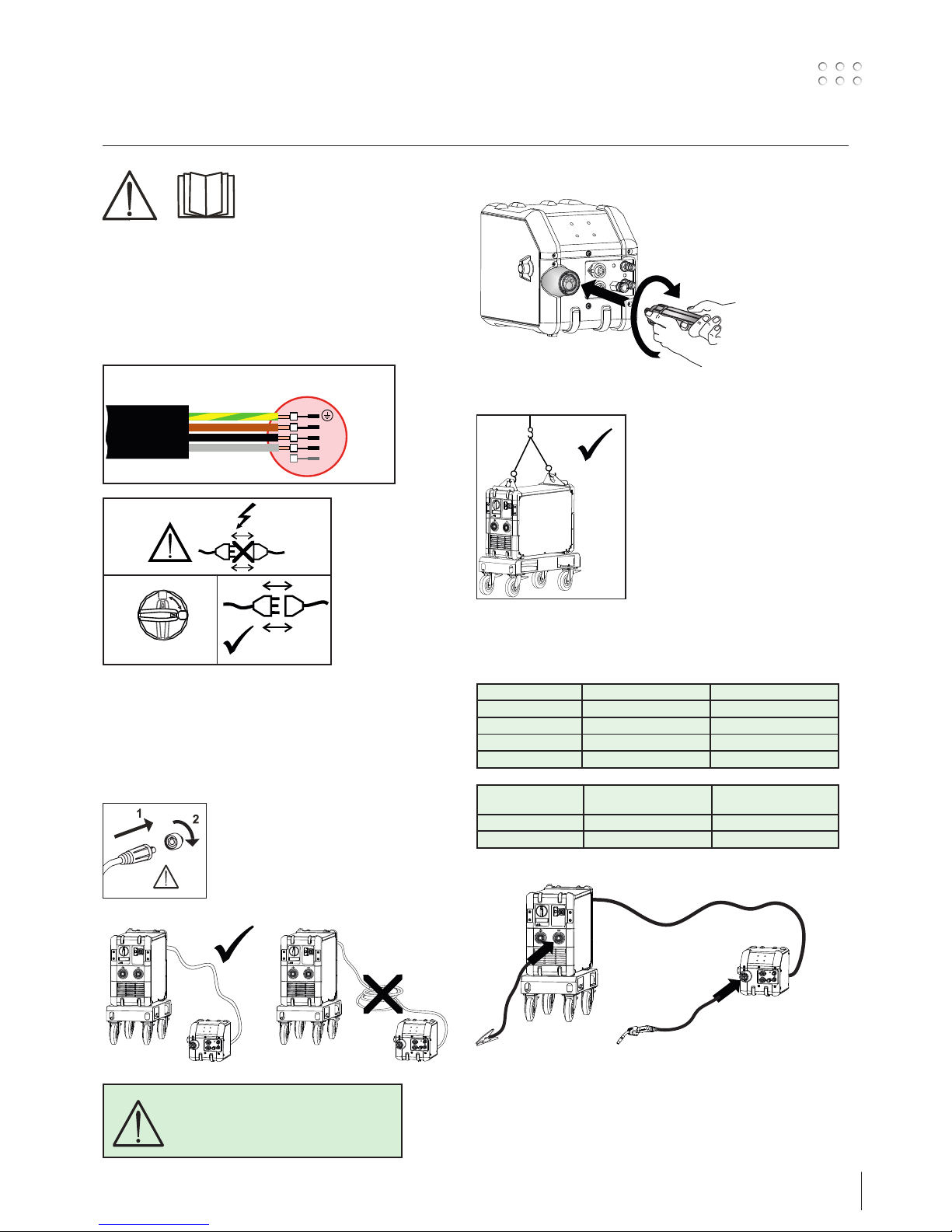
Tilslutning og ibrugtagning
1
0
1
Advarsel
Læs advarsel og brugsanvisning
omhyggeligt igennem inden
installation og ibrugtagning og gem
til senere brug.
Installation
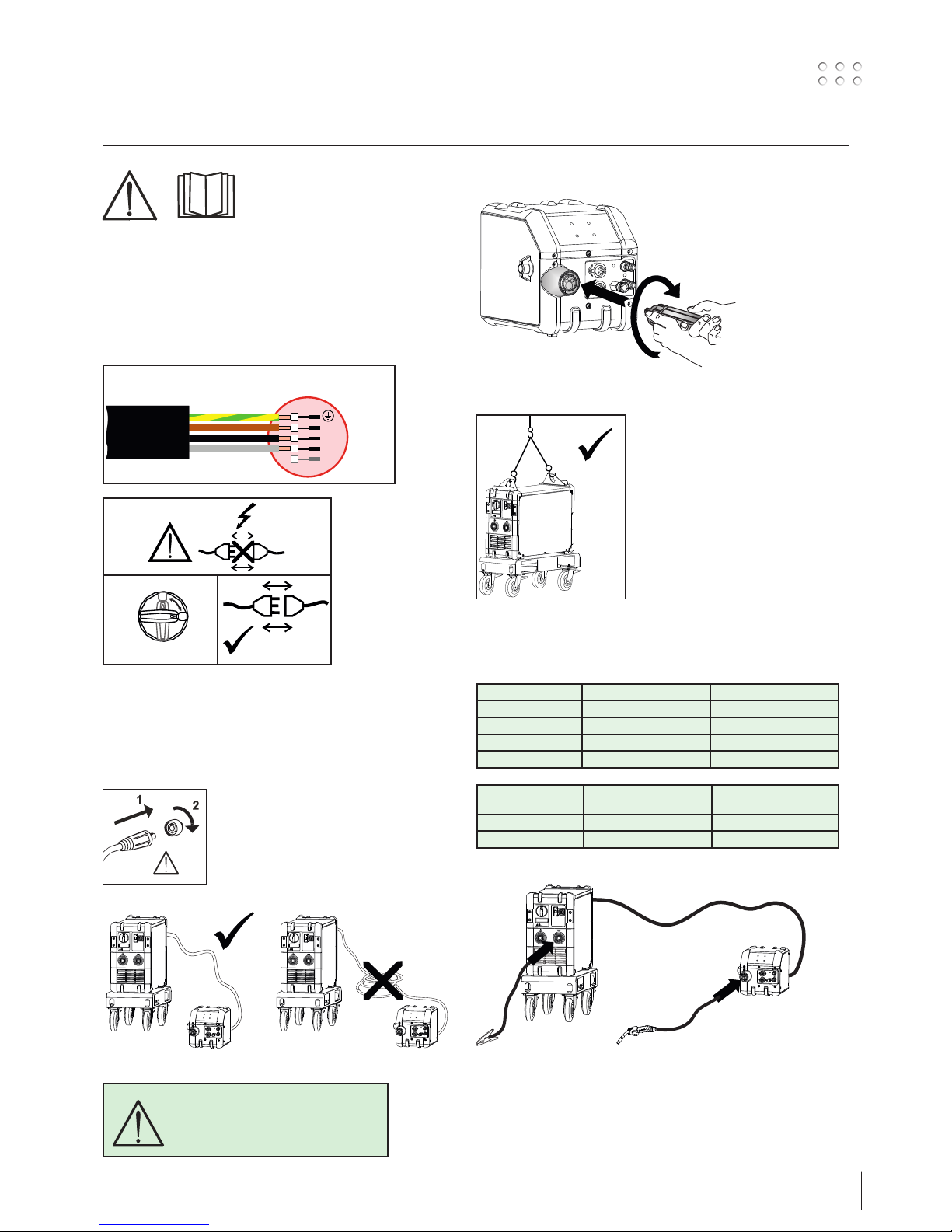
Nettilslutning
Tilslut maskinen til den netspænding den er konstrueret til. Se
typeskiltet (U1) bag på maskinen.
2
Tilslutning af beskyttelsesgas
Gasslangen, som udgår fra bagsiden af maskinen (3), tilsluttes
en gasforsyning med en reduktionsventil (2-6bar).
(Obs. Nogle typer reduktionsventiler kan kræve højere
udgangstryk end 2 bar for at fungere optimalt).
Vigtigt!
Når stelkabel og svejseslange tilsluttes
maskinen, er god elektrisk kontakt
nødvendig, for at undgå at stik og kabler
ødelægges.
ADVARSEL
Når der trykkes på svejseslangens
kontakt/tast er der spænding på
svejsetråden/elektroden.
Tilslutning af svejseslange
Løfteanvisning
(Løftekit varenr.: 78857054)
Anbefalede kabelstørrelser
Svejsestrøm DC PULS
200 A 35 mm² 35 mm²
300 A 50 mm² 70 mm²
400 A 95 mm² / 2x50 mm² 95 mm² / 2x50 mm²
550 A 2x70 mm² 2x70 mm²
Svejseproces Afstand til arbejdsemne
(a+b)
Total kabellængde i
svejsekredsløb (a+b+c)
MIG - IAC og puls 10 m 20 m
MIG - ingen puls 30 m 60 m
c
a
b
L1
L2
L3
N
gul/grøn
brun
sort
grå
3x208-440V (boost)
3x400V
4
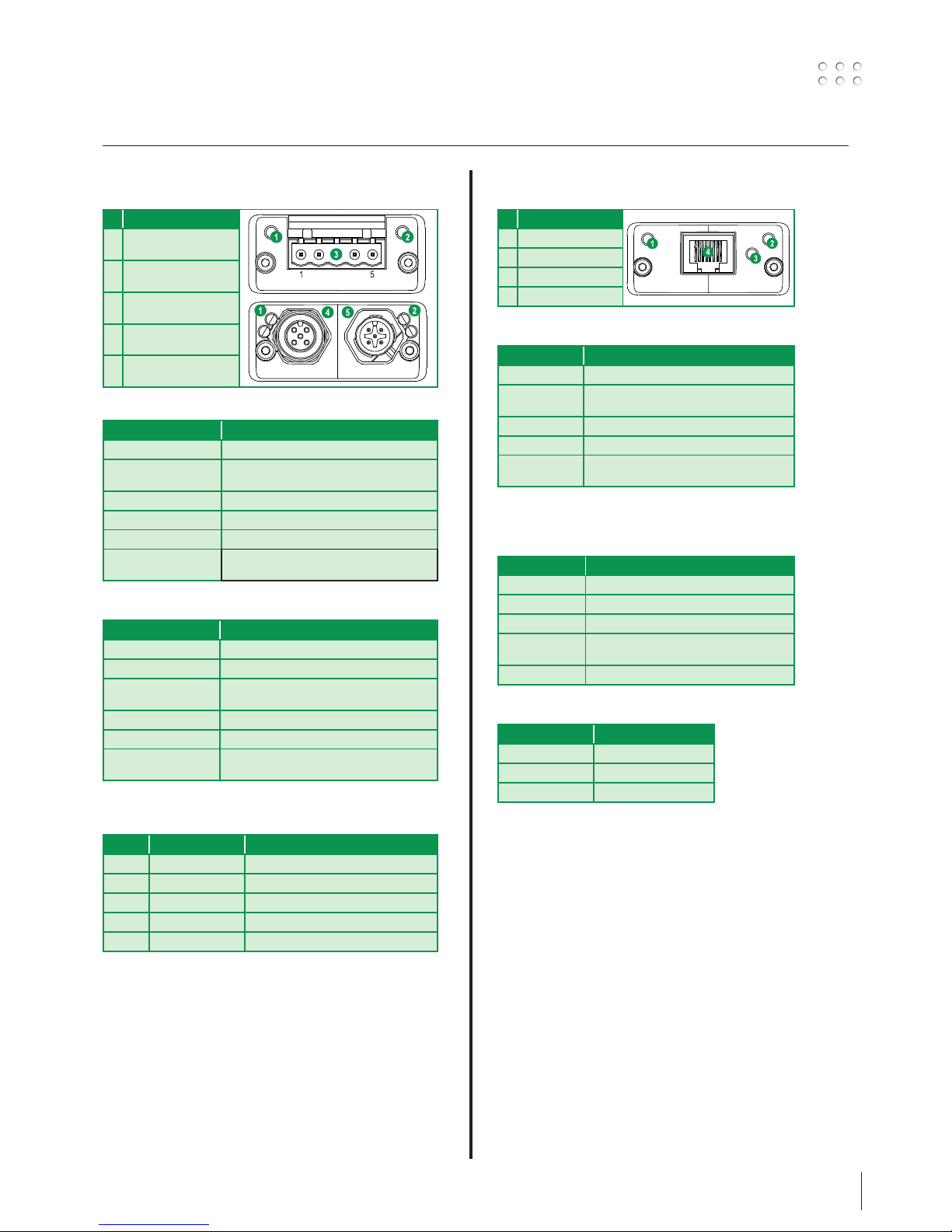
Tilslutning og ibrugtagning
11
GAS
2-6 bar
Power
F
F
F
1
2
3
4a
4b
5
5
6
6
7
7
8
9
10
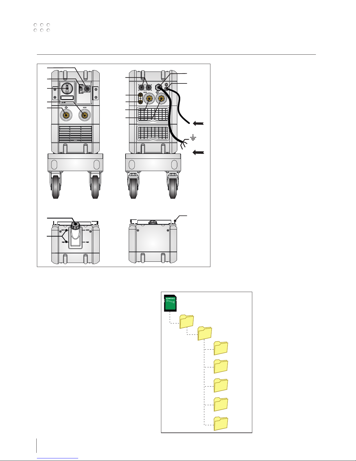
1. Nettilslutning
2. Tænd - sluk knap on/off
3. Tilslutning beskyttelsesgas
4a. Tilslutning køleslange, tilbageløb (rød)
4b. Tilslutning køleslange, fremløb (blå)
5. Dinsetilslutning -
6. Dinsetilslutning +
7. Tilslutning CAN
8. Fieldbusmodul
9. Påfyldning af kølevæske
10. Aflæsning af kølevæskestand (Min/Max)
11. Samlebeslag
MIGA_CFG
DOCUMENTS
Devicenet
EtherCAT
Profibus
Profinet
Ethernet-IP
Config.
Robot-/PLC-opstilling
SIGMA SELECT leveres med Migatronics standard
konfigurationsfil (10010208).
Det medfølgende SD-kort indeholder yderligere
konfigurationsfiler samt diverse opstillingsfiler, der er
påkrævet af nogle robotter og PLC’er.
Indlæs MIGA_CFG/DOCUMENTS folderne på din PC. Hver
folder indeholder EDS- eller GSD-filer, brugsanvisninger,
quickguides og diverse Anybus moduldokumentation til
kommunikationsenheder.
5
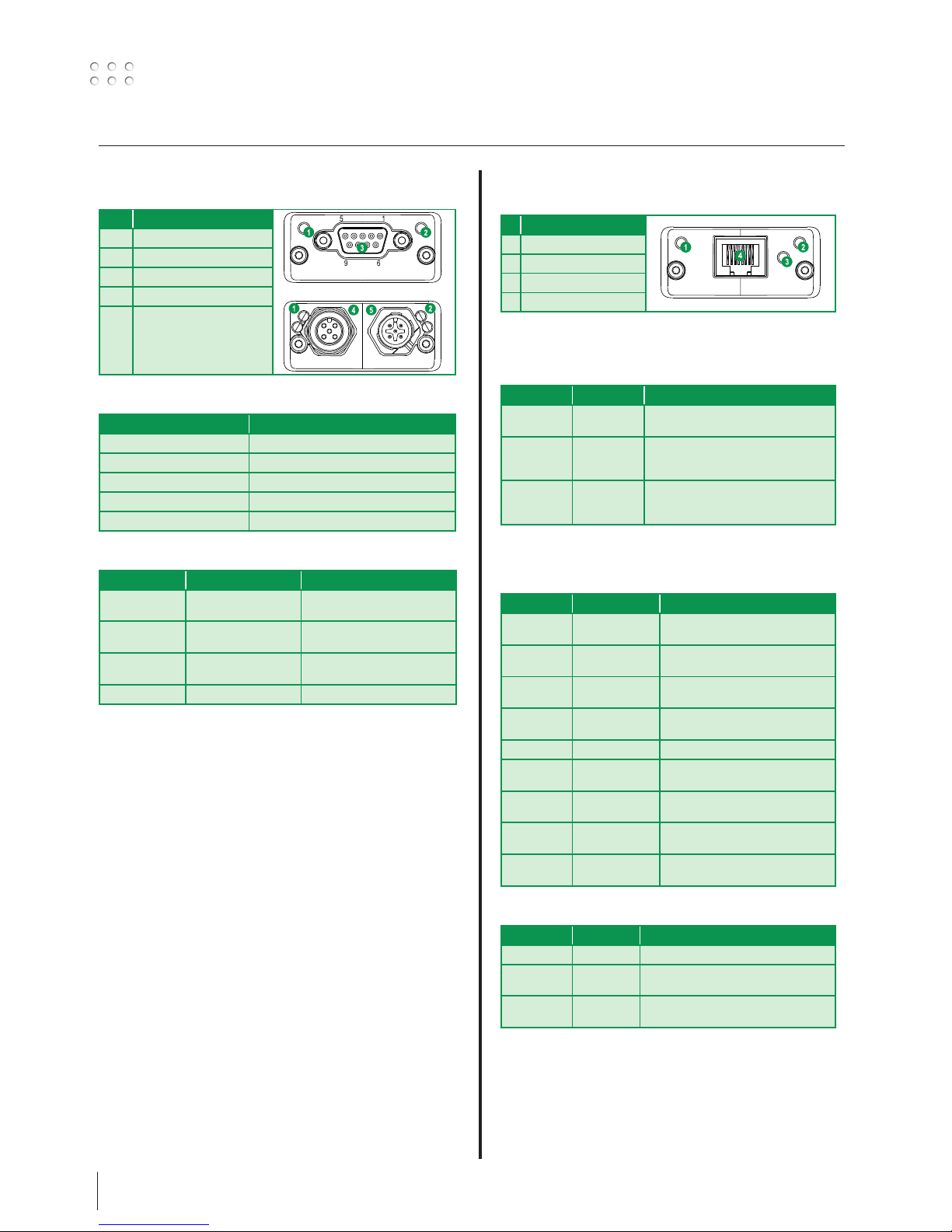
Tilslutning af svejseinstallationen
Controller
d
ROBOT/PLC
controller
3 vindinger
gennem kerne
17440005
RWF 30
SIGMA SELECT ROBO
REMOTE
Anybus
kommunikation
b
4
e
c
a
2
Anybus
interface
1
3
Hovedkomponenter:
1. Interface
2. Svejseinverter
3. Trådboks - RWF 30
4. Remote fjernbetjening
Kabler og fittings:
a. Signalkabel til robot controller
b. CAN kommunikationskabel til svejseinverter
c. Mellemkabel, gas- og 2 x svejsekabel og CAN
d. Svejsebrænder
e. Svejsereturkabel
Svejseproces Afstand til arbejdsemne
( + )
Total kabellængde i svejsekredsløb
( + + )
Total længde af CAN kabel
( + )
MIG – puls 10 m 20 m 30 m
MIG – ingen puls 30 m 60 m 30 m
cc c
b
d d e
Installering af
Anybus-modul
1. Vigtigt! Indsæt stikket lige i hullet, når
Anybus-modulet skal monteres.
2. Skub stikket på plads med forsigtighed.
3. Skru Anybus-modulet fast ved hjælp af
skruerne.
1
2
3
Kabelstørrelser
Svejsestrøm DC PULS
200 A 35 mm² 35 mm²
300 A 50 mm² 70 mm²
400 A 95 mm² / 2x50 mm² 95 mm² / 2x50 mm²
550 A 2x70 mm² 2x70 mm²
BEMÆRK:
DEFEKTE TILSLUTNINGER
DÆKKES IKKE AF GARANTIEN!!!

6
Tilslutning og ibrugtagning
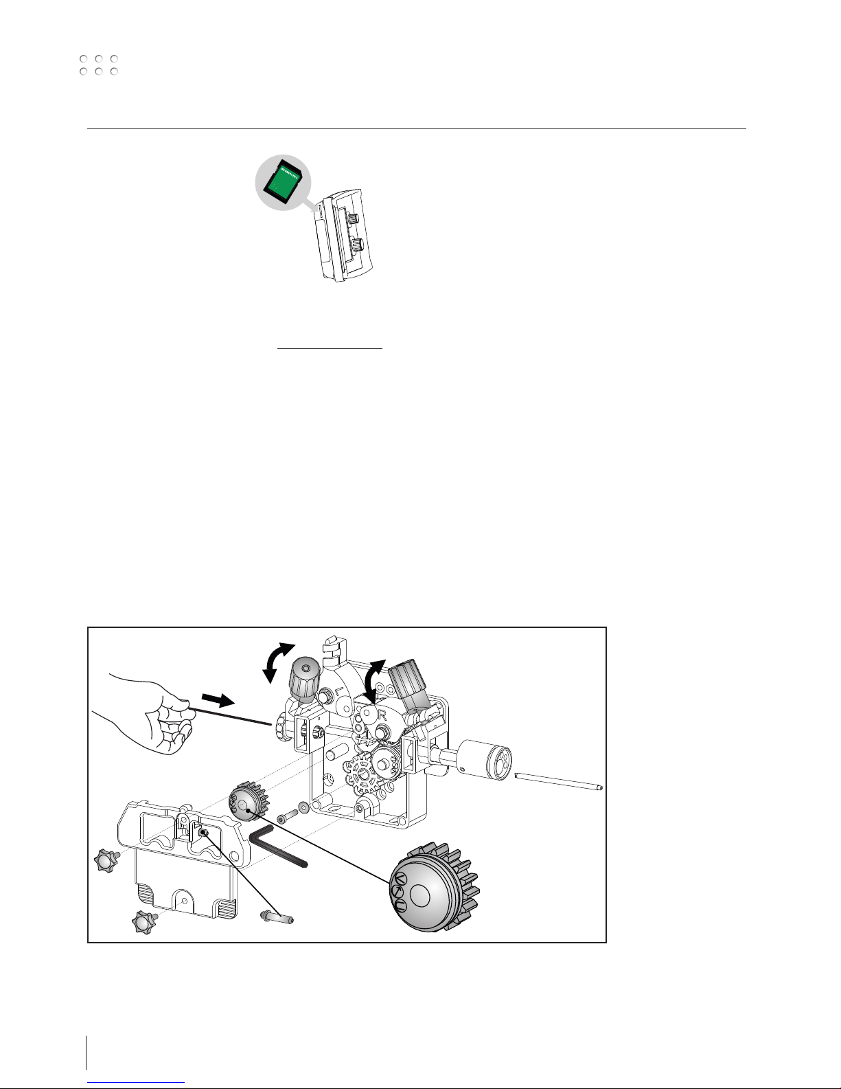
x4
Montering af dele i trådfremføring
Fingerskruens tryk
indstilles, således at
trådtrisserne netop glider
på tråden, når denne
bremses ved kontaktdysen
Software opdatering
• Indsæt SD-kortet
• Tænd maskinen.
• Vent indtil enheden
indikerer, at opdatering er
afsluttet
• Sluk maskinen og tag SDkortet ud.
• Maskinen er nu klar til brug.
Strømkilde og alle tilkoblede enheder får den nye software
indlæst.
Softwaren kan downloades fra http://migatronic.com
Licens SW
Ved tilkøb af ekstra programmer eller særlige funktioner skal
MigaLic.dat filerne indlæses på samme vis som SW-pakker. Husk
at gemme en sikkerhedskopi af filerne.
MigaLic.txt filen indeholder information om maskinens
licensnummer og de gemte licenser på SD-kort.
7
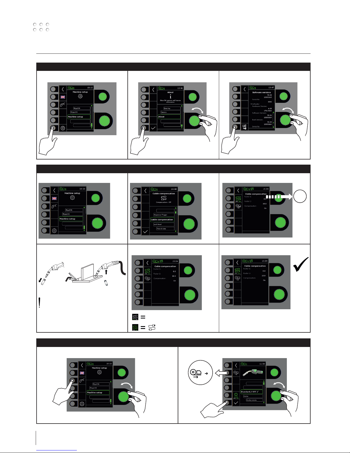
Specielle funktioner
Setup wizard
I II
III
IV V VI
Låsefunktion
I II III

8
Specielle funktioner
Software / Licenser
I II
III
Kabelkompensering (kalibrering af modstand i svejseslange)
I II III
IV V
1
2
Std.
Svejseemnets overflade skal være ren for
at sikre god kontakt med brænderen.
Torch setup
I II
12
- - -

9
Fejlhåndtering
SIGMA Select Robo har et avanceret selvbeskyttelsessystem indbygget. Ved fejl lukker maskinen automatisk for gastilførslen, afbryder
svejsestrømmen og stopper trådfremførelsen.
Udvalgte fejl:
Kølefejl
Kølefejl vises i tilfælde af at kølevandet ikke kan cirkulere som følge af forkert tilslutning eller tilstopning.
Kontroller at køleslangerne er korrekt tilsluttet, efterfyld vandbeholderen og efterse svejseslange og tilslutningsstudser. Kølefejlen
afmeldes med et kort tryk på P-knappen.
Gasfejl (IGC)
Gasfejl kan skyldes for lavt eller for højt tryk på gastilførslen.
Kontroller at trykket på gastilførslen er højere end 2 bar og mindre end 6 bar, svarende til 5 l/min og 27 l/min.
Gasfejl kan sættes ud af funktion ved at indstille manuel gasflow til 27l/min. Gasfejlen afmeldes med et kort tryk på P-knappen.
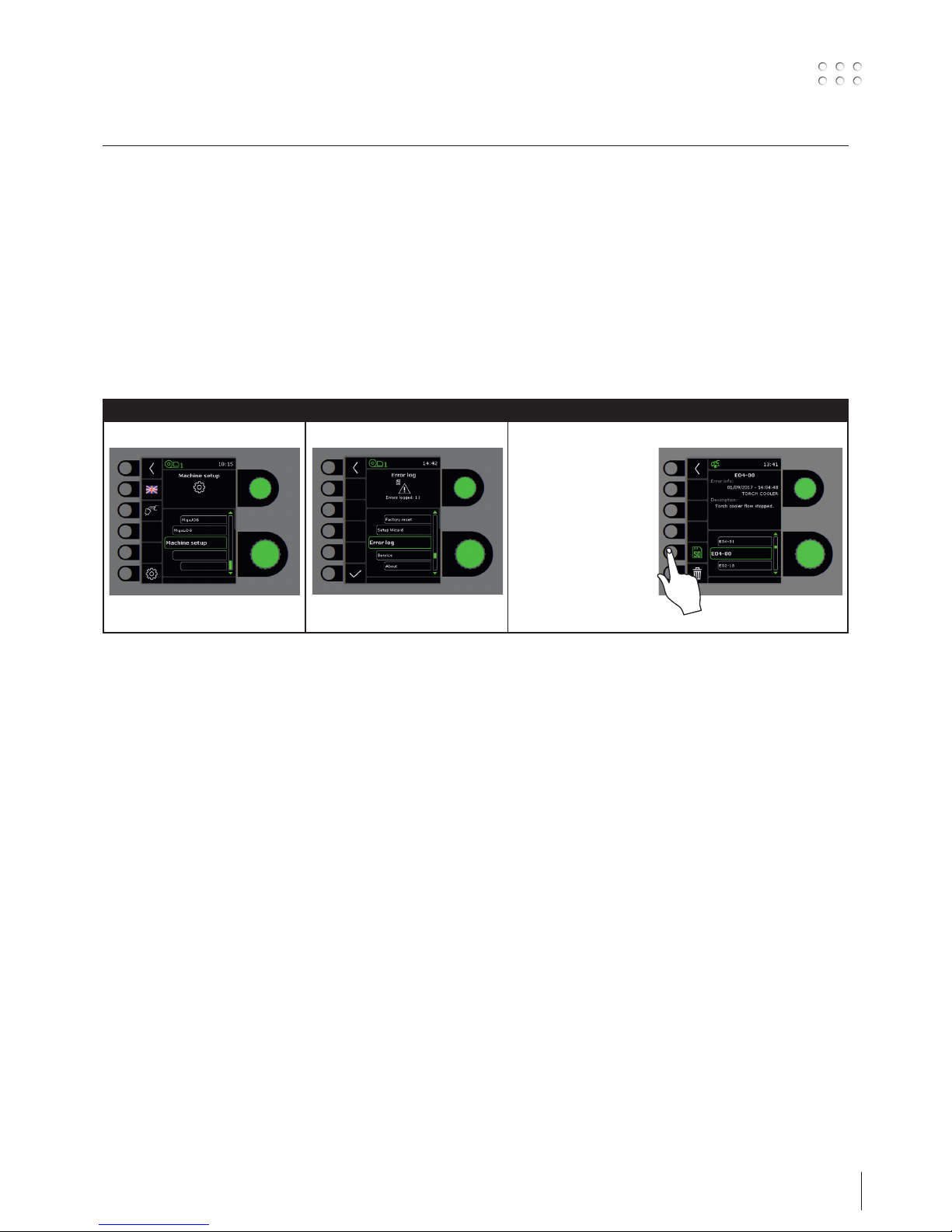
Fejllog
I II III
Fejllog
Alle fejl gemmes i
maskinens fejllog under
menuen Service.
Fejlloggen kan distribueres,
når der indsættes et
SD-kort og trykkes på
følgende tast:
Fejlloggen er nu gemt på
SD-kortet.
Fejlloggen kan nulstilles,
når der trykkes på tasten ud
for skraldespanden.
10
Tekniske data 1
1) Dette udstyr er i overensstemmelse med IEC 61000-3-12, forudsat at nettets
kortslutningseffekt Ssc ved tilslutningsstedet er større end eller lig med
de opgivne data i ovenstående skema. Installatøren eller brugeren af
udstyret er ansvarlig for at sikre, evt. i samråd med forsyningsdistributøren,
at udstyret er tilsluttet til en netforsyning med en kortslutningseffekt Ssc
større end eller lig med de opgivne data i ovenstående skema.
2) S Maskiner opfylder de krav der stilles under anvendelse i områder med
forøget risiko for elektrisk chok
3) Angiver at maskinen er beregnet for såvel indendørs som udendørs
anvendelse
STRØMKILDE 300 300 IAC 400 400 IAC 550
Netspænding ±15% (50-60Hz), V 3x400 3x400 3x400 3x400 3x400
Minimum generatorstørrelse, kVA 16 19 27 29 40
1)
Minimum kortslutningseffekt, MVA TBD 4,3 6,0 6,0 9,5
Sikring, A 16 16 20 20 35
Netstrøm, effektiv, A 11,0 16 17,5 16,5 27,2
Netstrøm, max., A 15,4 18,3 26,0 28,2 39,2
Effekt, 100%, kVA 9,0 11,1 12,1 11,4 18,9
Effekt, max., kVA 10,7 12,7 18,0 19,5 27,1
Effekt, tomgang, W 30 30 30 30 30
Virkningsgrad 0,85 0,85 0,85 0,8 0,90
Powerfaktor 0,90 0,90 0,90 0,90 0,90
MIG MMA MIG MMA MIG MMA MIG MMA MIG MMA
Strømområde, A 15-300 15-250 15-300 15-300 15-400 15-400 15-400 15-400 15-550 15-550
Intermittens, 100% 20°C, A/V 290/28,5 250/30,0 300/29,0 300/32,0 345/31,5 345/33,8 310/29,5 310/32,5 475/37,8 475/39,0
Intermittens, maks. 20°C, A/%/V 400/65/34,0 400/65/36,0 400/60/34,0 400/60/36,0 550/60/41,5 550/60/42,0
Intermittens, 100% 40°C, A/V 220/25,0 220/28,8 270/27,5 270/30,8 300/29,0 300/32,0 280/28,0 280/31,2 430/35,5 430/37,2
Intermittens, 60% 40°C, A/V 240/26,0 230/29,2 370/32,5 370/34,8 350/31,5 350/34,0 510/39,5 510/40,4
Intermittens, maks. 40°C, A/%/V 300/25/29,0 250/40/30,0 300/80/29,0 300/80/32,0 400/50/34,0 400/45/36,0 400/40/34,0 400/40/36,0 550/50/41,5 550/50/42,0
Tomgangsspænding, V 50-60 65-70 65-70 65-70 75-80
2)
Anvendelsesklasse, C / S
S/CE / S/CE S/CE / S/CE S/CE / S/CE S/CE / S/CE S/CE / S/CE
3)
Beskyttelsesklasse IP23S IP23 IP23 IP23 IP23
Normer, C
Normer, S
IEC60974-1, IEC60974-5, IEC60974-10 Cl. A
IEC60974-1, IEC60974-10 Cl. A
Dimensioner C (HxBxL), mm
Dimensioner S (HxBxL), mm
700x260x735
454x260x735
700x260x735
454x260x735
700x260x735
454x260x735
700x260x735
454x260x735
700x260x735
454x260x735
Vægt C / S, kg 36,9 / 26 53 / 36 52 / 35 53 / 53 / 36
STRØMKILDE 300 Boost
Netspænding ±10% (50-60Hz), V 208-380 380-440
Minimum generatorstørrelse, kVA 16 16
1)
Minimum kortslutningseffekt, MVA 3,75
Sikring, A 20 16
Netstrøm, effektiv, A 19,5 10,6
Netstrøm, max., A 31,6 16,2
Effekt, 100%, kVA 7,1 7,0
Effekt, max., kVA 11,0 10,6
Effekt, tomgang, W 45 45
Virkningsgrad 0,81 0,82
Powerfaktor 0,95 0,95
MIG MMA MIG MMA
Strømområde, A 15-300 15-250 15-300 15-250
Intermittens, 100% 20°C, A/V 250/26,5 250/26,5
Intermittens, maks. 20°C, A/%/V 300/40/29,0 300/40/29,0
Intermittens, 100% 40°C, A/V 200/24,0 200/28,0 200/24,0 200/28,0
Intermittens, 60% 40°C, A/V 210/24,5 210/28,4 210/24,5 210/28,4
Intermittens, maks. 40°C, A/%/V 300/25/29,0 250/35/30,0 300/25/29,0 250/35/30,0
Tomgangsspænding, V 50-60
2)
Anvendelsesklasse, C / S
S/CE / S/CE
3)
Beskyttelsesklasse 23S
Normer, C
Normer, S
IEC60974-1, IEC60974-5, IEC60974-10 Cl. A
IEC60974-1, IEC60974-10 Cl. A
Dimensioner C (HxBxL), mm
Dimensioner S (HxBxL), mm
700x260x735
454x260x735
Vægt C / S, kg 45 / 34
11
Tekniske data 2
EU-OVERENSSTEMMELSESERKLÆRING
MIGATRONIC A/S
Aggersundvej 33
9690 Fjerritslev
Danmark
erklærer, at nedennævnte maskine
Type: SIGMA SELECT ROBO
er i overensstemmelse med bestemmelserne i
direktiverne 2014/35/EU
2014/30/EU
2011/65/EU
Europæiske EN/IEC60974-1
standarder: EN/IEC60974-2
EN/IEC60974-5
EN/IEC60974-10 (Class A)
Udfærdiget i Fjerritslev 01.03.2018
Niels Jørn Jakobsen
CEO
BETJENING PROCES VÆRDIOMRÅDE
Valg af tastemetode, 2-takt/4-takt MIG/MAG 2/4
Kontrol af strøm/spænding/trådhastighed - Lokal/brænder/fjernkontrol
Rangering af tråd MIG/MAG
Brænderkøling - Vandkølet/luftkølet
Hotstart % MMA 0,0-100,0
Hotstart-tid, sek. MMA 0,0-20,0
Arc power, % MMA 0,0-150,0
Gasforstrømning, sek. MIG/MAG 0,0-10,0
Krybestart, m/min MIG/MAG 0,5-24,0
Hotstart, % Synergisk -99-(+)99
Hotstart tid, sek. Synergisk 0,0-20,0
Strømsænkningstid, sek. Synergisk 0,0-10,0
Stopstrøm, A Synergisk 0-100
Stopstrømtid, sek. Synergisk 0,0-10,0
Gasefterstrømning, sek. MIG 0,0-20,0
Sekvenstimer / punktsvejsetid, sek. MIG 0,0-50,0
DUO Plus™ effekttrim, % MIG 0-50
DUO Plus™ tid, sek. MIG 0,1-9,9
Elektronisk drossel MIG -5,0-(+)5,0
Sekvens, sekvenstrin MIG 9
KØLEMODUL MCU 1300
Køleeffekt (1 l/min), W 1300
Køleeffekt (1,5 l/min), W 1600
Tankkapacitet, liter 5
Flow, bar - °C - l/min 3,0-60-1,5
Maks. tryk, bar 5
Normer IEC60974-2,
IEC60974-10 CL.A
Dimensioner (HxBxL), mm 207x260x680
Vægt, kg 20

12
Tekniske data Anybus moduler
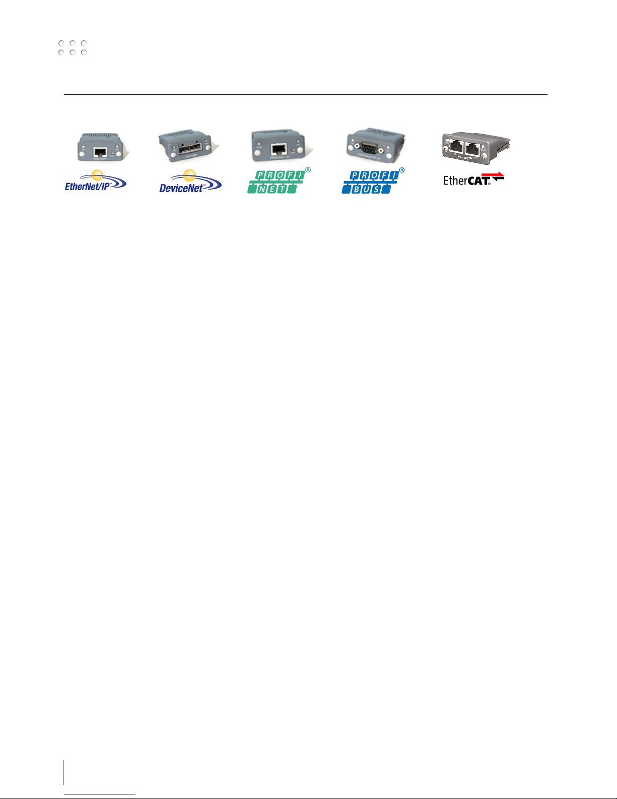
Supported Anybus communication interface
General Technical Data
Certification UL, cUL File number E214107
CE - Declaration of Pre-Conformity
Emission EN 61000-6-4
EN55011 Radiated emission
EN55011 Conducted emission
Immunity EN 61000-6-2 EN61000-4-2 Electrostatic discharge
EN61000-4-3 Radiated immunity
EN61000-4-4 Fast transients/burst
EN61000-4-5 Surge immunity
EN61000-4-6 Conducted immunity
DeviceNet
Vendor ID / Name: 90 (005Ah) / (HMS Industrial Networks)
Product Name: ‘Anybus-CompactCom DeviceNet’
ProdTypStr: Generic Device
Device Type: 0 (0000h)
Product Code: 98 (0062h) (Anybus-CompactCom DeviceNet)
Baud rates: 125kbps – 250kbps - 500kbps
Major Revision: 2
Minor Revision: 1
The Anybus CompactCom DeviceNet module accepts 11-25 V on the industrial network side of the module. Maximum current
consumption at 11-25 V is 36-38 mA/module.
Ethernet IP
Vendor ID / Name: 90 (005Ah) / (HMS Industrial Networks)
Product Name: ‘Anybus-CC EtherNet/IP’
ProdTypStr: Generic Device
Device Type: 0 (0000h) (Generic Device)
Product Code: 99 (0063h) (Anybus-CompactCom EtherNet/IP)
Assembly instance input: 100 (0064h)
Assembly instance output: 150 (0096h)
Configuration instance: 1 (0001h)
Major Revision: 2 (0002h)
Minor Revision: 11 (000Bh)
The Ethernet interface supports 10/100Mbit, full or half duplex operation.
ProfiNET
Vendor ID: 268 (010Ch) (HMS Industrial Networks)
Device Type: 7 (0007h) (Anybus-CompactCom PROFINET IO)
Station Type: ‘ABCC-PRT’
ProfiBus
IM Manufacturer ID: 268 (010Ch) (HMS Industrial Networks)
IM Order ID: ‘ABCC-DPV1’
IM Profile ID: 62976 (F600h) (Generic Device)
IM Profile Specific Type: 4 (0004h) (Communication Module)
IM Version: 257 (0101h)
IM Supported: 30 (001Eh) (IMO..4 supported)
EtherCAT
Vendor ID E000 001Bha (HMS Industrial Networks Secondary Vendor ID, has to be replaced by Vendor ID of end product vendor.)
a. For firmware revision 1.02 and later.
Product Code 0000 0034h (Anybus CompactCom EtherCAT)
Device Name ‘Anybus-CC EtherCAT’
Serial Number (Assigned during manufacturing)
13
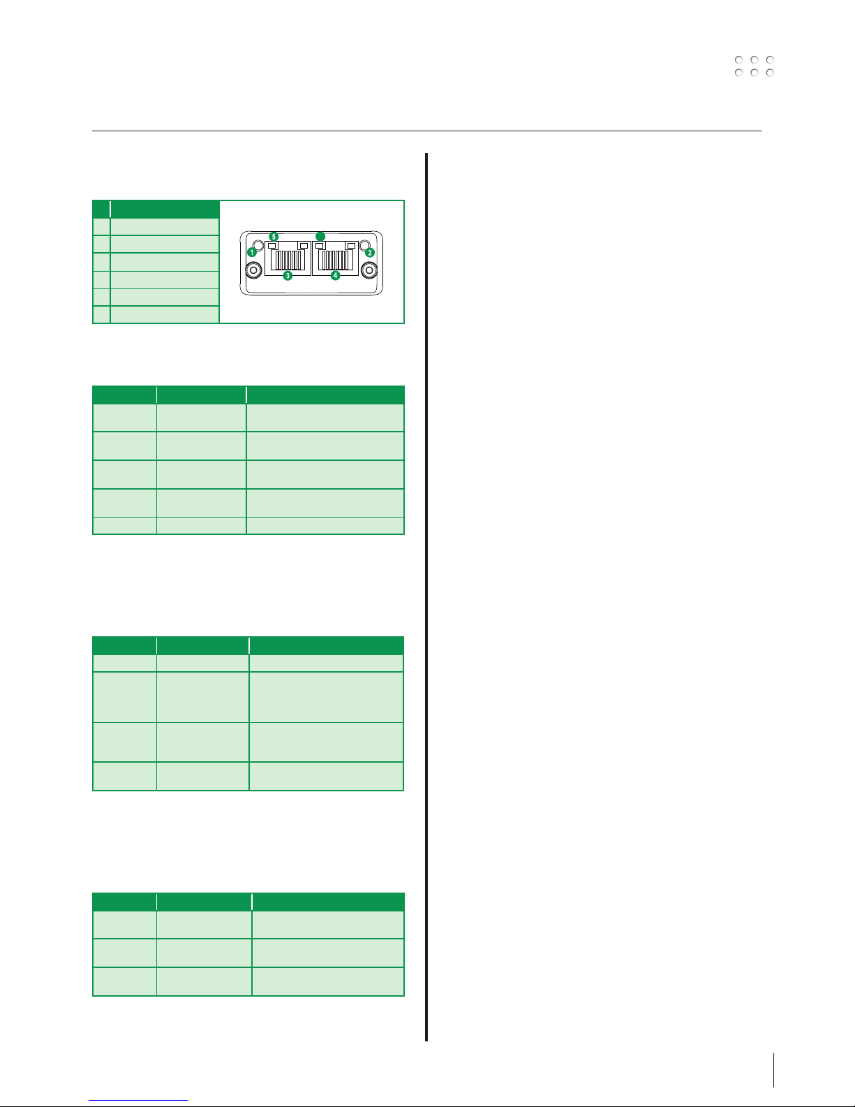
Anybus indikatorer
DeviceNet
# Element
1 Netværksstatus LED
2 Modulstatus LED
3 DeviceNet tilslutning
4 M12 hunstik
5 M12 hanstik
Network Status
Tilstand Indikation
Slukket Ikke online / Ingen strøm
Grøn Online, en eller flere tilslutninger
etableret
Grøn, blinkende (1 Hz) Online, ingen tilslutninger etableret
Rød Kritisk linkfejl
Rød, blinkende (1 Hz) En eller flere tilslutninger på pause
Afvekslende rød/grøn Selvtest
Module Status
Tilstand Indikation
Slukket Ingen strøm
Grøn Normal drift
Grøn, blinkende(1 Hz) Manglende eller ufuldstændig konfigu-
ration, enheden mangler igangsætning
Rød Fejl(ene) kan ikke udbedres
Rød, blinkende (1 Hz) Fejl(ene) kan udbedres
Afvekslende rød/grøn Selvtest
DeviceNet stikforbindelse
Denne stikforbindelse sørger for forbindelse
Pin Signal Beskrivelse
1 V- Negativ bus forsyningsspænding
2 CAN_L CAN lav bus-linje
3 SHIELD Kabelbeskyttelse
4 CAN_H CAN høj bus-linje
5 V+ Positiv bus forsyningsspænding
EtherNet IP
# Element
1 Netværksstatus LED
2 Modulstatus LED
3 Link/Aktivitet
4 Ethernet Interface
Network Status LED
LED tilstand Beskrivelse
Slukket Ingen strøm eller ingen IP-adresse
Grøn Online, en eller flere tilslutninger
etableret (CIP klasse 1 eller 3)
Grøn, blinkende Online, ingen tilslutninger etableret
Rød Dobbelt IP-adresse, FATAL fejl
Rød, blinkende En eller flere tilslutninger på pause (CIP
Klasse 1 eller 3)
Modul Status LED
Bemærk: Der udføres en testsekvens på denne LED
under opstart
LED tilstand Beskrivelse
Slukket Ingen strøm
Grøn Kontrolleret af en scanner i Run tilstand
Grøn, blinkende Ikke konfigureret, eller scanner er ikke
i drift
Rød Alvorlig fejl (EXCEPTION-tilstand, FATAL
fejl etc.)
Rød, blinkende Fejl, der kan udbedres
LINK/Aktivitet LED
LED tilstand Beskrivelse
Off Ingen link, ingen aktivitet
Grøn Link etableret
Grøn, flakkende Aktivitet
1
8
14
Anybus indikatorer
PROFIBUS
# Element
1 Driftsfunktion
2 Status
3 PROFIBUS tilslutning
4 M12 hunstik
5 M12 hanstik
Driftstilstand
Tilstand Indikation
Slukket Ikke online / Ingen strøm
Grøn Dataudveksling
Blinkende grøn Slet
Blinkende rød (1 blink) Parameterfejl
Blinkende rød (2 blink) PROFIBUS konfigurationsfejl
Status
Tilstand Indikation Bemærkninger
Slukket Ikke initialiseret Anybus tilstand = ‘OPSTILLING¨’
eller ‘NW_INIT’
Grøn Initialiseret Anybus modul har forladt
‘NW_INIT’ tilstand
Blinkende grøn Initialiseret, diagnostisk
event(s) til stede
Udvidet diagnostisk bit er
indstillet
Rød Fejltilstand Anybus tilstand = ‘EXCEPTION’
PROFINET IP
# Element
1 Netværksstatus LED
2 Modulstatus LED
3 Link/Aktivitet LED
4 Ethernet Interface
Netværk Status LED
Bemærk: Der udføres en testsekvens på denne LED under
opstart
LED Tilstand Beskrivelse Bemærkninger
Off Offline - Ingen strøm
- Ingen tilslutning med IO Controller
Grøn Online
(RUN)
- Tilslutning med IO Controller
etableret
- IO Controller i RUN tilstand
Grøn,
blinkende
Online
(STOP)
- Tilslutning med IO Controller
etableret
- IO Controller i STOP tilstand
Modul Status LED
Bemærk: Der udføres en testsekvens på denne LED under
opstart
LED Tilstand Beskrivelse Bemærkninger
Off Ikke
Initialiseret
Ingen strøm - eller - Modul i
‘OPSTILLING’ or ‘NW_INIT’ tilstand
Grøn Normal drift Modul har skiftet fra ‘NW_INIT’
tilstand
Grøn,
1 blink
Diagnostiske
event(s)
Diagnostiske event(s) til stede
Grøn,
2 blink
Blink Brugt af engineering værktøjer til
at identificere knude på netværk
Rød Exception-fejl Modul i tilstand ‘EXCEPTION’
Rød, 1 blink Konfigurations-
fejl
Expected Identification varierer
fra Real Identification
Rød,
2 blink
IP Adressefejl IP adresse ikke indstillet
Rød,
3 blink
Fejl i stationsnavn
Stationsnavn ikke indstillet
Rød,
4 blink
Intern fejl Modul er stødt på en større intern
fejl
LINK/Aktivitet LED
LED Tilstand Beskrivelse Bemærkninger
Slukket Ingen link Ingen link, ingen kommunikation
Grøn Link Ethernet link etableret, ingen
kommunikation
Grøn,
flakkende
Aktivitet Ethernet link etableret,
kommunikation til stede
Ethernet Interface
Ethernet interfacet kører ved 100 Mbit, fuld duplex, med
autonegotiation aktiv som standard.
1
8
15
Anybus indikatorer
EtherCAT
EtherCAT Connector
# Element
1 RUN LED
2 FEJL LED
3 EtherCAT (port 1)
4 EtherCAT (port 2)
5 Link/Aktivitet (port 1)
6 Link/Aktivitet (port 2)
RUN LED
Denne LED afspejler status på CoE (CANopen over EtherCAT)
kommunikation
LED Tilstand Indikation Beskrivelse
Slukket INIT CoE enhed i ‘INIT’-tilstand (eller
ingen strøm)
Grøn OPERATIONAL CoE enhed i
‘OPERATIONAL’-tilstand
Grøn,
blinkende
PREOPERATIONAL
CoE enhed i
‘PRE-OPERATIONAL’-tilstand
Grøn,
enkelt blink
SAFEOPERATIONAL
CoE enhed i
‘SAFE-OPERATIONAL’-tilstand
Rød
a
(Fatal Event) -
a. Hvis RUN og ERR bliver rød, indikerer det en fatal event, der
tvinger bus interfacet til fysisk passiv tilstand.
Kontakt HMS teknisk support.
ERR LED
Denne LED indikerer EtherCAT kommunikationsfejl etc.
LED Tilstand Indikation Beskrivelse
Slukket Ingen fejl Ingen fejl (eller ingen strøm)
Rød,
blinkende
Ugyldig
konfiguration
Tilstandsændring modtaget fra
master er ikke mulig på grund af
ugyldige register- eller objektindstillinger.
Rød,
dobbelt
blink
Application
watchdog timeout
Sync manager watchdog timeout
Rød
a
Application
controller failure
Anybus-modul i EXCEPTION
a. Hvis RUN og ERR bliver rød, indikerer det en fatal event, der
tvinger bus interfacet til fysisk passiv tilstand.
Kontakt HMS teknisk support.
LINK/Aktivitet
Disse LED’er indikerer EtherCAT linkstatus og aktivitet.
LED Tilstand Indikation Beskrivelse
Slukket Ingen link Link ikke registreret (eller ingen
strøm)
Grøn Link registreret,
ingen aktivitet
Link registreret, ingen trafik
detekteret
Grøn,
flakkende
Link registreret,
aktivitet detekteret
Link registreret, trafik
detekteret
6

16
17
Connection and operation
1
0
1
Warning
Read warning notice and instruction
manual carefully prior to initial
operation and save the information
for later use.
Permissible installation
Mains connection
Connect the machine to the correct mains supply. Please read
the type plate (U1) on the rear side of the machine.
2
Connection of shielding gas
Connect the gas hose, which branches off from the back panel
of the welding machine (3), to a gas supply with pressure
regulator (2-6 bar). (Note: Some types of pressure regulators
require an output pressure of more than 2 bar to function
optimally).
Important!
In order to avoid destruction of plugs and
cables, good electric contact is required
when connecting earth cables and welding
hoses to the machine.
WARNING
When you activate the torch trigger,
there is voltage applied to the welding
wire and electrode.
Connection of welding hose
Lift instructions
(Lifting kit no. 78857054)
Recommended cable dimensions
Welding current DC PULSE
200 A 35 mm² 35 mm²
300 A 50 mm² 70 mm²
400 A 95 mm² / 2x50 mm² 95 mm² / 2x50 mm²
550 A 2x70 mm² 2x70 mm²
Welding process Distance to work piece
(a+b)
Total cable length in
welding circuit (a+b+c)
MIG - IAC and pulse 10 m 20 m
MIG - non pulse 30 m 60 m
c
a
b
L1
L2
L3
N
yellow/green
brown
black
grey
3x208-440V (boost)
3x400V

18
Connection and operation
11
GAS
2-6 bar
Power
F
F
F
1
2
3
4a
4b
5
5
6
6
7
7
8
9
10
1. Mains connection
2. Power switch on/off
3. Connection of shielding gas
4a. Connection of cooling hose, return (red)
4b. Connection of cooling hose, flow (blue)
5. Dinse connection -
6. Dinse connection +
7. CAN connection
8. Fieldbus module
9. Refill of cooling liquid
10. Cooling liquid level control (Min/Max)
11. Assembly plate
MIGA_CFG
DOCUMENTS
Devicenet
EtherCAT
Profibus
Profinet
Ethernet-IP
Config.
Robot / PLC setup
Migatronic’s standard configuration file (10010208) is
loaded in SIGMA SELECT.
The SD card included in the supply contains additional
configuration files and setup files required by some robots
and PLCs.
Load the MIGA_CFG/DOCUMENTS folders on your PC.
Each folder contains EDS or GSD files, user manuals, quick
guides and various Anybus module documentation for
communication devices.
19
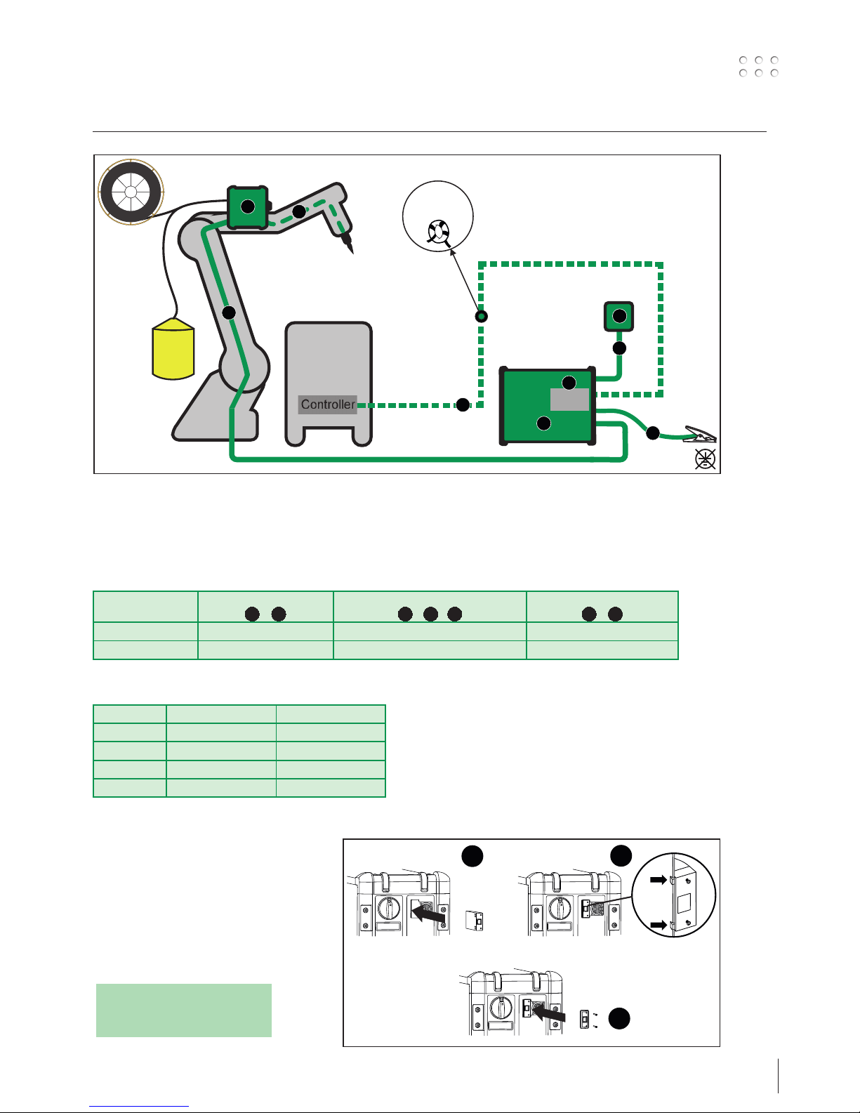
How to connect the installation
Controller
d
ROBOT/PLC
controller
3 windings
through core
17440005
RWF 30
SIGMA SELECT ROBO
REMOTE
Anybus
communication
b
4
e
c
a
2
Anybus
interface
1
3
Main components:
1. Interface
2. Welding inverter
3. Wire feed unit - RWF 30
4. Remote control
Cables and fittings:
a. Signal cable for robot controller
b. CAN communication cable for welding inverter
c. Interconnection, gas and 2xwelding cable and CAN
d. Welding torch
e. Welding return cable
Welding process Distance to work piece
( + )
Total cable length in welding circuit
( + + )
Total length of CAN cable
( + )
MIG – pulse 10 m 20 m 30 m
MIG – non pulse 30 m 60 m 30 m
cc c
b
d d e
Installing
the Anybus module
1. Important! Once you have installed the
Anybus module, insert the plug straight into
the hole.
2. Press the plug slightly into position.
3. Tighten the Anybus module using the screws.
1
2
3
Cable dimensions
Welding current DC PULSE
200 A 35 mm² 35 mm²
300 A 50 mm² 70 mm²
400 A 95 mm² / 2x50 mm² 95 mm² / 2x50 mm²
550 A 2x70 mm² 2x70 mm²
NOTE:
DEFECTIVE CONNECTORS
ARE NOT COVERED BY WARRANTY!!!
20
Connection and operation
x4
Assembly of parts in wire feed unit
The pressure of the
thumbscrew is adjusted to
allow the wire feed roll
just to slide on the wire
when this is stopped at
the contact tip
Software update
• Insert the SD-card
• Turn on the machine
• Wait until the unit indicates
that the update is complete
• Turn off the machine and
remove the SD card.
• The machine is now ready
for use.
New software will be loaded into power source and all
connected units.
The software can be downloaded from http://migatronic.com
Licence SW
If you purchase additional licences for programs or special
funtions, load the MigaLic.dat files like the software packages.
Note! Create a backup of the files.
The MigaLic.txt file contains information about licence number
and licences saved on SD card.

21
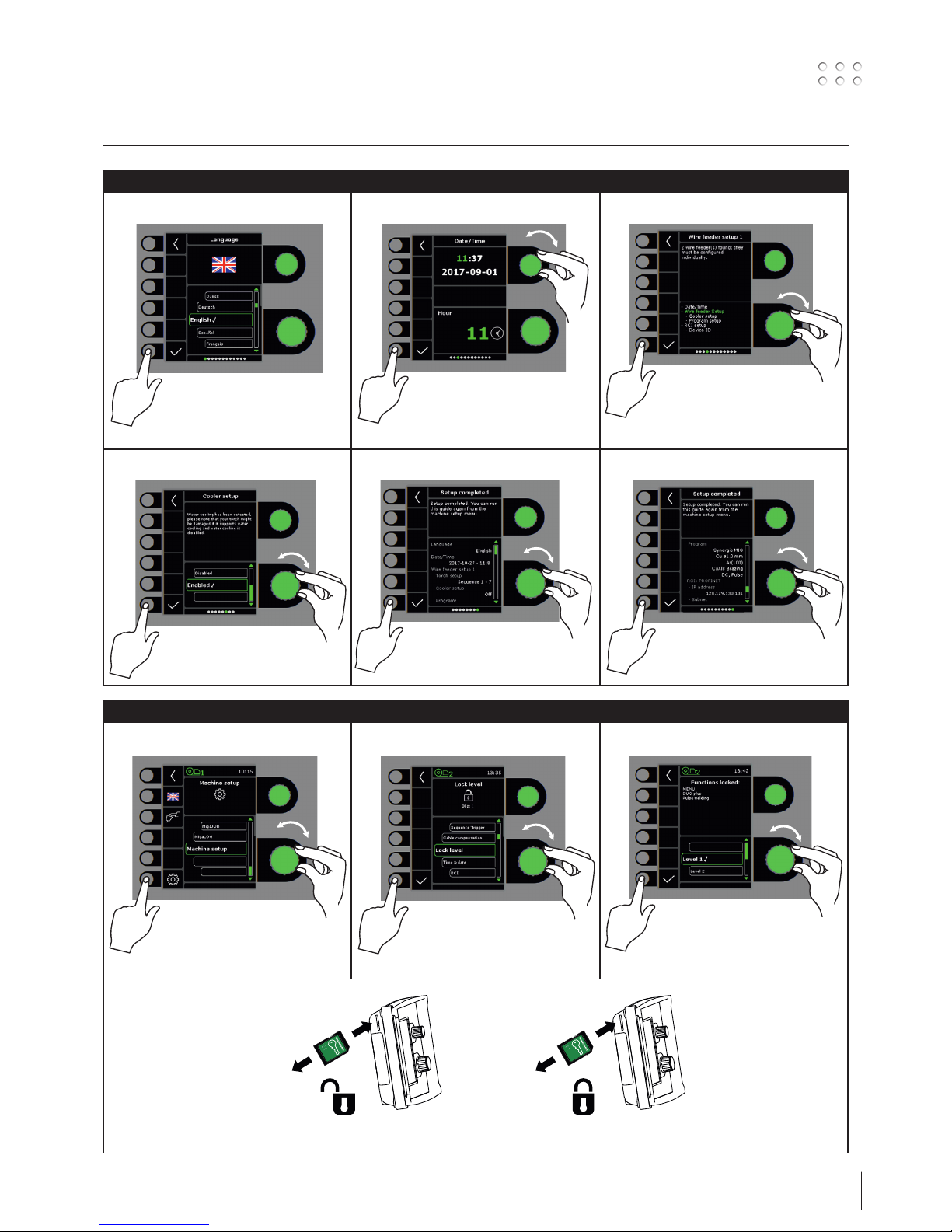
Special functions
Setup wizard
I II
III
IV V VI
Lock function
I II III
22
Special functions
Software / Licences
I II
III
Cable compensation (calibration of resistance in welding hose)
I II III
IV V
1
2
Std.
The surface of the workpiece must be
clean to ensure good contact with the
torch.
Torch setup
I II
12
- - -
23
Error handling
SIGMA Select Robo has a sophisticated built-in self-protection system. The machine automatically stops the gas supply, interrupts the
welding current and stops the wire feeding in case of an error.
Selected errors:
Torch cooling fault
Cooling fault is indicated on machines in case of insufficiant circulation of the cooling liquid due to faulty connection, defective parts or
choking. Check that the cooling hoses are correctly connected, top up the water tank and check welding hose and branches.
The cooling fault is cancelled by pressing shortly on the P-key pad.
Gas control fault (IGC)
Gas fault exists due to a to low or high gas flow.
Make sure that the pressure on the gas flow is higher than 2 bar and less than 6 bar, corresponding to 5 l/min and 27 l/min.
The fault is disconnected by adjusting the manual gas flow to 27 l/min. The gas fault is reset by a short pressure on the P-key pad.
Error log
I II III
Error log
All errors are saved in the
machine error log in the
menu Service.
The error log can be
distributed, when inserting
a SD-card and pressing the
following key:
The error log is now saved
at the SD-card.
The error log can be reset
when pressing the key pad
with the trash bin.

24
Technical data 1
1) This equipment complies with IEC 61000-3-12 provided that the shortcircuit power Ssc of the grid at the interface point is greater than or equal
to the stated data in the abovementioned table. It is the responsibility
of the installer or user of the equipment to ensure, by consultation with
the distribution network operator if necessary, that the equipment is
connected only to a supply with a short-circuit power Ssc greater than or
equal to the stated data in the abovementioned table.
2) S This machine meets the demand made for machines which are to
operate in areas with increased hazard of electric chocks.
3) Equipment marked IP23/IP23S is designed for indoor and outdoor
applications.
POWER SOURCE 300 300 IAC 400 400 IAC 550
Mains voltage ±15% (50-60Hz), V 3x400 3x400 3x400 3x400 3x400
Minimum generator size, kVA 16 19 27 29 40
1)
Minimum short-circuit power, MVA TBD 4.3 6.0 6.0 9.5
Fuse, A 16 16 20 20 35
Mains current, effective, A 11.0 16 17.5 16.5 27.2
Mains current, max., A 15.4 18.3 26.0 28.2 39.2
Power, 100%, kVA 9.0 11.1 12.1 11.4 18.9
Power, max., kVA 10.7 12.7 18.0 19.5 27.1
Power, open circuit, W 30 30 30 30 30
Efficiency 0.85 0.85 0.85 0.8 0.90
Power factor 0.90 0.90 0.90 0.90 0.90
MIG MMA MIG MMA MIG MMA MIG MMA MIG MMA
Current range, A 15-300 15-250 15-300 15-300 15-400 15-400 15-400 15-400 15-550 15-550
Duty cycle, 100% 20°C (MIG), A 290/28.5 250/30.0 300/29.0 300/32.0 345/31.5 345/33.8 310/29.5 310/32.5 475/37.8 475/39.0
Duty cycle, max. 20°C (MIG), A/%/V 400/65/34.0 400/65/36.0 400/60/34.0 400/60/36.0 550/60/41.5 550/60/42.0
Duty cycle, 100% 40°C (MIG), A/V 220/25.0 220/28.8 270/27.5 270/30.8 300/29.0 300/32.0 280/28.0 280/31.2 430/35.5 430/37.2
Duty cycle, 60% 40°C (MIG), A/V 240/26.0 230/29.2 370/32.5 370/34.8 350/31.5 350/34.0 510/39.5 510/40.4
Duty cycle, max. 40°C (MIG), A/%/V 300/25/29.0 250/40/30.0 300/80/29.0 300/80/32.0 400/50/34.0 400/45/36.0 400/40/34.0 400/40/36.0 550/50/41.5 550/50/42.0
Open circuit voltage, V 50-60 65-70 65-70 65-70 75-80
2)
Sphere of application, C / S
S/CE / S/CE S/CE / S/CE S/CE / S/CE S/CE / S/CE S/CE / S/CE
3)
Protection class IP23S IP23 IP23 IP23 IP23
Standards, C
Standards, S
IEC60974-1. IEC60974-5. IEC60974-10 Cl. A
IEC60974-1. IEC60974-10 Cl. A
Dimensions C (HxWxL), mm
Dimensions S (HxWxL), mm
700x260x735
454x260x735
700x260x735
454x260x735
700x260x735
454x260x735
700x260x735
454x260x735
700x260x735
454x260x735
Weight C / S, kg 36.9 / 26 53 / 36 52 / 35 53 / 53 / 36
POWER SOURCE 300 Boost
Mains voltage ±10% (50-60Hz), V 208-380 380-440
Minimum generator size, kVA 16 16
1)
Minimum short-circuit power, MVA 3.75
Fuse, A 20 16
Mains current, effective, A 19.5 10.6
Mains current, max., A 31.6 16.2
Power, 100%, kVA 7.1 7.0
Power, max., kVA 11.0 10.6
Power, open circuit, W 45 45
Efficiency 0.81 0.82
Power factor 0.95 0.95
MIG MMA MIG MMA
Current range, A 15-300 15-250 15-300 15-250
Duty cycle, 100% 20°C (MIG), A 250/26.5 250/26.5
Duty cycle, max. 20°C (MIG), A/%/V 300/40/29.0 300/40/29.0
Duty cycle, 100% 40°C (MIG), A/V 200/24.0 200/28.0 200/24.0 200/28.0
Duty cycle, 60% 40°C (MIG), A/V 210/24.5 210/28.4 210/24.5 210/28.4
Duty cycle, max. 40°C (MIG), A/%/V 300/25/29.0 250/35/30.0 300/25/29.0 250/35/30.0
Open circuit voltage, V 50-60
2)
Sphere of application, C / S
S/CE / S/CE
3)
Protection class IP23S
Standards, C
Standards, S
IEC60974-1. IEC60974-5. IEC60974-10 Cl. A
IEC60974-1. IEC60974-10 Cl. A
Dimensions C (HxWxL), mm
Dimensions S (HxWxL), mm
700x260x735
454x260x735
Weight C / S, kg 45 / 34
25
Technical data 2
EC DECLARATION OF CONFORMITY
MIGATRONIC A/S
Aggersundvej 33
9690 Fjerritslev
Denmark
hereby declare that our machine as stated below
Type: SIGMA SELECT ROBO
conforms to directives: 2014/35/EU
2014/30/EU
2011/65/EU
European standards: EN/IEC60974-1
EN/IEC60974-2
EN/IEC60974-5
EN/IEC60974-10 (Class A)
Issued in Fjerritslev 01.03.2018
Niels Jørn Jakobsen
CEO
FUNCTION PROCESS VALUE RANGE
Selection of trigger mode, 2-times / 4-times MIG/MAG 2/4
Control of current/voltage/ wire feed speed - local/torch control/remote control
Wire inching MIG/MAG
Torch cooling - water cooled/air cooled
Hot-start % MMA 0.0-100.0
Hot-start-time, sec. MMA 0.0-20.0
Arc power, % MMA 0.0-150.0
Gas pre-flow, sec. MIG/MAG 0.0-10.0
Soft-start, m/min MIG/MAG 0.5-24.0
Hot-start, % Synergic -99-(+)99
Hot-start-time, sec. Synergic 0.0-20.0
Slope down time, sec. Synergic 0.0-10.0
Stop amp, A Synergic 0-100
Stop Amp time, sec. Synergic 0.0-10.0
Gas post-flow, sec MIG 0.0-20.0
Sequence timer / Spot welding time, sec. MIG 0.0-50.0
DUO Plus™ efficiency, % MIG 0-50
DUO Plus™ time, sec. MIG 0.1-9.9
Electronic choke MIG -5.0-(+)5.0
Sequence, Sequencesteps MIG 9
COOLING UNIT MCU 1300
Cooling efficiency (1 l/min), W 1300
Cooling efficiency (1.5 l/min), W 1600
Tank capacity, liter 5
Flow, bar - °C - l/min 3.0-60-1.5
Pressure max., bar 5
Standards IEC60974-2.
IEC60974-10 CL.A
Dimension s (HxWxL), mm 207x260x680
Weight 20
26
Technical data Anybus modules
Supported Anybus communication interface
General Technical Data
Certification UL, cUL File number E214107
CE - Declaration of Pre-Conformity
Emission EN 61000-6-4
EN55011 Radiated emission
EN55011 Conducted emission
Immunity EN 61000-6-2 EN61000-4-2 Electrostatic discharge
EN61000-4-3 Radiated immunity
EN61000-4-4 Fast transients/burst
EN61000-4-5 Surge immunity
EN61000-4-6 Conducted immunity
DeviceNet
Vendor ID / Name: 90 (005Ah) / (HMS Industrial Networks)
Product Name: ‘Anybus-CompactCom DeviceNet’
ProdTypStr: Generic Device
Device Type: 0 (0000h)
Product Code: 98 (0062h) (Anybus-CompactCom DeviceNet)
Baud rates: 125kbps – 250kbps - 500kbps
Major Revision: 2
Minor Revision: 1
The Anybus CompactCom DeviceNet module accepts 11-25 V on the industrial network side of the module. Maximum current
consumption at 11-25 V is 36-38 mA/module.
Ethernet IP
Vendor ID / Name: 90 (005Ah) / (HMS Industrial Networks)
Product Name: ‘Anybus-CC EtherNet/IP’
ProdTypStr: Generic Device
Device Type: 0 (0000h) (Generic Device)
Product Code: 99 (0063h) (Anybus-CompactCom EtherNet/IP)
Assembly instance input: 100 (0064h)
Assembly instance output: 150 (0096h)
Configuration instance: 1 (0001h)
Major Revision: 2 (0002h)
Minor Revision: 11 (000Bh)
The Ethernet interface supports 10/100Mbit, full or half duplex operation.
ProfiNET
Vendor ID: 268 (010Ch) (HMS Industrial Networks)
Device Type: 7 (0007h) (Anybus-CompactCom PROFINET IO)
Station Type: ‘ABCC-PRT’
ProfiBus
IM Manufacturer ID: 268 (010Ch) (HMS Industrial Networks)
IM Order ID: ‘ABCC-DPV1’
IM Profile ID: 62976 (F600h) (Generic Device)
IM Profile Specific Type: 4 (0004h) (Communication Module)
IM Version: 257 (0101h)
IM Supported: 30 (001Eh) (IMO..4 supported)
EtherCAT
Vendor ID E000 001Bha (HMS Industrial Networks Secondary Vendor ID, has to be replaced by Vendor ID of end product vendor.)
a. For firmware revision 1.02 and later.
Product Code 0000 0034h (Anybus CompactCom EtherCAT)
Device Name ‘Anybus-CC EtherCAT’
Serial Number (Assigned during manufacturing)
27
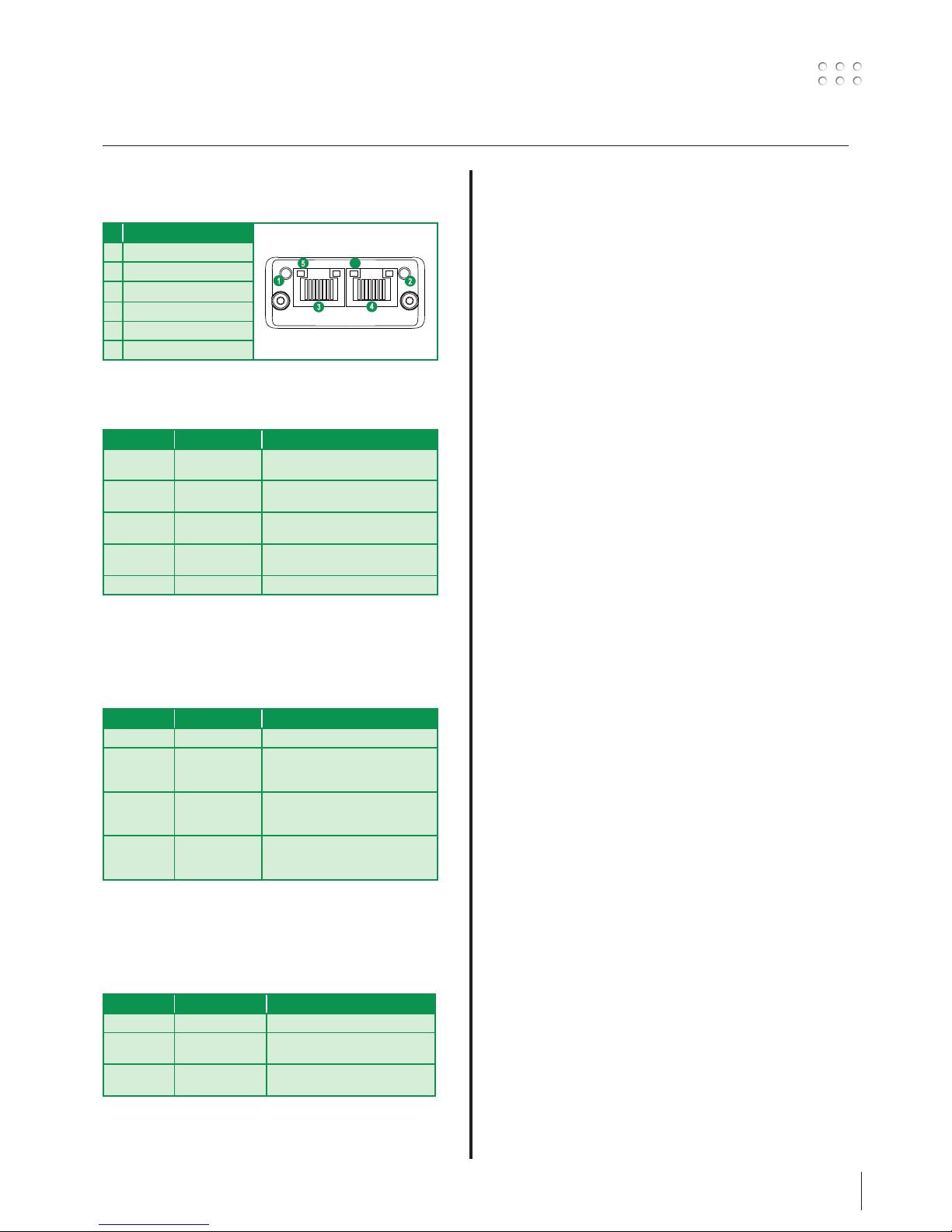
Anybus indicators
EtherNet IP
# Item
1 Network status LED
2 Module status LED
3 Link/Activity
4 Ethernet Interface
Network Status LED
LED State Description
Off No power or no IP address
Green On-line, one or more connections
established (CIP Class 1 or 3)
Green, flashing On-line, no connections established
Red Duplicate IP address, FATAL error
Red, flashing One or more connections timed out (CIP
Class 1 or 3)
Module Status LED
Note: A test sequence is performed on this LED during
startup
LED State Description
Off No power
Green Controlled by a Scanner in Run state
Green, flashing Not configured, or Scanner in Idle state
Red Major fault (EXCEPTION-state, FATAL
error etc.)
Red, flashing Recoverable Fault(s)
LINK/Activity LED
LED State Description
Off No link, no activity
Green Link established
Green, flickering Activity
1
8
DeviceNet
# Item
1 Network status LED
2 Module status LED
3 DeviceNet connector
4 M12 Female connector
5 M12 Male connector
Network Status
State Indication
Off Not online / No power
Green On-line, one or more connections are
established
Flashing Green (1 Hz) On-line, no connections established
Red Critical link failure
Flashing Red (1 Hz) One or more connections timed-out
Alternating
Red/Green
Self test
Module Status
State Indication
Off No power
Green Operating in normal condition
Flashing Green (1 Hz) Missing or incomplete configuration,
device needs commissioning
Red Unrecoverable Fault(s)
Flashing Red (1 Hz) Recoverable Fault(s)
Alternating
Red/Green
Self test
DeviceNet Connector
This connector provides DeviceNet connectivity
Pin Signal Description
1 V- Negative bus supply voltage
2 CAN_L CAN low bus line
3 SHIELD Cable shield
4 CAN_H CAN high bus line
5 V+ Positive bus supply voltage
28
Anybus indicators
PROFIBUS
# Item
1 Operation Mode
2 Status
3 PROFIBUS Connector
4 M12 Female Connector
5 M12 Male connector
Operation Mode
State Indication
Off Not online / No power
Green Data exchange
Flashing Green Clear
Flashing Red (1 flash) Parametrization error
Flashing Red (2 flashes) PROFIBUS Configuration error
Status
State Indication Comments
Off Not initialized Anybus state = ‘SETUP¨’ or
‘NW_INIT’
Green Initialized Anybus module has left the
‘NW_INIT’ state
Flashing Green Initialized, diagnostic
event(s) present
Extended diagnostic bit is set
Red Exception error Anybus state = ‘EXCEPTION’
ProfiNet IP
# Item
1 Network status LED
2 Module status LED
3 Link/Activity LED
4 Ethernet Interface
Network Status LED
Note: A test sequence is performed on this LED during
startup
LED State Description Comments
Off Offline - No power
- No connection with IO Controller
Green Online
(RUN)
- Connection with IO Controller
established
- IO Controller in RUN state
Green,
flashing
Online
(STOP)
- Connection with IO Controller
established
- IO Controller in STOP state
Module Status LED
Note: A test sequence is performed on this LED during
startup
LED State Description Comments
Off Not Initialized No power - or - Module in ‘SETUP’
or ‘NW_INIT’ state
Green Normal
Operation
Module has shifted from the
‘NW_INIT’ state
Green,
1 flash
Diagnostic
Event(s)
Diagnostic event(s) present
Green,
2 flashes
Blink Used by engineering tools to
identify the node on the network
Red Exception Error Module in state ‘EXCEPTION’
Red, 1 flash Configuration
Error
Expected Identification differs
from Real Identification
Red,
2 flashes
IP Address Error IP address not set
Red,
3 flashes
Station Name
Error
Station Name not set
Red,
4 flashes
Internal Error Module has encountered a major
internal error
LINK/Activity LED
LED State Description Comments
Off No link No link, no communication present
Green Link Ethernet link established, no
communication present
Green,
flickering
Activity Ethernet link established,
communication present
Ethernet Interface
The Ethernet interface operates at 100 Mbit, full duplex,
with autonegotiation enabled as default.
1
8
29
Anybus indicators
EtherCAT
EtherCAT Connector
# Item
1 RUN LED
2 ERROR LED
3 EtherCAT (port 1)
4 EtherCAT (port 2)
5 Link/Activity (port 1)
6 Link/Activity (port 2)
RUN LED
This LED reflects the status of the CoE (CANopen over EtherCAT)
communication
LED State Indication Description
Off INIT CoE device in
‘INIT’-state (or no power)
Green OPERATIONAL CoE device in
‘OPERATIONAL’-state
Green,
blinking
PREOPERATIONAL
CoE device in
‘PRE-OPERATIONAL’-state
Green,
single flash
SAFEOPERATIONAL
CoE device in
‘SAFE-OPERATIONAL’-state
Red
a
(Fatal Event) -
a. If RUN and ERR turns red, this indicates a fatal event,
forcing the bus interface to a physically passive state.
Contact HMS technical support
ERR LED
This LED indicates EtherCAT communication errors etc.
LED State Indication Description
Off No error No error (or no power)
Red,
blinking
Invalid
configuration
State change received from
master is not possible due to
invalid register or object settings
Red,
double flash
Application
watchdog
timeout
Sync manager watchdog timeout
Red
a
Application
controller
failure
Anybus module in EXCEPTION
a. If RUN and ERR turns red, this indicates a fatal event,
forcing the bus interface to a physically passive state.
Contact HMS technical support
LINK/Activity
These LEDs indicate the EtherCAT link status and activity
LED State Indication Description
Off No link Link not sensed (or no power)
Green Link sensed, no
activity
Link sensed, no traffic detected
Green,
flickering
Link sensed,
activity detected
Link sensed, traffic detected
6

30
 Loading...