

Migatronic SIGMA ROBO User Manual

BRUGSVEJLEDNING
USER GUIDE
BETRIEBSANLEITUNG
GUIDE DE L’UTILISATEUR
BRUKSANVISNING
GUIDA PER L’UTILIZZATORE
GEBRUIKERSHANDLEIDING
KÄYTTÖOHJE
GUÍA DE USUARIO
KEZELÉSI ÚTMUTATÓ
PODRĘCZNIK UŻYTKOWNIKA
РУКОВОДСТВО ПОЛЬЗОВАТЕЛЯ
SIGMA ROBO
50115022 B1 Valid from 2017 week 20

2
Dansk ..................................................................3
English ..............................................................11
Deutsch ............................................................. 19
Français ............................................................. 27
Svenska ............................................................. 35
Italiano .............................................................43
Nederlands .......................................................51
Suomi ................................................................ 59
Español .............................................................67
Magyar ..............................................................75
Polski .................................................................83
Русский ...........................................................91
3
Tilslutning og ibrugtagning
Advarsel
Læs advarsel og brugsanvisning omhyggeligt
igennem inden installation
og ibrugtagning og gem til
senere brug.
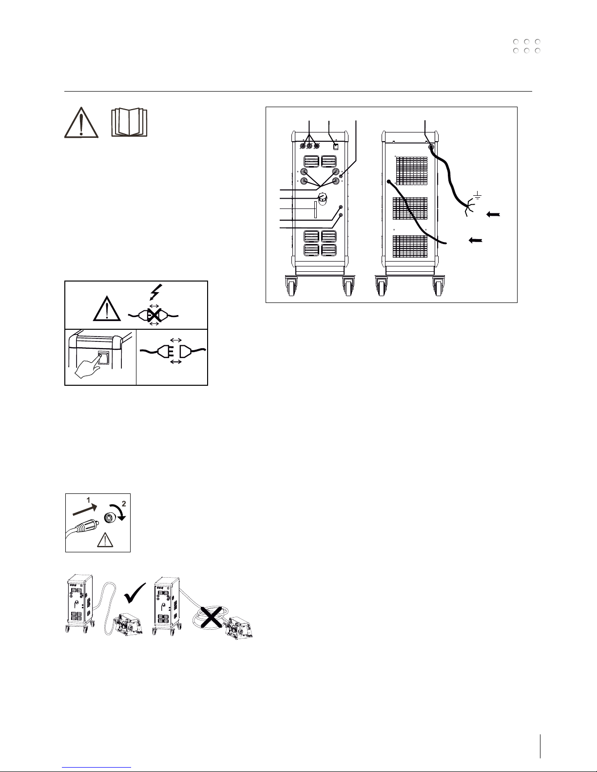
Installation
Nettilslutning
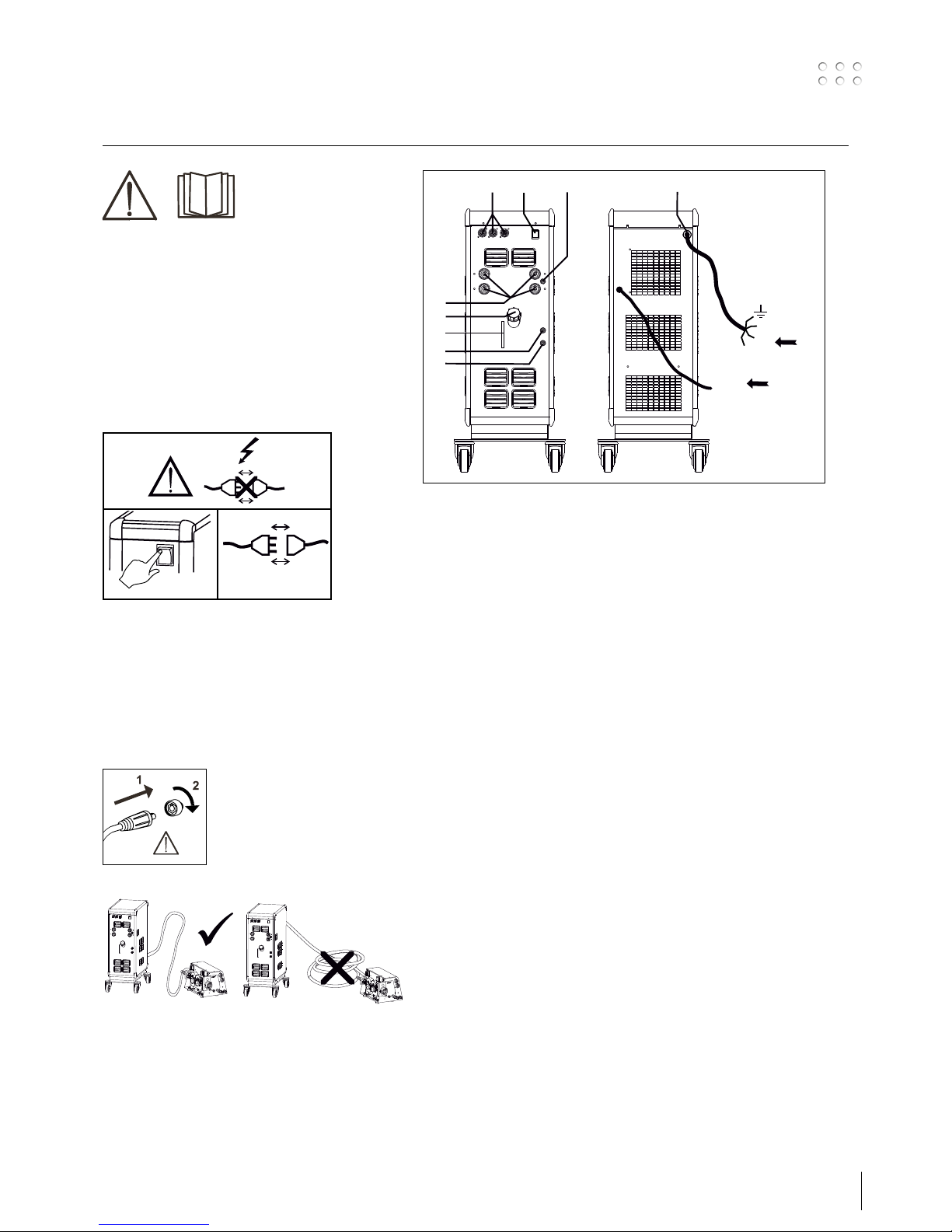
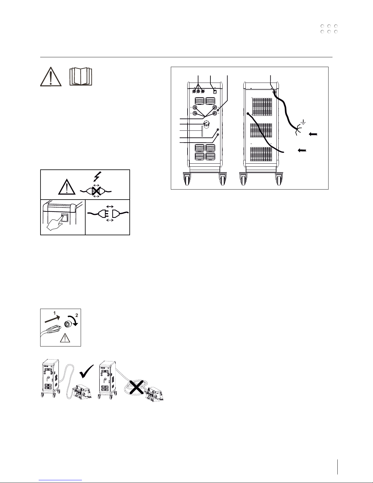
Tilslut maskinen til den netspænding den er
konstrueret til. Se typeskiltet (U1) bag på maskinen.
0
l
1
2
Tilslutning af beskyttelsesgas
Gasslangen, som udgår fra bagsiden af maskinen,
tilsluttes en gasforsyning med en reduktionsventil
(2-6bar). (Obs. Nogle typer reduktionsventiler kan
kræve højere udgangstryk end 2 bar for at fungere
optimalt).
En/to gasflasker kan fikseres bag på vognen.
Vigtigt!
Når stelkabel og svejseslange
tilsluttes maskinen, er god elektrisk
kontakt nødvendig, for at undgå at
stik og kabler ødelægges.
Tilslutning af elektrodeholder for MMA
Elektrodeholder og stelkabel tilsluttes plusudtag
og minusudtag. Polariteten vælges efter elektrodeleverandørens anvisning.
1. Nettilslutning
2. Tænd – sluk knap
3. Tilslutning beskyttelsesgas
4. Tilslutning køleslanger
5. Tilslutning køleslanger
6. Stelklemme (MIG) eller elektrodeholdertilslutning
7. Aflæsning af kølevæskestand
8. Påfyldning af kølevæske
9. Tilslutning Remote
2
/RWF2
Power
GAS
2-6 bar
1
3
F
F
F
2
9
4
5
6
7
8
4
Tilslutning og ibrugtagning
Tænd, tryk, svejs
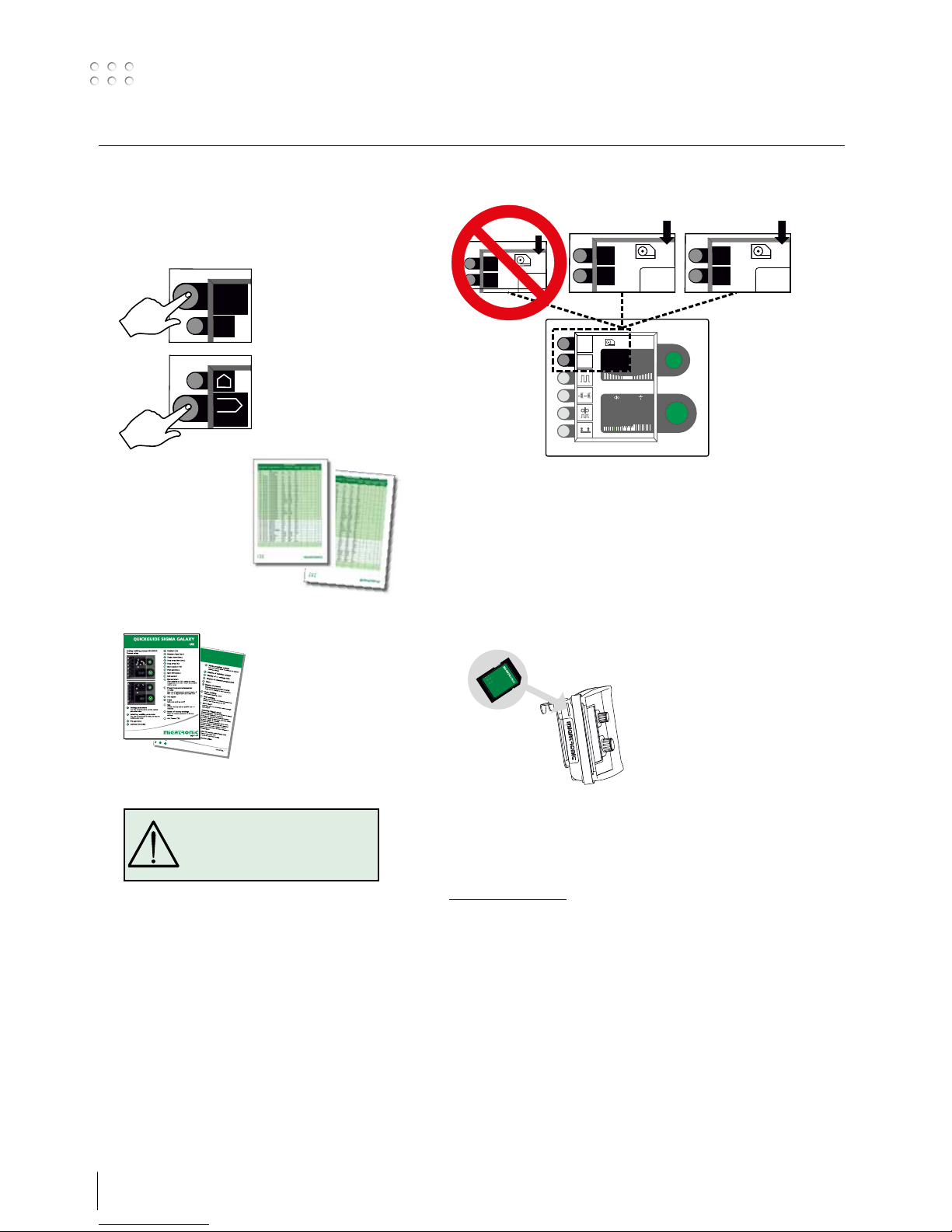
Indstilling af svejseprogram.
• Tænd svejsemaskinen på hovedafbryderen (2)
• Vælg svejseprogram
Se i Quickguide hvordan
det vælges for din
svejsemaskine. Vælg
det svejseprogram, som
passer til den svejsetråd
og beskyttelsesgas eller
evt. elektrode, der skal
svejses med.
Se programliste
• Indstil svejsestrøm og sekundære parametre
Se Quickguide
• Maskinen er nu klar til at svejse
MENU
9
/9
#
1
2
PROG
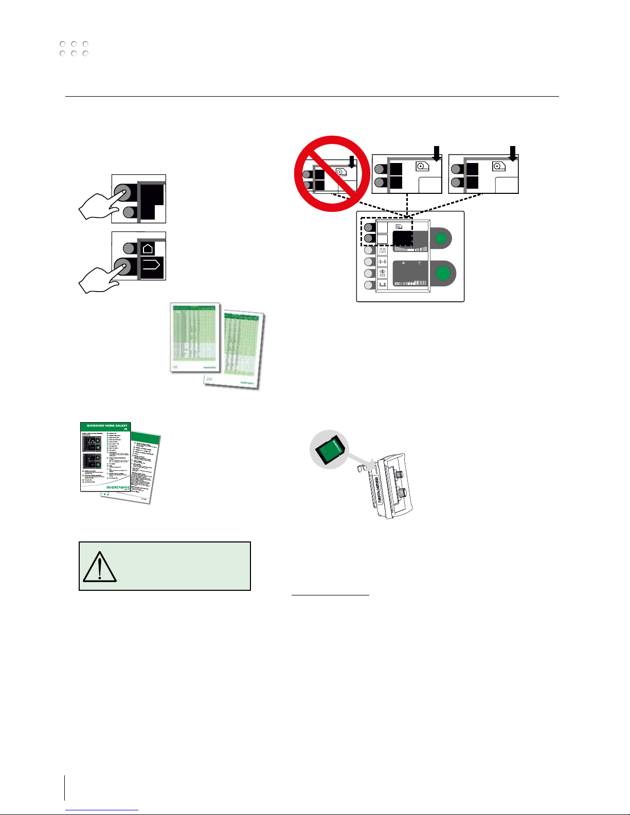
Flere trådbokse
Software indlæsning
• Isæt SD-kort
• Tænd maskinen
• Vent indtil lysdioden på fronten af
RWF
2
-enheden begynder at blinke
• Sluk maskinen og tag SD-kortet ud
• Maskinen er nu klar til brug.
Alle trådbokse, strømkilde og RCI
2
som er tilkoblet
får indlæst den nye software.
Softwaren kan downloades fra
www.migatronic.com
Licens SW
Ved tilkøb af ekstralicenser til programmer eller
særlige funktioner skal MigaLic.dat filerne indlæses
på samme vis som SW-pakker. Husk at gemme en
sikkerhedskopi af filerne.
MigaLic.txt filen indeholder information om licensnummer og de gemte licenser på SD-kort.
MENU
9
/9
#
i
15.
0.0
MENU
9
/9
#
1
15.
0.0
MENU
9
/9
#
2
15.
0.0
RWF² 1 RWF² 2
MENU
9
/9
#
1
15.0V
125A
0.0 V
6.2 m/min 5.0 mm
ADVARSEL
Når der trykkes på svejseslangens
kontakt/tast er der spænding på
svejsetråden.

5
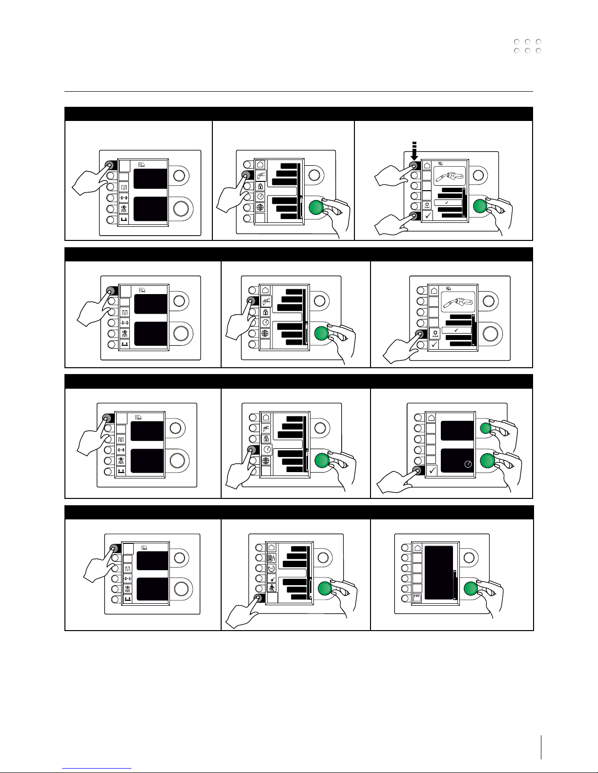
Specielle funktioner
Visning af softwareversioner/licensnr.
I
MENU
9
/9
#
i
1
II
Job
Service
Statistic
Processsetup
Lic
?
2
1
III
Software versions
SD
Licenceno.:
000004D21234
Weldingpackage:
(10645900) A7
Wirefeeder :
(10001341) 2.07
Powermodule 400A:
(10001703) 7.01
MIG manager:
(10060001) 4.31
1
Indstilling af tid
I
MENU
9
/9
#
i
1
II
Process setup
Job
Machine setup
Statistic
1
2
III
Hour Min
Sec
Day
Month Year
13 21
00
06 05
2010
Hour
0
1
2
Til-/frakobling af vandkøling (MIG/MAG)
I
MENU
9
/9
#
i
1
II
Process setup
Job
Machine setup
Statistic
2
1
III
Dialog
Standard /OFF
i
Analog remote
Mig manager
Konfiguration af intern/ekstern kontrol
I
MENU
9
/9
#
i
1
II
Process setup
Job
Machine setup
Statistic
2
1
III
Dialog
Standard /OFF
i
Analog remote
Mig manager
2
1
3
x2

6
Specielle funktioner
Sprogvalg
I
MENU
9
/9
#
i
1
II
Process setup
Job
Machine setup
Statistic
Wire feedersel.
2
1
III
English
Deutsch
Polski
Dansk
1
2
Visning af licensoversigt
I
MENU
9
/9
#
i
1
II
Job
Service
Statistic
Processsetup
Lic
?
1
2
III
Licence
Lic.: 000004D21234
Licences total:83
P001 P004
P101 P102 P103 P104
P106 P109 P111 P112
P113 P114 P116 P117
P118 P119 P120 P121
P122 P123 P125 P126
P127 P128 P132 P133
P152 P153 P157 P163
Gold card:5666 min.
Statistics:Yes
1
Låsefunktion (option)
I
MENU
9
/9
#
i
1
II
Process setup
Job
Machine setup
Statistic
2
1
III
Functions locked
Level 2
Level 3
Level 1
MENU
DUO plus
Pulse welding
2
1

7
Specielle funktioner
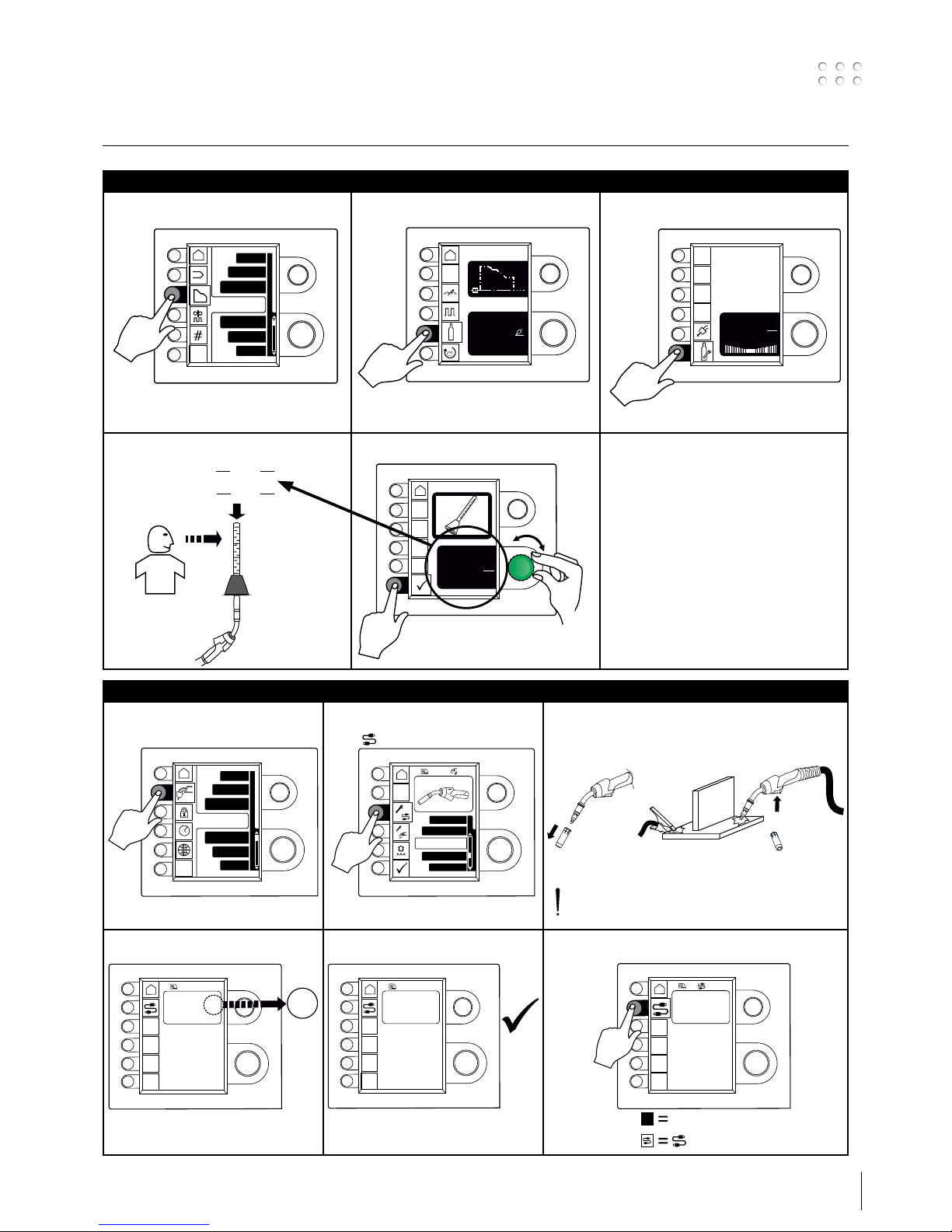
Kalibrering af gasflow
I II III
IV V
Job
Statistic
Process setup
Service
Machine setup
PROG
0.0
Pre gas
Set current:
A
125
S
t1
IGC
Gas flow - IGC
0.5
min
L
0 %
Set current:
A
125
min
L
10
=
20
=
min
L
min
L
10
20
min
L
-0.3
min
L
Flow: 10 l/min
1
2
Kabelkompensering (kalibrering af modstand i svejseslange)
I
Process setup
Job
Machine setup
Statistic
Wire feedersel.
II
MIG-ATWIST
V2 (Nov. 2010)
i
Factor
III
1
2
IV
i
Cable compensation
Factor:
Compensation: Off
- - -
- - -
V
i
Cable compensation
Factor:
Compensation: Off
12.3
VI
Std.
i
Cable compensation
Factor:
Compensation: On
12.3
Svejseemnets overflade skal være ren for
at sikre god kontakt med brænderen.
8
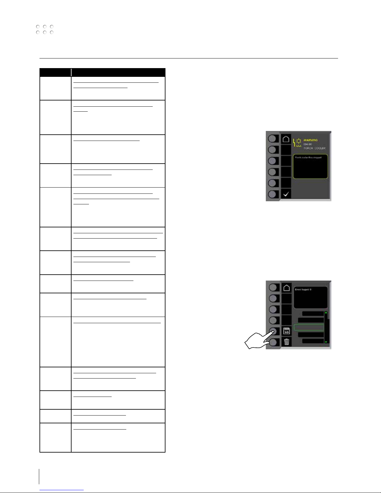
Fejlhåndtering
SIGMA Galaxy har et avanceret selvbeskyttelsessystem indbygget. Ved
fejl lukker maskinen automatisk for gastilførslen, afbryder svejsestrømmen og stopper trådfremførelsen.
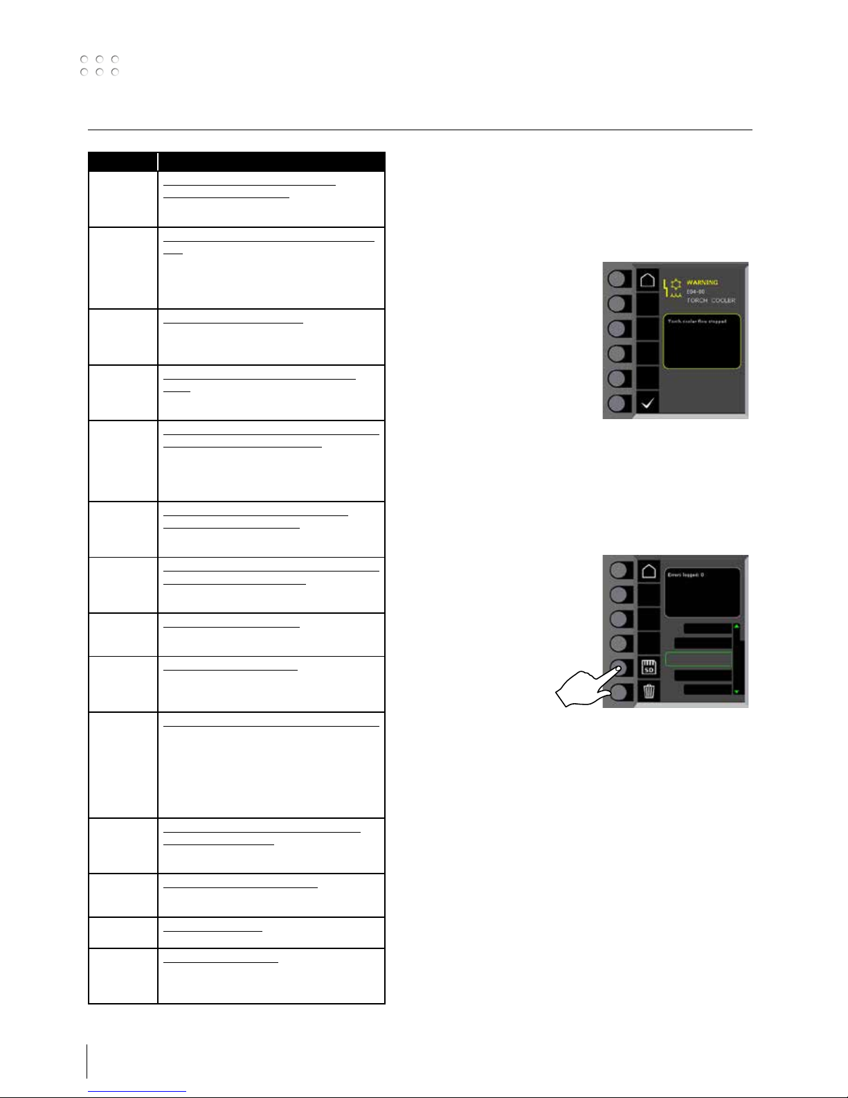
Udvalgte fejl:
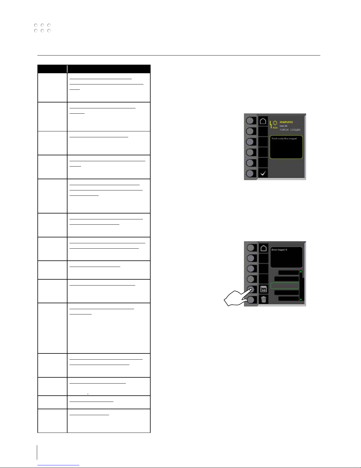
Kølefejl
Kølefejl vises på maskiner med
monteret vandflowkit, i tilfælde af at
kølevandet ikke kan cirkulere som følge
af forkert tilslutning eller tilstopning.
Kontroller at køleslangerne er korrekt
tilsluttet, efterfyld vandbeholderen og
efterse svejseslange og tilslutningsstudser. Kølefejlen afmeldes med et kort
tryk på P-knappen
Gasfejl
Gasfejl kan skyldes for lavt eller for højt tryk på gastilførslen.
Kontroller at trykket på gastilførslen er højere end 2 bar og mindre end
6 bar, svarende til 5 l/min og 27 l/min.
Gasfejl kan sættes ud af funktion ved at indstille manuel gasflow til
27l/min. Gasfejlen afmeldes med et kort tryk på P-knappen.
Fejllog
Alle fejl gemmes i maskinens fejllog
under menuen Service.
Fejlloggen kan distribueres, når der
indsættes et SD-kort og trykkes på
følgende tast:
Fejlloggen er nu gemt på SD-kortet.
Fejlloggen kan nulstilles, når der trykkes
på tasten ud for skraldespanden.
Fejlfinding og udbedring
Fejlkode Årsag og udbedring
E13-03 Det er ikke muligt at aktivere
DuoPlus, mens Sequence Repeat er
aktiv
Slå Sequence Repeat fra, før du
aktiverer DuoPlus.
E20-00
E20-02
E21-00
E21-06
E21-08
Der er ingen software i kontrolboksen
Download software til SD kortet, sæt
SD kortet i boksen og tænd maskinen. Udskift evt. SD kortet.
E20-01
E21-01
E22-02
SD kortet er ikke formateret
Formater SD kortet i en PC som FAT
og download software til SD kortet.
Udskift evt. SD kortet.
E20-03
E21-02
E22-08
SD kortet har flere filer med samme
navn
Slet SD kortet og download software
igen.
E20-04 Kontrolboksen har forsøgt at ind-
læse flere data end den kan have i
hukommelsen
Indlæs SD kortet igen eller udskift SD
kortet. Tilkald MIGATRONIC Service,
hvis problemet ikke løses.
E20-05
E20-06
E22-03
Software på SD kortet er låst til en
anden type kontrolboks
Anvend et SD kort med software som
passer til din type kontrolboks.
E20-07 Den interne kopibeskyttelse tillader
ikke adgang til mikroprocessoren
Indlæs SD kortet i maskinen igen eller
tilkald MIGATRONIC Service.
E20-08
E20-09
E21-05
Kontrolboksen er defekt
Tilkald MIGATRONIC Service.
E20-10
E21-07
E22-01
E22-06
Den indlæste fil er fejlbehæftet
Indlæs SD kortet igen eller udskift SD
kortet.
E20-11 Manglende kommunikation til
strømkilde
Skift mellemkabel, hvis dette er
beskadiget. Tjek at strømkilde og
trådboks passer sammen (MK1/MK1
eller MK2/MK2).
Hvis problemet ikke er løst indlæs da
SD kortet igen eller tilkald
MIGATRONIC Service.
E21-03
E21-04
Den indlæste svejseprogrampakke
passer ikke til kontrolboksen
Anvend et SD kort med software som
passer til din kontrolboks.
E21-09 For lidt intern hukommelse
Svejseprogrampakke kan ikke
indlæses.
E22-04
E22-07
DSP-printet er defekt
Tilkald MIGATRONIC Service
E22-05 Dataoverførselsfejl
Sluk og tænd maskinen. Udskift SD
kortet, hvis fejlen vedbliver.
Kontakt evt. forhandleren
9
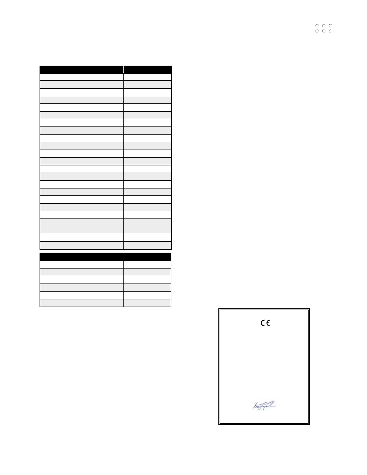
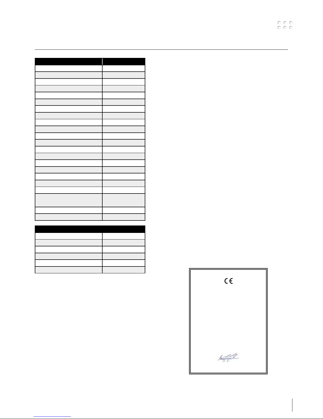
STRØMKILDE SIGMA ROBO
Netspænding ±15% (50-60Hz), V 3x400
Minimum generatorstørrelse, kVA 36
Sikring, A 32
Netstrøm, effektiv, A 29,3 (380V)/27,8 (400V)
Netstrøm, max., A 36,8 (380V)/35,0 (400V)
Effekt, 100%, kVA 17,9
Effekt, max., kVA 24,2
Effekt, tomgang, VA 40
Virkningsgrad 0,90
Effektfaktor 0,90
Strømområde, A 15-500
Intermittens, 100% 20°C (MIG), A/V 475/37,8
Intermittens, maks. 20°C (MIG), A/%/V 500/80/39,0
Intermittens, 100% 40°C (MIG), A/V 420/35,0
Intermittens, 60% 40°C (MIG), A/V 450/36,5
Intermittens, maks. 40°C (MIG), A/%/V 500/55/39,0
Tomgangsspænding, V 78-95
1)
Anvendelsesklasse S/CE/CCC
2)
Beskyttelsesklasse IP23S
Normer EN/IEC60974-1,
EN/IEC60974-2,
EN/IEC60974-10
Dimensioner (HxBxL), mm 1092 x 614 x 410
Vægt, kg 71
1) Maskiner opfylder de krav der stilles under anvendelse i områder med forøget risiko for elektrisk chok
2) Angiver at maskinen er beregnet for såvel indendørs som udendørs anvendelse
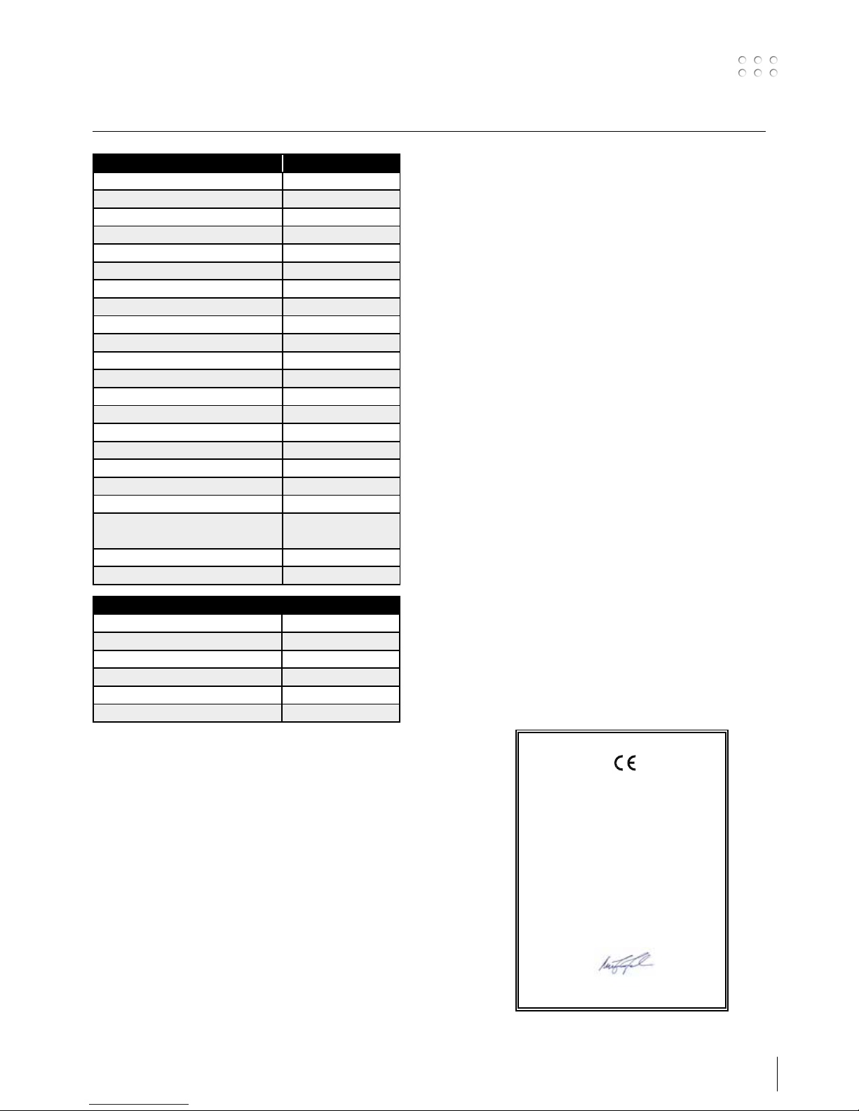
EU-OVERENSSTEMMELSESERKLÆRING
MIGATRONIC A/S
Aggersundvej 33
9690 Fjerritslev
Danmark
erklærer, at nedennævnte maskine
Type: SIGMA ROBO
er i overensstemmelse med bestemmelserne i
direktiverne 2014/35/EU
2014/30/EU
2011/65/EU
Europæiske EN/IEC60974-1
standarder: EN/IEC60974-2
EN/IEC60974-10 (Class A)
Udfærdiget i Fjerritslev 17.05.2017
Niels Jørn Jakobsen
CEO
Tekniske data
KØLEMODUL
Kølekapacitet (1 l/min), W 1650
Kølekapacitet (1,5 l/min), W 1900
Tankkapacitet, liter 3,5
Flow, bar - °C - l/min 3,0 - 60 - 1,5
Maks. tryk, bar 4,5
Normer EN/IEC60974-2

10
11
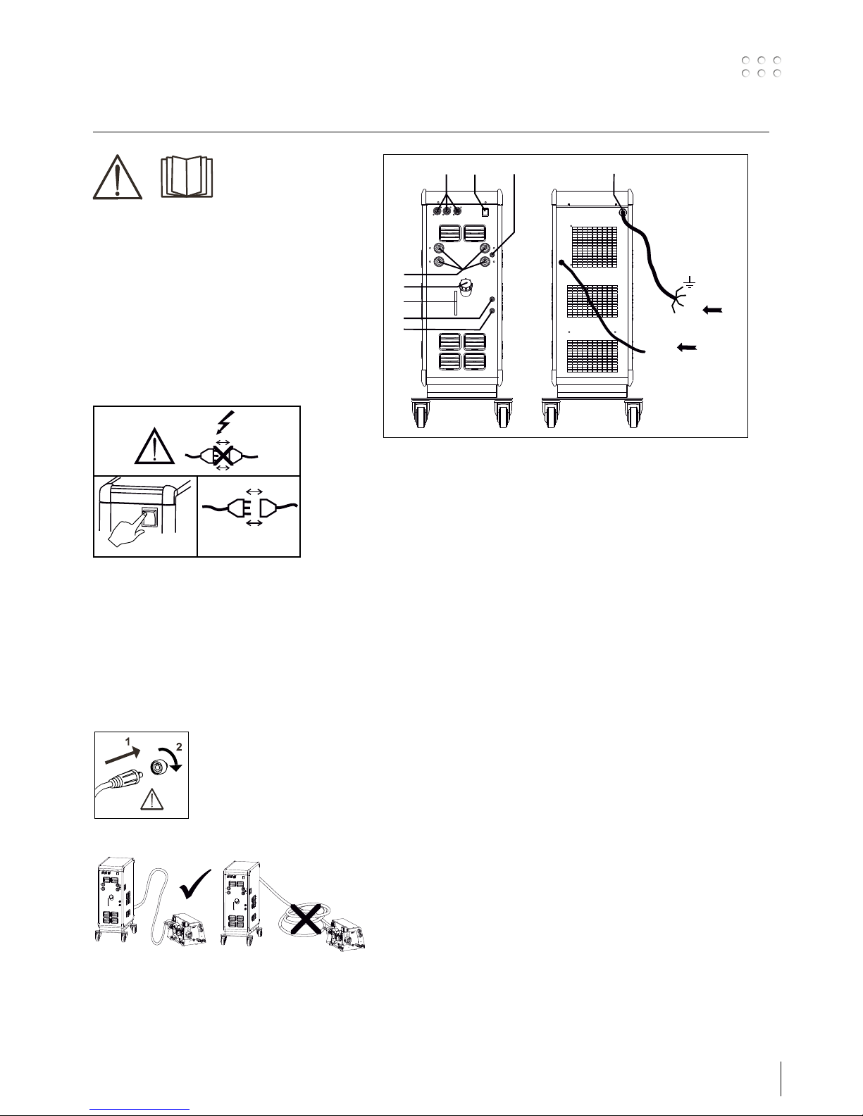
Connection and operation
Warning
Read warning notice and
instruction manual carefully
prior to initial operation and
save the information for later
use.
Permissible installation
Mains connection
Connect the machine to the correct mains supply. Please
read the type plate (U1) on the rear side of the machine.
0
l
1
2
Connection of shielding gas
Connect the gas hose, which branches off from the
back panel of the welding machine, to a gas supply
with pressure regulator (2-6 bar). (Note: Some types of
pressure regulators require an output pressure of more
than 2 bar to function optimally).
One/two gas cylinders can be mounted on the bottle
carrier on the back of the trolley.
Important!
In order to avoid destruction of plugs
and cables, good electric contact
is required when connecting earth
cables and welding hoses to the
machine.
Connection of electrode holder for MMA
The electrode holder and earth cable are connected
to plus connection and minus connection. Observe the
instructions from the electrode supplier when selecting
polarity.
1. Mains connection
2. Power switch
3. Connection of shielding gas
4. Connection of cooling hoses
5. Connection of cooling hoses
6. Connection of earth clamp (MIG) or electrode holder
7. Cooling liquid level control
8. Refill of cooling liquid
9. Connection Remote
2
/RWF2
Power
GAS
2-6 bar
1
3
F
F
F
2
9
4
5
6
7
8
12
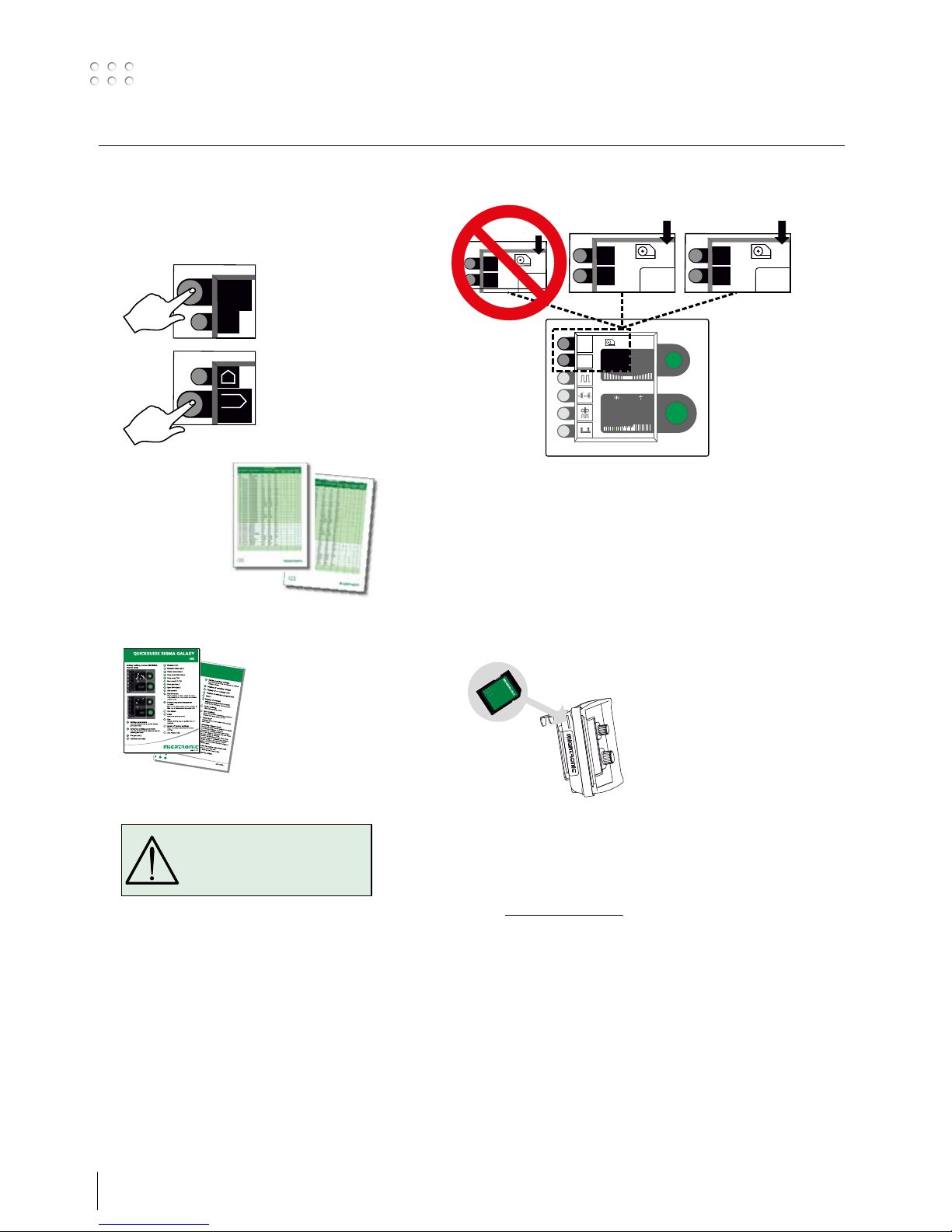
Connection and operation
Switch on, press, weld
Welding program setting.
• Switch on the welding machine on the main switch (2)
• Select welding program
Please read how this
should be selected on your
welding machine in the
quick guide. Select the
welding program suitable
for the welding wire and
shielding gas or possible
electrode in use.
See program table
• Adjust the welding current and secondary parameters
Please read your quickguide
• The machine is now ready to weld
MENU
9
/9
#
1
2
PROG
Various wire feed units
Software reading
• Insert the SD card
• Turn on the machine
• Wait until the LED at the front of the RWF
2
unit
starts flashing
• Turn off the machine and remove the SD card
• The machine is now ready for use
All connected wire feed units, power source and RCI
2
will be updated with the new software.
The software can be downloaded from
www.migatronic.com
Licence SW
If additional licences for programs or special
functions have been bought, then the MigaLic.dat
files should be read by the machine in the same way
as SW-packages. Please remember to save a backup
file.
The MigaLic.txt file contains information about
licence number and containing licences at the SDcard.
WARNING
Voltage is present on the welding
wire when pressing the welding
hose trigger.
MENU
9
/9
#
i
15.
0.0
MENU
9
/9
#
1
15.
0.0
MENU
9
/9
#
2
15.
0.0
RWF² 1 RWF² 2
MENU
9
/9
#
1
15.0V
125A
0.0 V
6.2 m/min 5.0 mm

13
Special functions
Display of software versions/licence number
I
MENU
9
/9
#
i
1
II
Job
Service
Statistic
Processsetup
Lic
?
2
1
III
Software versions
SD
Licenceno.:
000004D21234
Weldingpackage:
(10645900) A7
Wirefeeder :
(10001341) 2.07
Powermodule 400A:
(10001703) 7.01
MIG manager:
(10060001) 4.31
1
Setting of time
I
MENU
9
/9
#
i
1
II
Process setup
Job
Machine setup
Statistic
1
2
III
Hour Min
Sec
Day
Month Year
13 21
00
06 05
2010
Hour
0
1
2
Connection/disconnection of water cooling (MIG/MAG)
I
MENU
9
/9
#
i
1
II
Process setup
Job
Machine setup
Statistic
2
1
III
Dialog
Standard /OFF
i
Analog remote
Mig manager
Configuration of internal/external control
I
MENU
9
/9
#
i
1
II
Process setup
Job
Machine setup
Statistic
2
1
III
Dialog
Standard /OFF
i
Analog remote
Mig manager
2
1
3
x2

14
Special functions
Selecting language
I
MENU
9
/9
#
i
1
II
Process setup
Job
Machine setup
Statistic
Wire feedersel.
2
1
III
English
Deutsch
Polski
Dansk
1
2
Display of licenses
I
MENU
9
/9
#
i
1
II
Job
Service
Statistic
Processsetup
Lic
?
1
2
III
Licence
Lic.: 000004D21234
Licences total:83
P001 P004
P101 P102 P103 P104
P106 P109 P111 P112
P113 P114 P116 P117
P118 P119 P120 P121
P122 P123 P125 P126
P127 P128 P132 P133
P152 P153 P157 P163
Gold card:5666 min.
Statistics:Yes
1
Lock function (Option)
I
MENU
9
/9
#
i
1
II
Process setup
Job
Machine setup
Statistic
2
1
III
Functions locked
Level 2
Level 3
Level 1
MENU
DUO plus
Pulse welding
2
1
15
Special functions
Calibration of gas flow
I II III
IV V
Job
Statistic
Process setup
Service
Machine setup
PROG
0.0
Pre gas
Set current:
A
125
S
t1
IGC
Gas flow - IGC
0.5
min
L
0 %
Set current:
A
125
min
L
10
=
20
=
min
L
min
L
10
20
min
L
-0.3
min
L
Flow: 10 l/min
1
2
Cable compensation (calibration of resistance in welding hose)
I
Process setup
Job
Machine setup
Statistic
Wire feedersel.
II
MIG-ATWIST
V2 (Nov. 2010)
i
Factor
III
1
2
IV
i
Cable compensation
Factor:
Compensation: Off
- - -
- - -
V
i
Cable compensation
Factor:
Compensation: Off
12.3
VI
Std.
i
Cable compensation
Factor:
Compensation: On
12.3
The surface of the workpiece must be clean
to ensure good contact with the torch.
16
Troubleshooting and solution
Error code Cause and solution
E13-03 DuoPlus cannot be activated while
Sequence Repeat is active
Deactivate Sequence Repeat before
activating DuoPlus.
E20-00
E20-02
E21-00
E21-06
E21-08
There is no software present in the control
unit
Download software to the SD card, insert
the SD card in the control unit and turn
on the machine. Replace the SD card if
necessary.
E20-01
E21-01
E22-02
The SD card is not formatted
The SD card must be formatted in a PC as
FAT and download software to the SD card.
Replace the SD card if necessary.
E20-03
E21-02
E22-08
The SD card has more files of the same
name
Delete files on the SD card and reload
software.
E20-04 The control unit has tried to read more data
than is accessible in the memory
Insert the SD card again or replace the SD
card.
Contact MIGATRONIC Service if this does not
solve the problem.
E20-05
E20-06
E22-03
Software on the SD card is locked for
another type of control unit
Use a SD card with software that matches
your control unit.
E20-07 The internal copy protection does not allow
access to the micro-processor
Insert the SD card in the machine again or
contact MIGATRONIC Service.
E20-08
E20-09
E21-05
The control unit is defective
Contact MIGATRONIC Service
E20-10
E21-07
E22-01
E22-06
The loaded file has an error
Insert the SD card in the machine again or
replace the SD card
E20-11 Lacking communication to the power source
Replace the intermediary cable if it is
damaged. Check that power source and
wire feed unit fit together (MK1/MK1 or
MK2/MK2).
If this does not solve the problem, insert
the SD card again or contact MIGATRONIC
Service.
E21-03
E21-04
The welding program package does not
match this control unit
Use a SD card with software that matches
your control unit.
E21-09 The internal memory is to small
Welding program package cannot be
loaded.
E22-04
E22-07
DSP-PCB is defective
Contact MIGATRONIC Service.
E22-05 Data transmission error
Turn on and off the machine. Exchange
the SD card if the error is displayed again.
Contact your dealer if necessary.
Error handling
SIGMA Galaxy has a sophisticated built-in self-protection system. The
machine automatically stops the gas supply, interrupts the welding
current and stops the wire feeding in case of an error.
Selected errors:
Torch cooling fault
Cooling fault is indicated on machines
equipped with water flow kit in case of
no circulation of the cooling liquid due
to faulty connection or choking
Check that the cooling hoses are
correctly connected, top up the water
tank and check welding hose and
branches. The cooling fault is cancelled
by pressing shortly on the P–key pad.
Gas control fault
Gas fault exists due to a to low or high pressure on the gas flow.
Make sure that the pressure on the gas flow is higher than 2 bar and
less than 6 bar, corresponding to 5 l/min and 27 l/min.
The fault is disconnected by adjusting the manual gas flow to 27 l/min.
The gas fault is reset by a short pressure on the P–key pad.
Error log
All errors are saved in the machine error
log in the menu Service. The error log
can be distributed, when inserting a
SD-card and pressing the following key
pad:
The error log is now saved at the SDcard.
The error log can be reset when
pressing the key pad with the
trash bin.
17
Technical data
POWER SOURCE SIGMA ROBO
Mains voltage ±15% (50-60Hz), V 3x400
Minimum generator size, kVA 36
Fuse, A 32
Mains current, effective, A 29.3 (380V)/27.8 (400V)
Mains current, max., A 36.8 (380V)/35.0 (400V)
Power, 100%, kVA 17.9
Power, max., kVA 24.2
Power, open circuit, VA 40
Efficiency 0.90
Power factor 0.90
Current range, A 15-500
Duty cycle, 100% 20°C (MIG), A/V 475/37.8
Duty cycle, max. 20°C (MIG), A/%/V 500/80/39.0
Duty cycle, 100% 40°C (MIG), A/V 420/35.0
Duty cycle, 60% 40°C (MIG), A/V 450/36.5
Duty cycle, max. 40°C (MIG), A/%/V 500/55/39.0
Open circuit voltage, V 78-95
1)
Sphere of application S/CE/CCC
2)
Protection class IP23S
Standards EN/IEC60974-1.
EN/IEC60974-2.
EN/IEC60974-10
Dimensions (HxWxL), mm 1092 x 614 x 410
Weight, kg 71
EC DECLARATION OF CONFORMITY
MIGATRONIC A/S
Aggersundvej 33
9690 Fjerritslev
Denmark
hereby declare that our machine as stated below
Type: SIGMA ROBO
conforms to directives: 2014/35/EU
2014/30/EU
2011/65/EU
European standards: EN/IEC60974-1
EN/IEC60974-2
EN/IEC60974-10 (Class A)
Issued in Fjerritslev 17.05.2017
Niels Jørn Jakobsen
CEO
1) This machine meets the demand made for machines which are to operate in areas with increased hazard of electric chocks.
2) Equipment marked IP23S is designed for indoor and outdoor applications.
COOLING UNIT
Cooling capacity (1.0 l/min), W 1650
Cooling capacity (1.5 l/min), W 1900
Tank capacity, liter 3.5
Flow, bar - °C - l/min 3.0 - 60 - 1.5
Pressure max., bar 4.5
Standards EN/IEC60974-2

18
19
Anschluss und Inbetriebnahme
Warnung
Lesen Sie die Warnhinweise
und Betriebsanleitung
sorgfältig vor der Inbetriebnahme und speichern Sie
die Information für den
späteren Gebrauch.
Zulässige Installation
Netzanschluss
Die Maschine soll an eine Netzspannung angekuppelt
werden, die mit den Angaben auf dem Typenschild
(U1) hinter die Maschine übereinstimmt.
0
l
1
2
Schutzgasanschluss
Den Gasschlauch an der Rückseite der Maschine an eine
Gasversorgung mit Druckregler (2-6 bar) anschließen.
(NB! Einige Druckreglertypen fordern einen hoheren
Ausgangsdruck als 2bar um optimal zu funktionieren).
Eine Gasflasche/zwei Gasflaschen können hinter die
Wagen fixiert werden.
Wichtig!
Achten Sie auf festen Sitz der
Anschlüsse von Massekabel und
Schweißschlauch.
Die Stecker und Kabel können
sonst beschädigt werden.
Anschluss des Elektrodenhalters für MMA
Elektrodenhalter und Massekabel werden an Pluspol und Minuspol angeschlossen. Die zu wählende
Polarität ist von den zu verwendenden Elektroden
abhängig und wird gemäß den Herstellerangaben
(siehe Elektroden-Verpackung) gewählt.
1. Netzanschluss
2. Ein- und Ausschalter
3. Schutzgasanschluss
4. Schnellkupplung für Kühlschlauche
5. Schnellkupplung für Kühlschlauche
6. Anschluß für Masseklemme (MIG) oder
Elektrodenhalter
7. Ablesen von Kühlflüssigstand
8. Nachfüllen von Kühlflüssigkeit
9. Anschluss Remote
2
/RWF2
Power
GAS
2-6 bar
1
3
F
F
F
2
9
4
5
6
7
8

20
Anschluss und Inbetriebnahme
WARNUNG
Spannung ist auf dem Schweißdraht
vorhanden, wenn die Taste des
Schweißschlauchs gedrückt wird.
Einschalten, Drücken, Schweißen
Einstellung des Schweißprograms
• Die Schweißmaschine auf den Hauptschalter (2) einschalten
• Schweißprogramm wählen
Sehen Sie sich die
Quickguide, wie es für
Ihre Schweißmaschine
geltend ist. Wählen
Sie das Programm,
das zum Schweißen
der Schweißdraht und
Schutzgas, eventueller
Elektrode anpasst.
Lesen Sie sich
die Programmliste
• Schweißstrom und sekundäre Parameter einstellen
Bitte Ihre Quickguide
durchlesen
• Die Maschine ist jetzt schweißbereit
MENU
9
/9
#
1
2
PROG
Mehreren Drahtvorschubeinheiten
Software Einlesen
• Die SD-Karte einlegen
• Die Maschine einschalten
• Warten bis die LED an der Vorderseite der RWF
2
-
Einheit zu blinken beginnt
• Die Maschine ausschalten und die SD-Karte
entfernen
• Die Maschine ist nun einsatzbereit.
Neue Software wird in allen angekuppelten Drahtvorschubeinheiten, Stromquelle und RCI
2
eingelesen.
Software kann auf www.migatronic.com eingelest
werden.
Lizenz SW
Wenn mehre Lizenzen für Programme oder Sonderfunktionen erkauft sind, werden die MigaLic.dat
Datei wie die anderen Software-packungen
eingelest. Bitte eine Sicherheitskopie der Software
speichern.
Die MigaLic.txt Datei enthält Information über
lizenznummer und die gespeicherten Lizenzen auf
der SD-Karte.
MENU
9
/9
#
i
15.
0.0
MENU
9
/9
#
1
15.
0.0
MENU
9
/9
#
2
15.
0.0
RWF² 1 RWF² 2
MENU
9
/9
#
1
15.0V
125A
0.0 V
6.2 m/min 5.0 mm
21
Sonderfunktionen
Weisung der Softwareversion/Lizenznummer
I
MENU
9
/9
#
i
1
II
Job
Service
Statistic
Processsetup
Lic
?
2
1
III
Software versions
SD
Licenceno.:
000004D21234
Weldingpackage:
(10645900) A7
Wirefeeder :
(10001341) 2.07
Powermodule 400A:
(10001703) 7.01
MIG manager:
(10060001) 4.31
1
Einstellung der Zeit
I
MENU
9
/9
#
i
1
II
Process setup
Job
Machine setup
Statistic
1
2
III
Hour Min
Sec
Day
Month Year
13 21
00
06 05
2010
Hour
0
1
2
An- und Auskuppelung der Wasserkühlung (MIG/MAG)
I
MENU
9
/9
#
i
1
II
Process setup
Job
Machine setup
Statistic
2
1
III
Dialog
Standard /OFF
i
Analog remote
Mig manager
Konfiguration der interne/externe Regelung
I
MENU
9
/9
#
i
1
II
Process setup
Job
Machine setup
Statistic
2
1
III
Dialog
Standard /OFF
i
Analog remote
Mig manager
2
1
3
x2

22
Sonderfunktionen
Wahl der Sprache
I
MENU
9
/9
#
i
1
II
Process setup
Job
Machine setup
Statistic
Wire feedersel.
2
1
III
English
Deutsch
Polski
Dansk
1
2
Zeigen der Lizenzübersicht
I
MENU
9
/9
#
i
1
II
Job
Service
Statistic
Processsetup
Lic
?
1
2
III
Licence
Lic.: 000004D21234
Licences total:83
P001 P004
P101 P102 P103 P104
P106 P109 P111 P112
P113 P114 P116 P117
P118 P119 P120 P121
P122 P123 P125 P126
P127 P128 P132 P133
P152 P153 P157 P163
Gold card:5666 min.
Statistics:Yes
1
Sperrfunktion (Extra)
I
MENU
9
/9
#
i
1
II
Process setup
Job
Machine setup
Statistic
2
1
III
Functions locked
Level 2
Level 3
Level 1
MENU
DUO plus
Pulse welding
2
1

23
Sonderfunktionen
Kalibrierung des Gasdurchflusses
I II III
IV V
Job
Statistic
Process setup
Service
Machine setup
PROG
0.0
Pre gas
Set current:
A
125
S
t1
IGC
Gas flow - IGC
0.5
min
L
0 %
Set current:
A
125
min
L
10
=
20
=
min
L
min
L
10
20
min
L
-0.3
min
L
Flow: 10 l/min
1
2
Kabelkompensation (Kalibrierung des Widerstandes im Schweißbrenner)
I
Process setup
Job
Machine setup
Statistic
Wire feedersel.
II
MIG-ATWIST
V2 (Nov. 2010)
i
Factor
III
1
2
IV
i
Cable compensation
Factor:
Compensation: Off
- - -
- - -
V
i
Cable compensation
Factor:
Compensation: Off
12.3
VI
Std.
i
Cable compensation
Factor:
Compensation: On
12.3
Die Oberfläche des Werkstücks muss rein
sein zur Sicherstellung des guten Kontakts
mit dem Brenner.
24
Fehlersuche und Ausbesserung
Fehlerhandhabung
SIGMA Galaxy hat ein fortschrittliches Selbstschutz-system. Die
Maschine automatisch stoppt die Gaszufuhr, unterbricht den
Schweißstrom und stoppt die Drahtzuführung, wenn ein Fehler
entsteht.
Ausgewählte Fehler:
Kühlungsfehler
Kühlungsfehler wird angezeigt auf
Geräte mit Wasserdurchflusskit, falls der
Kühlkreislauf unterbrochen oder der
Kühlmitteldurchfluss zu gering ist.
Kontrollieren Sie bitte, dass die
Kühleinheit korrekt angeschlossen
ist und der Wasserbehälter
ausreichend gefüllt ist. Überprüfen
Sie den Schweißbrenner und die
Wasserkühlanschlüsse.
Durch kurzes Drücken auf die P–Taste
wird der Kühlungsfehler abgemeldet.
Gas Fehler
Die Gasmenge ist zu gering oder zu groß.
Kontrollieren Sie bitte, dass die Gaszufuhr höher als 2 bar und weniger
als 6 bar ist, d.h. zwischen 5 l/min und 27 l/min.
Gasfehler wird außer Tätigkeit gesetzt, wenn der manuelle Gasfluß zu
27 l/min eingestellt wird.
Der Gasfehler wird durch kurzen Drücken auf die P–Taste abgemeldet.
Fehlerliste
Alle Fehler sind in der Maschine im
Menü Service gespeichert. Die Fehlerliste kann durch Einsetzen einer SDKarte und Drücken der folgenden Taste
distribuiert werden:
Die Fehlerliste ist dann auf die SD-Karte
gespeichert.
Die Fehlerliste kann durch
Drücken der Taste mit dem
Mülleimer nullgesetzt werden.
Fehlerkodes Ursache und Ausbesserung
E13-03 DuoPlus lässt sich nicht aktivieren, wenn
Sequence Repeat aktiv ist.
Sequence Repeat deaktivieren, bevor Sie
DuoPlus aktivieren.
E20-00
E20-02
E21-00
E21-06
E21-08
Es gibt keine Software in der Kontrolleinheit
Software auf die SD-Karte herunterladen,
die SD-Karte in die Kontrolleinheit einsetzten und die Maschine einschalten. Die
SD-Karte eventuell austauschen.
E20-01
E21-01
E22-02
Die SD-Karte ist nicht formatiert
Die SD-Karte in einem PC als FAT
formatieren und die Software auf die
SD-Karte herunterladen. Die SD-Karte
eventuell austauschen.
E20-03
E21-02
E22-08
Die SD-Karte hat mehrere Dateien mit
demselben Namen
Die SD-Karte leeren und die Software
wieder herunterladen.
E20-04
Die Kontrolleinheit hat versucht mehr
Daten einzulesen als gespeichert werden
können
Die SD-Karte wieder einlesen oder
austauschen. Migatronic Kundenservice
anrufen, wenn das Problem weiterhin
besteht.
E20-05
E20-06
E22-03
Die Software auf der SD-Karte ist für einen
anderen Typ Kontrolleinheit geschlossen
Eine SD-Karte anwenden, deren Software
zu Ihrer Kontrolleinheit passt.
E20-07
Der interne Kopieschutz erlaubt keinen
Zutritt zum Mikroprozessor
Die SD-Karte wieder einlesen oder
Migatronic Kundenservice anrufen.
E20-08
E20-09
E21-05
Die Kontrolleinheit ist defekt
Migatronic Kundenservice anrufen.
E20-10
E21-07
E22-01
E22-06
Die eingelesene Datei ist fehlerhaft
Die SD-Karte wieder einlesen oder
austauschen.
E20-11
Fehlende Kommunikation zur Stromquelle
Das Zwischenschlauchpaket austauschen,
wenn es beschädigt ist. Prüfen, ob
Stromquelle und Drahtvorschubeinheit
zusammen passen (MK1/MK1 oder
MK2/MK2).
Wenn das Problem weiterhin besteht, die
SD-Karte wieder einlesen oder Migatronic
Kundenservice anrufen.
E21-03
E21-04
Das eingelesene Schweißprogrampaket
passt nicht zur Kontrolleinheit
Eine SD-Karte anwenden, deren Software
zu Ihrer Kontrolleinheit passt.
E21-09
Zu wenig Speicher
Das Schweißprogrampaket kann nicht
eingelesen werden.
E22-04
E22-07
Die DSP-Platine ist defekt
Migatronic Kundenservice anrufen.
E22-05
Datenübertragungsfehler
Die Maschine aus- und einschalten. Die
SD-Karte austauschen, wenn der Fehler
weiterhin besteht.
Ihren Händler eventuell kontaktieren.
25
Technische Daten
EU-KONFORMITÄTSERKLÄRUNG
MIGATRONIC A/S
Aggersundvej 33
9690 Fjerritslev
Dänemark
erklärt, dass das unten erwähnte Gerät
Typ: SIGMA ROBO
den Bestimmungen der EU-Richtlinien
2014/35/EU
2014/30/EU
2011/65/EU entspricht
Europäische EN/IEC60974-1
Normen: EN/IEC60974-2
EN/IEC60974-10 (Class A)
Ausgestellt in Fjerritslev am 17.05.2017
Niels Jørn Jakobsen
CEO
1) Erfüllt die Anforderungen an Geräte zur Anwendung unter erhöhter elektrischer Gefährdung
2) Geräte, die der Schutzklasse IP23S entsprechen, sind für den Innen-und Außeneinsatz ausgelegt
STROMQUELLE SIGMA ROBO
Netzspannung ±15% (50-60Hz), V 3x400
Mindestgröße des Generators, kVA 36
Sicherung, A 32
Effektiver Netzstrom, A 29,3 (380V)/27,8 (400V)
Max. Netzstrom, A 36,8 (380V)/35,0 (400V)
Leistung, 100%, kVA 17,9
Leistung, max., kVA 24,2
Leistung, Leerlauf, VA 40
Wirkungsgrad 0,90
Leistungsfaktor 0,90
Strombereich, A 15-500
Zulässige ED, 100% 20°C (MIG), A/V 475/37,8
Zulässige ED, max. 20°C (MIG), A/%/V 500/80/39,0
Zulässige ED, 100% 40°C (MIG), A/V 420/35,0
Zulässige ED, 60% 40°C (MIG), A/V 450/36,5
Zulässige ED, max. 40°C (MIG), A/%/V 500/55/39,0
Leerlaufspannung, V 78-95
1)
Anwendungsklasse S/CE/CCC
2)
Schutzklasse IP23S
Norm EN/IEC60974-1,
EN/IEC60974-2,
EN/IEC60974-10
Maße (HxBxL), mm 1092 x 614 x 410
Gewicht, kg 71
KÜHLEINHEIT
Kühlleistung (1 l/min), W 1650
Kühlleistung (1,5 l/min), W 1900
Tankkapazität, liter 3,5
Durchflussmenge, bar - °C - l/min 3,0 - 60 - 1,5
Druck max., bar 4,5
Norm EN/IEC60974-2

26
27
Branchement et fonctionnement
Attention
Lisez attentivement la fiche
de mise en garde/le mode
d’emploi avant la première
utilisation et conservez ces
informations en vue de leur
utilisation ultérieure.
Installation autorisée
Raccordement électrique
Branchez la machine à une prise secteur adaptée.
Veuillez lire la plaque signalétique (U1) à l’arrière de la
machine.
0
l
1
2
Raccordement au gaz de protection
Raccorder le tuyau de gaz qui se trouve sur le panneau
arrière de la machine et le relier à une alimentation en
gaz avec régulateur de pression (2-6 bars).
(A noter : pour une utilisation optimale certains types
de régulateurs de pression nécessitent une pression de
sortie supérieur à 2 bars).
Une/deux bouteilles de gaz peuvent être installées à
l’arrière du chariot.
Important !
Afin d’éviter la destruction des
prises et câbles, assurez-vous que
le contact électrique est bien établi
lors du branchement des câbles de
mise à la terre et des torches de
soudage à la machine.
Branchement du porte-électrode
pour le soudage MMA
Le porte-électrode et le câble de masse sont branchés
sur la borne plus et la borne moins. Respectez les
instructions relatives à la polarité indiquées par le
fournisseur des électrodes.
1. Raccordement électrique
2. Interrupteur d’alimentation
3. Raccordement au gaz de protection
4. Raccordement des tuyaux du système de
refroidissement
5. Raccordement des tuyaux du système de
refroidissement
6. Raccordement de la pince de mise à la terre (MIG)
ou du porte-électrode
7. Niveau du liquide de refroidissement
8. Remplissage du liquide de refroidissement
9. Raccordement des unités Remote²/RWF²
Power
GAS
2-6 bar
1
3
F
F
F
2
9
4
5
6
7
8
28
Branchement et fonctionnement
Connecter, démarrer, souder
Réglage du programme de soudage
• Démarrer la machine à l’aide de l’interrupteur (2)
• Sélectionner le programme de soudage
Veuillez vous référer
au guide de démarrage
rapide livré avec la
machine. Un programme
de soudage peut être
sélectionné en fonction de
la nuance de fil utilisé, du
gaz de protection ou de
l’électrode.
Voir la table des
programmes
• Ajuster le courant de soudage et les paramètres
secondaires
Veuillez consulter votre guide
rapide
• La machine est désormais prête pour le soudage.
MENU
9
/9
#
1
2
PROG
Utilisation de plusieurs dévidoirs
Lecture Software
• Insérer la carte SD
• Démarrer la machine
• Attendre que le voyant à l’avant du RWF²
clignote
• Eteindre la machine et enlever la carte SD
• La machine est maintenant disponible avec ses
nouveaux softwares
Tous les dévidoirs, source alimentation et RCI²
reliés à la machine seront mis à jour par le nouveau
logiciel.
Vous pouvez télécharger le logiciel à l’adresse
suivante : www.migatronic.com
Licences
En cas d’achat de licences supplémentaires pour des
programmes ou des fonctions spécifiques, les fichiers
MigaLic.dat doivent être lus par la machine de la
même manière que pour les progiciels. Il est alors
important de créer un fichier de sauvegarde.
Le fichier MigaLic.txt contient les informations sur le
numéro de licence et sur les licences de la carte SD.
Attention
L’activation de la gâchette de la
torche génère une tension au
niveau du fil de soudage.
MENU
9
/9
#
i
15.
0.0
MENU
9
/9
#
1
15.
0.0
MENU
9
/9
#
2
15.
0.0
RWF² 1 RWF² 2
MENU
9
/9
#
1
15.0V
125A
0.0 V
6.2 m/min 5.0 mm

29
Fonctions speciales
Affichage de la version du logiciel/du numéro de licence
I
MENU
9
/9
#
i
1
II
Job
Service
Statistic
Processsetup
Lic
?
2
1
III
Software versions
SD
Licenceno.:
000004D21234
Weldingpackage:
(10645900) A7
Wirefeeder :
(10001341) 2.07
Powermodule 400A:
(10001703) 7.01
MIG manager:
(10060001) 4.31
1
Réglage de l’heure
I
MENU
9
/9
#
i
1
II
Process setup
Job
Machine setup
Statistic
1
2
III
Hour Min
Sec
Day
Month Year
13 21
00
06 05
2010
Hour
0
1
2
Mise en route / arrêt du refroidissement de la torche (MIG/MAG)
I
MENU
9
/9
#
i
1
II
Process setup
Job
Machine setup
Statistic
2
1
III
Dialog
Standard /OFF
i
Analog remote
Mig manager
Configuration du réglage interne / externe
I
MENU
9
/9
#
i
1
II
Process setup
Job
Machine setup
Statistic
2
1
III
Dialog
Standard /OFF
i
Analog remote
Mig manager
2
1
3
x2

30
Fonctions speciales
Sélection de la langue
I
MENU
9
/9
#
i
1
II
Process setup
Job
Machine setup
Statistic
Wire feedersel.
2
1
III
English
Deutsch
Polski
Dansk
1
2
Affichage des licences
I
MENU
9
/9
#
i
1
II
Job
Service
Statistic
Processsetup
Lic
?
1
2
III
Licence
Lic.: 000004D21234
Licences total:83
P001 P004
P101 P102 P103 P104
P106 P109 P111 P112
P113 P114 P116 P117
P118 P119 P120 P121
P122 P123 P125 P126
P127 P128 P132 P133
P152 P153 P157 P163
Gold card:5666 min.
Statistics:Yes
1
Fonction de verrouillage (option)
I
MENU
9
/9
#
i
1
II
Process setup
Job
Machine setup
Statistic
2
1
III
Functions locked
Level 2
Level 3
Level 1
MENU
DUO plus
Pulse welding
2
1
 Loading...