

Migatronic RCI2 User Manual
ROBOT CONTROL INTERFACE - RCI
USER GUIDE
2
50115001 C1 Valid from 2019 week 24

Table of contents
Specifications .............................................................................................. 3 - 4
How it works .................................................................................................... 5
Connection to a robot and welding machine ................................................ 6
How to connect the installation ................................................................ 7 - 8
How to do the first configuration and setup ................................................ 9
Jumper settings ............................................................................................. 10
Fieldbus serial communication setup .......................................................... 11
Status menu ............................................................................................ 12 - 14
Setup menu ............................................................................................. 15 - 31
Robot / PLC setup ........................................................................................... 32
Analog Configuration file - PI ................................................................ 33 - 38
Fieldbus Configuration file - PI and PI PLASMA ................................... 39 - 46
Fieldbus Configuration file - PI and PI PLASMA - Std. Motoman ....... 47 - 49
Analog Configuration file - Sigma Galaxy ............................................ 50 - 57
Fieldbus Configuration file - Sigma Galaxy - Standard .......................58 - 60
Fieldbus Configuration file - Sigma Galaxy - Standard Motoman ......61 - 64
Detailed Interface layout .............................................................................. 65
Software upgrade .......................................................................................... 66
Troubleshooting ............................................................................................. 67
Error List .................................................................................................. 68 - 70
ANYBUS - Error List ................................................................................. 71 - 75
Electric Diagram ............................................................................................. 76
SIGMA Robot interface basic setup .............................................................. 77
Spare parts list ............................................................................................... 78
2 3

Specifications
SUPPORTED POWER SOURCES
Migatronic power sources: SIGMA GALAXY with control unit 76113597,
PI 350/500 and PI PLASMA
ANALOG PART OF INTERFACE
ANALOG INPUTS
Galvanic isolated differential inputs: 3
Common mode range: ± 20 VDC
Max differential voltage: 10 VDC
Differential Input impedance: 100K Ohm
Sampling frequency: 100 Hz
Max. pulse frequency (square wave): 10 Hz
Digital resolution: 10 Bit
Error: ± 2 % of reading ± 2 digits(20mV)
ANALOG OUTPUTS
Galvanic isolated differential outputs: 2
Maximum load: 2K Ohm
Output voltage: 0-10 V
Digital resolution: 12 Bit
Sampling frequency: 97 Hz
Error: ± 2 % of reading ± 5 digits(50mV)
Remarks: cannot be used for certification of the welding process
DIGITAL INPUTS
Galvanic isolated inputs: 16
HIGH level (H): 10-26 VDC
LOW level (L): 0-3 VDC
Input impedance: 5K Ohm
Response time to input changes: 100 ms
DIGITAL OUTPUTS
Galvanic isolated outputs: 16
LOW level: 0 V
HIGH level: +20V from internal supply (JMP2 1-2) or
+24V from external supply (JPM2 2-3)
Max load: 50 mA
Response time: 100 ms
GENERAL DATA
Operating temperature: -10 to 40°C (14 to 104°F)

Specifications
FIELDBUS PART OF INTERFACE
Supported Fieldbus communication interface
General Technical Data
Certification UL, cUL File number E214107
CE - Declaration of Pre-Conformity
Emission EN 61000-6-4
EN55011 Radiated emission
EN55011 Conducted emission
Immunity EN 61000-6-2 EN61000-4-2 Electrostatic discharge
EN61000-4-3 Radiated immunity
EN61000-4-4 Fast transients/burst
EN61000-4-5 Surge immunity
EN61000-4-6 Conducted immunity
DeviceNet
Vendor ID / Name: 90 (005Ah) / (HMS Industrial Networks)
Product Name: ‘Anybus-CompactCom DeviceNet’
ProdTypStr: Generic Device
Device Type: 0 (0000h)
Product Code: 98 (0062h) (Anybus-CompactCom DeviceNet)
Baud rates: 125kbps – 250kbps - 500kbps
Major Revision: 2
Minor Revision: 1
The Anybus CompactCom DeviceNet module accepts 11-25 V on the industrial network side of the module. Maximum current
consumption at 11-25 V is 36-38 mA/module.
Ethernet IP
Vendor ID / Name: 90 (005Ah) / (HMS Industrial Networks)
Product Name: ‘Anybus-CC EtherNet/IP’
ProdTypStr: Generic Device
Device Type: 0 (0000h) (Generic Device)
Product Code: 99 (0063h) (Anybus-CompactCom EtherNet/IP)
Assembly instance input: 100 (0064h)
Assembly instance output: 150 (0096h)
Configuration instance: 1 (0001h)
Major Revision: 2 (0002h)
Minor Revision: 11 (000Bh)
The Ethernet interface supports 10/100Mbit, full or half duplex operation.
ProfiNET
Vendor ID: 268 (010Ch) (HMS Industrial Networks)
Device Type: 7 (0007h) (Anybus-CompactCom PROFINET IO)
Station Type: ‘ABCC-PRT’
ProfiBus
IM Manufacturer ID: 268 (010Ch) (HMS Industrial Networks)
IM Order ID: ‘ABCC-DPV1’
IM Profile ID: 62976 (F600h) (Generic Device)
IM Profile Specific Type: 4 (0004h) (Communication Module)
IM Version: 257 (0101h)
IM Supported: 30 (001Eh) (IMO..4 supported)
EtherCAT
Vendor ID E000 001Bha (HMS Industrial Networks Secondary Vendor ID, has to be replaced by Vendor ID of end product vendor.)
a. For firmware revision 1.02 and later.
Product Code 0000 0034h (Anybus CompactCom EtherCAT)
Device Name ‘Anybus-CC EtherCAT’
Serial Number (Assigned during manufacturing)
4 5
How it works
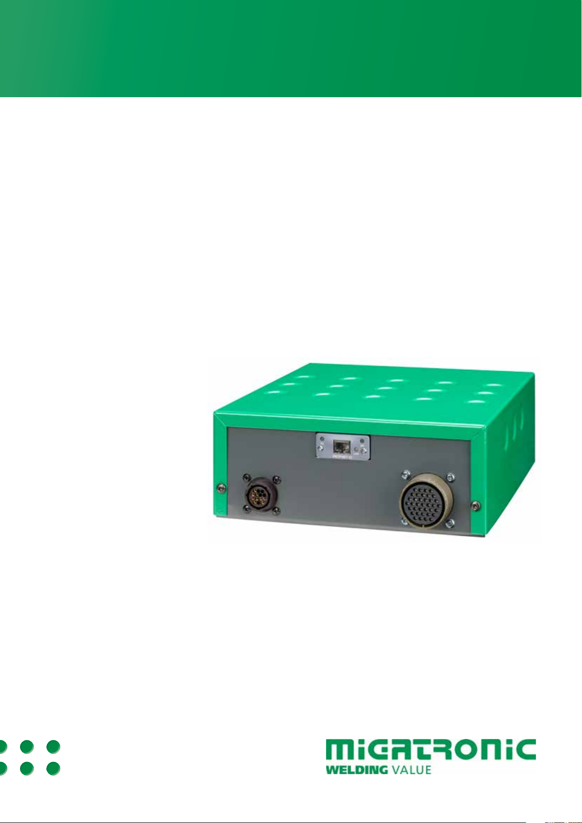
Robot Control Interface (RCI2)
The Robot Control Interface is a flexible I/O
interface system designed for controlling
different Migatronic machines and devices by
means of robots controllers and PLCs.
2
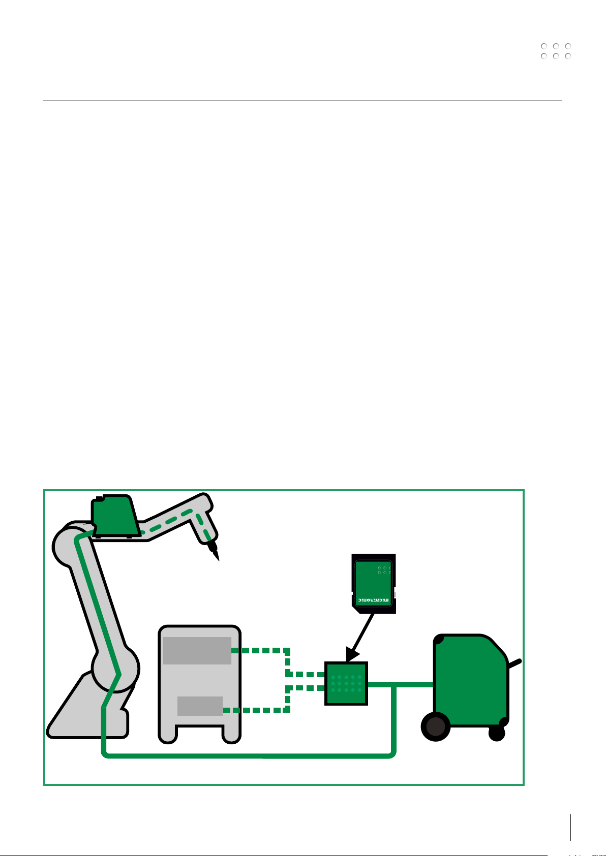
The Robot Control Interface (RCI
) acts as
“translator” between MIGANET and the
connected robot controller.
Interface concept
Several machine parameters like program
selection, secondary functions, internal alarms
etc. are fully accessible, and thus creation
of both sophisticated and simple custom
applications is possible.
There are two possible ways to control the
welding machine, of which only one can be
active at a time:
1: Serial communication:
Serial communication through Fieldbus
and industrial Ethernet via ANYBUS
communication modules. (Referred to as
Fieldbus in the rest of this manual.)
Configuration
2
RCI
has to be setup for the desired way of
communication, by loading a configuration file
directly into RCI2.
There are four different groups of configuration
files.
Pi/Pi Plasma – Analog communication
Pi/Pi Plasma – Fieldbus serial communication
Sigma Galaxy – Analog communication
Sigma Galaxy – Fieldbus serial communication
Each group can contain more configuration files
with special functionality.
See list on page 33-64.
SD card
The SD card contains the configurations files that
are needed by RCI
2
.
It also contains documentation and setup files
that are needed by the robot/PLC controller.
2: Analog communication:
A set of analog inputs and outputs can
control the welding machine.
ROBOT
CONTROLLER
ANALOG/DIGITAL
I/O INTERFACE
PLC
CONFIGURATION
FILE
Analog
communication
MIGANET
(CANBUS)
Fieldbus
communication
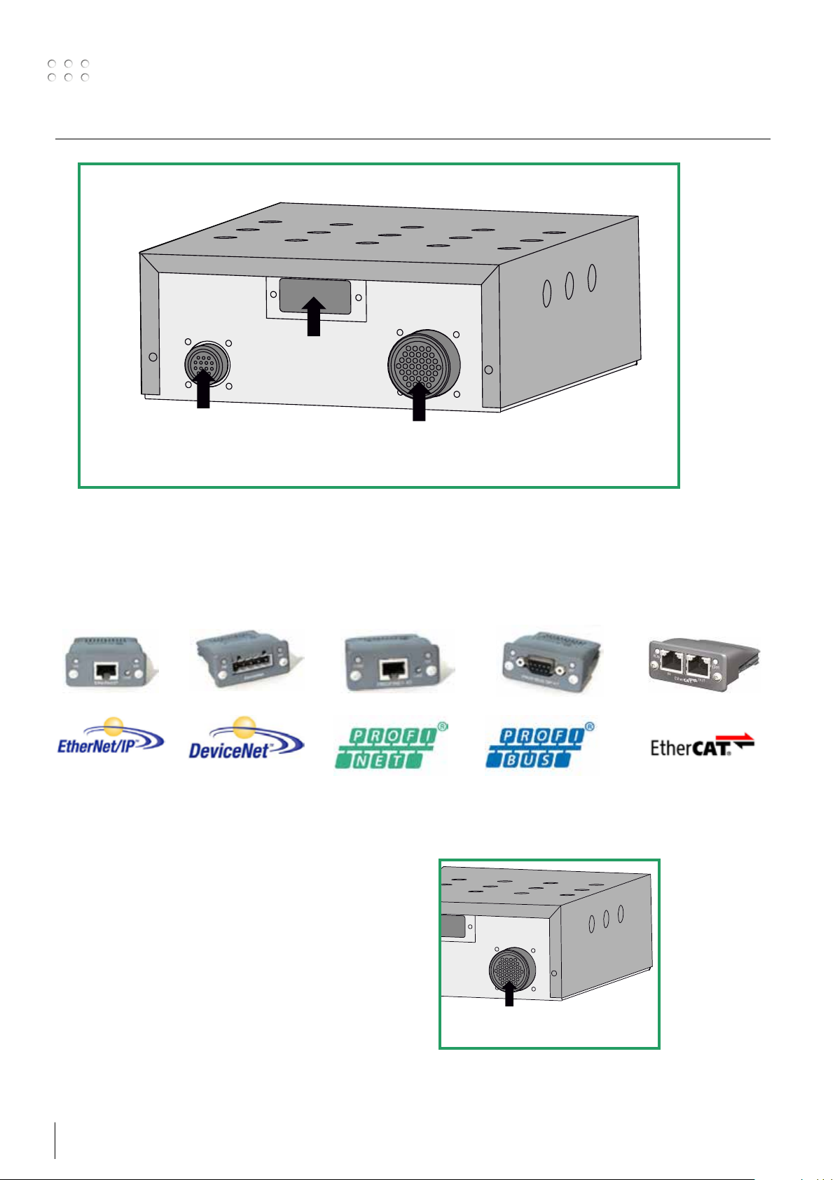
Connection to robot and welding machine
2
RCI
Fieldbus connection
to robot
CANBUS connection
to welding machine
Analog connection
to robot
Fieldbus communication
One of the following Anybus modules is installed when RCI2 is intended for serial communication.
ETHERNET/IP DEVICENET PROFINET PROFIBUS EtherCAT
Analog communication
The analog communication is accessible through
the 37 pin military plug.
The configuration file is defining the function of
each pin.
Setup for analog communication. See page 9
6 7
Analog connection
to robot
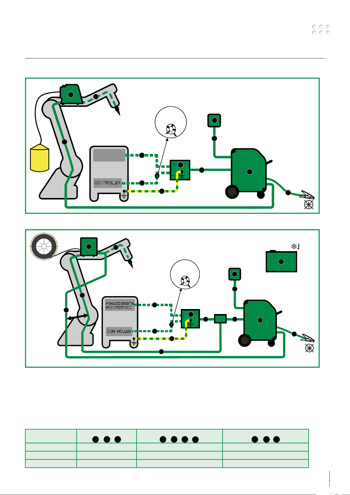
How to connect the installation
MIG installation
RWF²
3
c
TIG installation
CWF²
f
ROBOT / PLC
CONTROLLER
ANALOG/DIGITAL
ANALOG/DIGITAL
I/O INTERFACE
I/O INTERFACE
CONTROLLER
3
f
Analog
communication
1
max. 3 m
Fieldbus
communication
1
3 windings
through core
17440005
e
RCI²
1
3 windings
through core
17440005
REMOTE²
MIGANET
(CANBUS)
b
4
b
SIGMA GALAXY
2
g
EXT. COOLER
REMOTE²
4
6
ROBOT / PLC
CONTROLLER
ANALOG/DIGITAL
ANALOG/DIGITAL
I/O INTERFACE
I/O INTERFACE
CONTROLLER
Note:
Keep distance
of 5 cm
d
h
Main components:
1. Interface - RCI
2
I/O
2. Welding inverter - MIG /TIG/Plasma TIG
3. Wire feed unit - RWF2/CWF
4. Remote2 control
5. CAN connector box
6. Ext. cooler - option for Plasma TIG
Analog
communication
a
max. 3 m
Fieldbus
communication
a
b
RCI²
1
e
CONNECTION
BOX
b
Cables and fittings:
a. Signal cable for robot controller fieldbus or analog
b. CAN communication cable for welding inverter
c. Interconnection, water hose, gas and 2xwelding cable and CAN
d. Highly flexible interconnection for robot
e. Earth connection
f. Welding torch
b
PI & PLASMA TIG
b
2
g. Welding return cable
h. Interconnection, water hose, gas and welding cable
Welding process Distance to work piece
c
( + + )
f
h
Total cable length in welding circuit
c g
( + + + )
f
h
Total length of CAN cable
( + + )
b
MIG – IAC and pulse 10 m 20 m 30 m
MIG – non pulse 30 m 60 m 30 m
TIG 10 m 20 m 30 m
g
c
d
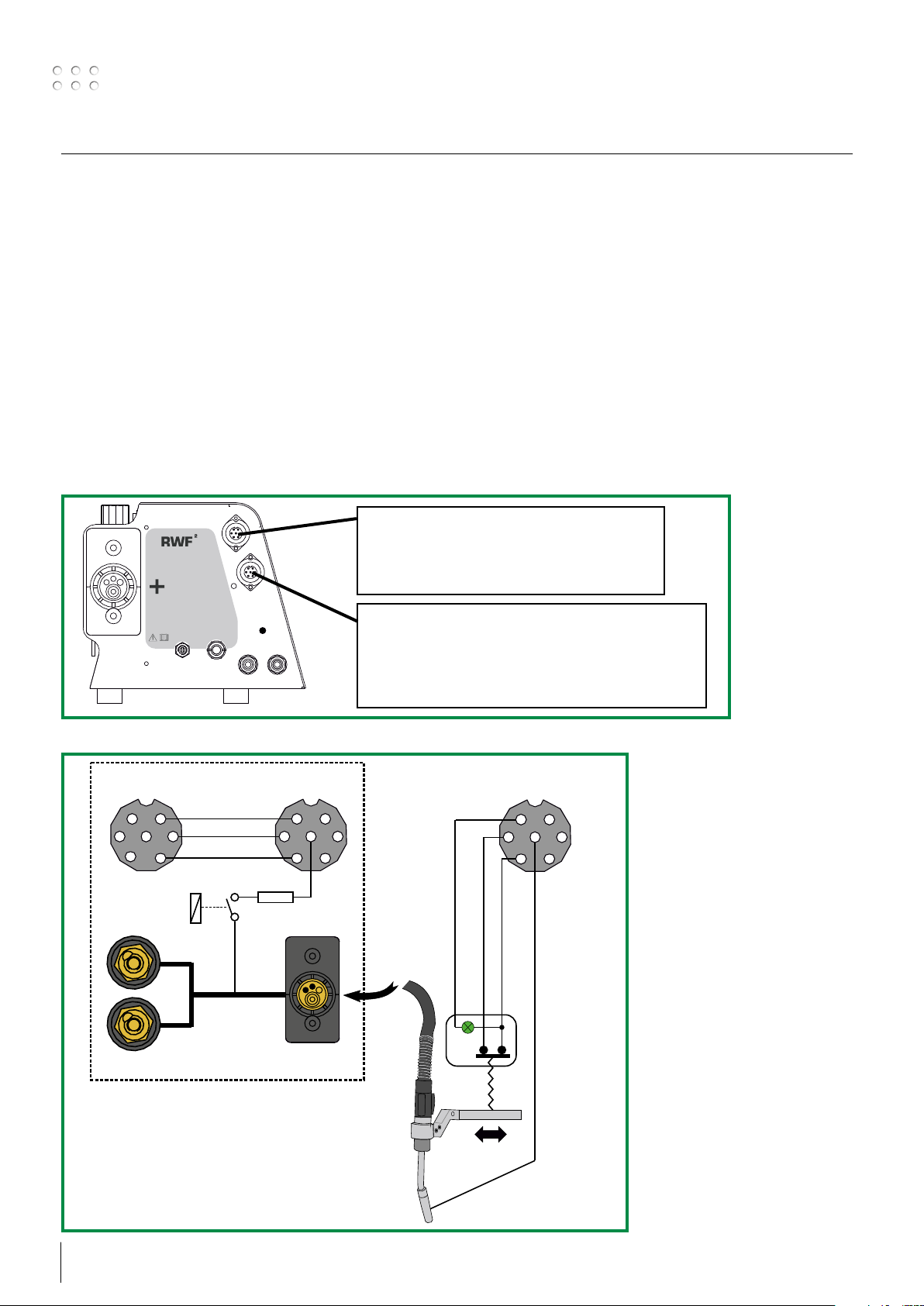
How to connect the installation
Touch sensing
For exact positioning of the welding torch, it is possible to use the Touch Sensing signal.
This option is available when using Fieldbus communication only.
When the welding wire has contact to the work piece, the robot/controller is told so by changing the
status of an output bit. Touch sensing can also be connected to the gas nozzle.
N.B. Gas nozzle sensing is automatically enabled through a relay when activating touch sensing. The relay
will, for safety reasons, disconnect the gas nozzle sense signal during welding.
Activate Touch sensing by enabling the Touch sensing input bit.
E.x. For Sigma Galaxy this is input Bit # 123. See Fieldbus configuration file for more details.
Read the Touch sensing status output bit.
When the welding wire (or optional the gas nozzle) has contact to work piece, while not welding:
E.x. For Sigma Galaxy output Bit # 147 is ON when there is contact, and OFF when no contact.
See Fieldbus configuration file for more details.
Collision protection signal to robot controller
Pin 1: 0V from robot controller
Pin 2: +24V from robot controller
Pin 3: Collision signal to robot controller
RWF
AIR Clean
Max.8 bar
2
To robot controller To collision sensor &
Male
1
3
Torch gas
nozzle sense
relay
Welding +
from power source
2
0V
24V
Collision signal
1K 50WΩ
touch sensor
Female
1
2
7
3
ZA
Collision protection signal and touch sense to torch
Pin 1: 0V to collision sensor
Pin 2: +24V to collision sensor
Pin 3: Collision signal from collision sensor
Pin 7: Touch sense connection to gas nozzle
To RWF² collision
sensor & touch sensor
Male
1
2
7
3
Collision
sensor
Torch gas
nozzle sense
signal
8 9
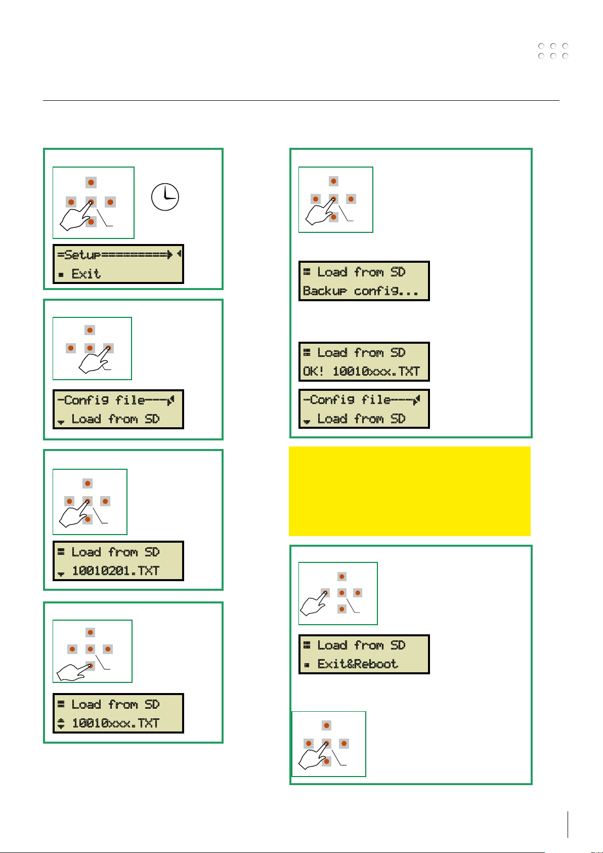
How to do the first configuration and setup
RIGHT
DOWN
ENTER
LEFT
UP
3 SECS
RIGHT
DOWN
ENTER
LEFT
UP
RIGHT
DOWN
ENTER
LEFT
UP
RIGHT
DOWN
ENTER
LEFT
UP
RIGHT
DOWN
ENTER
LEFT
UP
RIGHT
DOWN
ENTER
LEFT
UP
RIGHT
DOWN
ENTER
LEFT
UP
Choose the configuration file suitable for your selection of communication method, from the list on page
33-64. The configuration file is placed on the preinstalled SD card.
Enter Setup menu
1
=Setup=========ÇÄ
Á Exit
Choose Config file setting
2
-Config file---Ã
¾ Load from SD
Select With eNteR
5
During loading process the display will indicate
that a backup file is being saved on the SD card.
Æ Load from SD
Backup config...
Indication of successful loading
Æ Load from SD
OK! 10010xxx.TXT
-Config file---Ã
¾ Load from SD
Enter Load menu
3
Æ Load from SD
¾ 10010201.TXT
Scroll to the desired file
4
Æ Load from SD
¿ 10010xxx.TXT
IMPORTANT
Fieldbus serial communication:
Continue to page 11 without leaving the Setup menu.
Analog communication:
Continue on this and the next page to complete setup.
Leave the Setup menu
6
Æ Load from SD
Á Exit&Reboot
Confirm with ENTER
Setup for Analog communication is finished
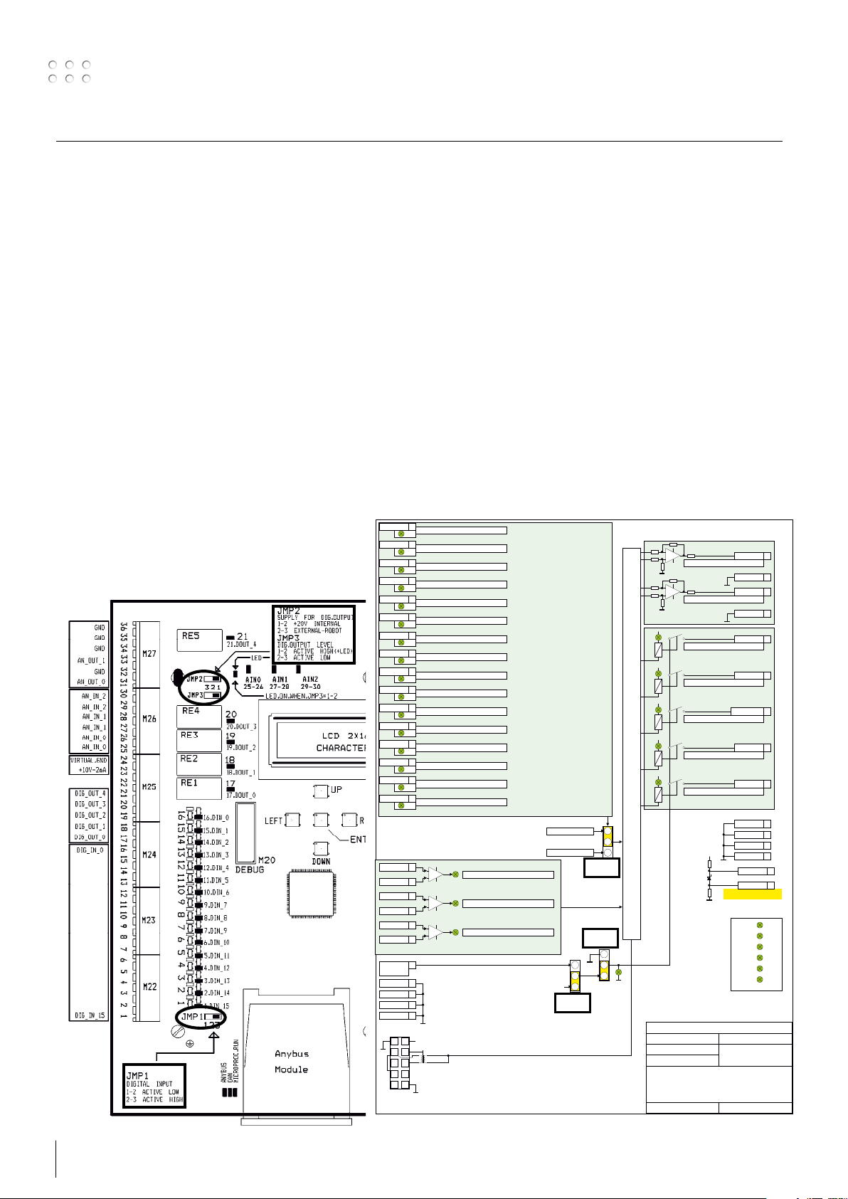
Jumper settings
DiGitAl iNPUtS leVel - JMP1
The active input level for all inputs is determined by positioning of jumper JMP1.
JMP1 position 1-2 = Active LOW
JMP1 position 2-3 = Active HIGH – (default)
DiGitAl OUtPUtS leVel – JMP3
The active output level on all outputs is determined by positioning of jumper JMP3.
JMP3 position 1-2 = Active HIGH – (default)
JMP3 position 2-3 = Active LOW
DiGitAl OUtPUtS VOltAGe SOURce – JMP2
Another jumper (JMP2) is provided to configure the voltage level of all the digital outputs.
JMP2 position 1-2 = +20VDC supplied by RCI – (default)
JMP2 position 2-3 = +24VDC supplied by external power supply from robot or custom hardware
XX function 16
Function defined by the configurations file
D16
XX function 15
Function defined by the configurations file
XX function 14
XX function 13
XX function 12
XX function 11
XX function 10
XX function 09
XX function 08
XX function 07
XX function 06
XX function 05
XX function 04
XX function 03
XX function 02
XX function 01
Digital input
Analog input
Robot supply
+ 24 VDC
GND 32
GND 34
GND 35
GND 36
Connect to
welding machine
6
10
D28
Function defined by the configurations file
D40
Function defined by the configurations file
D52
Function defined by the configurations file
D17
Function defined by the configurations file
D29
Function defined by the configurations file
D41
Function defined by the configurations file
D53
Function defined by the configurations file
D18
Function defined by the configurations file
D30
Function defined by the configurations file
D42
Function defined by the configurations file
D54
Function defined by the configurations file
D19
Function defined by the configurations file
D31
Function defined by the configurations file
D43
Function defined by the configurations file
D55
25XX function +
26XX function -
27XX function +
28XX function -
29XX function +
30XX function -
22
1
+ 55V
+ 11V
Can-bus
5
M18
Function defined by the configurations file
D1
Function defined by the configurations file
D3
Function defined by the configurations file
D2
Digital input: Active High
Digital input: Active Low
Jumper 2
3
2
+ 20 VDC
1
JMP2
Jumper 1
JMP1
JMP3
Jumper 3
3
2
1
Output active
high
Function
Function
Processor
+
D56
RE1
Function
+
D57
RE2
Function
+
D58
RE3
Function
+
D59
RE4
Function
+
D60
RE5
Function
3
Analog
2
Input
1
Digital
Input
Can-Bus
D61
Arthur Nielsen
Robotinterface mk3
Basic setup
Rev: 0 15-01-2014
Function defined by the configurations file
Function defined by the configurations file
Function defined by the configurations file
Function defined by the configurations file
Function defined by the configurations file
Function defined by the configurations file
Function defined by the configurations file
50
50
+ 15
200 200
10VDC
2mA
Potentiometer supply
Migatronic A/S
XX function 31
GND 32
XX function 33
GND 34
Analog output
XX function 17
XX function 18
XX function 19
XX function 20
XX function 21
Digital output
GND 32
GND 34
GND 35
GND 36
10 VDC 23
Virtuel Gnd 24
This is NOT GND!
5V
D74
3.3V
D75
-15V
D67
D66
15V
D65
20V
Powersupply
5V can-bus
D7
10 11
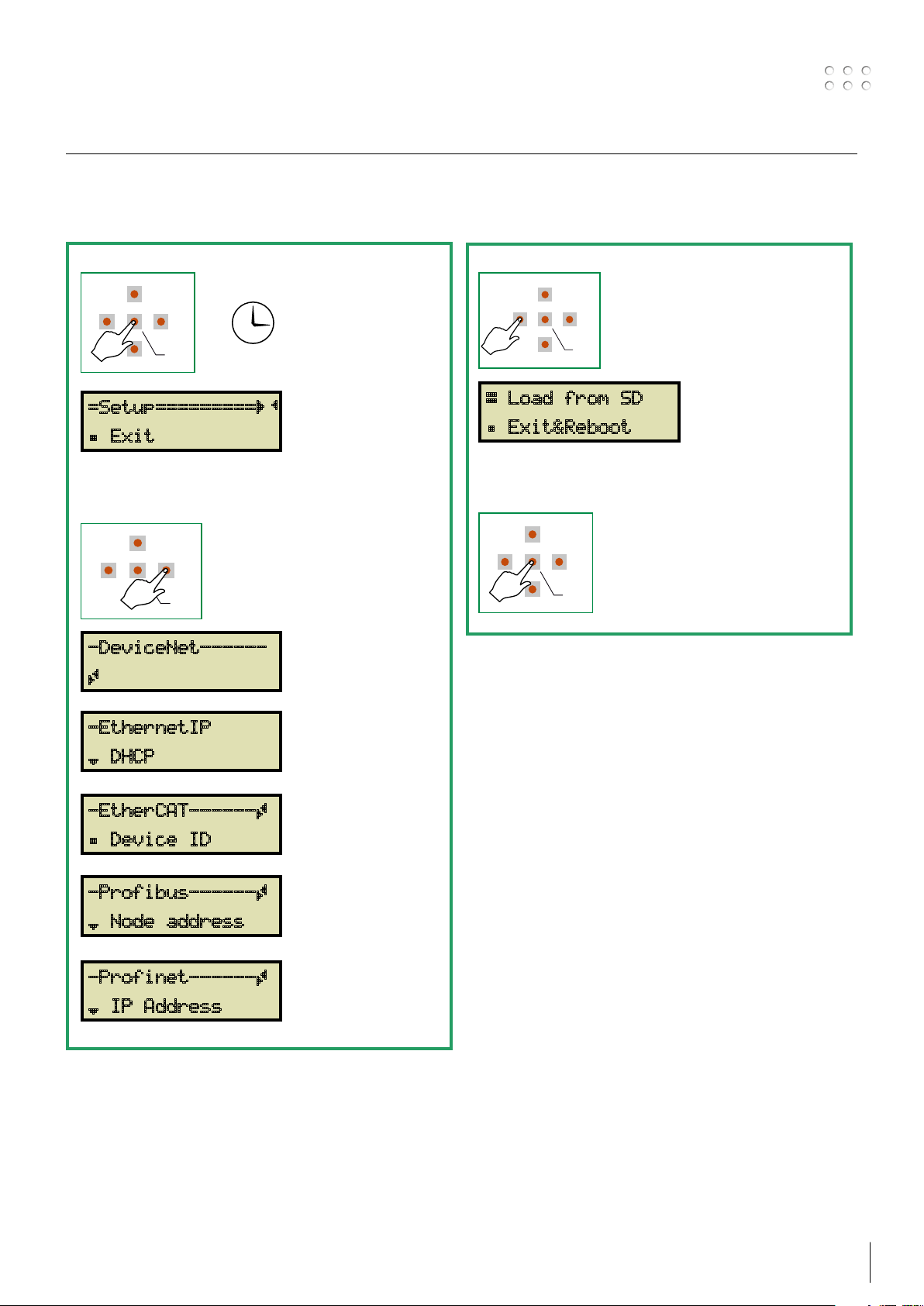
Fieldbus serial communication setup
RIGHT
DOWN
ENTER
LEFT
UP
RIGHT
DOWN
ENTER
LEFT
UP
RIGHT
DOWN
ENTER
LEFT
UP
3 SECS
RIGHT
DOWN
ENTER
LEFT
UP
The communication address information needed by the installed Anybus module depends on the type of
installed Anybus module. See the page corresponding to your network type.
Enter Setup menu
1
=Setup=========ÇÄ
Á Exit
Press RIGHT until the display shows the
name of your Anybus module.
-DeviceNet------
Continue on page 20
Ã
Leave the Setup menu
2
Æ Load from SD
Á Exit&Reboot
Confirm with ENTER
-EthernetIP
Continue on page 21
¾ DHCP
-EtherCAT------Ã
Continue on page 22
Á Device ID
-Profibus------Ã
Continue on page 23
¾ Node address
-Profinet------Ã
Continue on page 24
¾ IP Address

Status menu
The initial menu is showing the status of the interface.
No changes of configurations are possible, from here.
For setup see page 15.
È SETUP MENU is LOCKED – NEED PASSWORD
Status: É
1
----->
2
Software ver.:
NOT CONFIGURED
INITIALIZATION
ERROR
RUNNING
DEVICE ERROR
The version code of the installed software is shown
RCI2 1.00
3
Config.name:
12345678.TXT
The file name of the installed configuration file is shown.
The configuration file holds all information needed for correct communication between
robot and welding machine.
UP
LEFT
DOWN
Interface is not configured. Please load a configuration file.
At turn-ON of interface.
An error is present. Check the error log and the error list on page
68-70
The interface is working properly without problems.
An error is present on one of the connected devices, welding
machine or RWF
68-70
2
. Check the error log and the error list on page
RIGHT
ENTER
4
Config.descr:
STANDARD CONFIG#1
5
Anybus Status:
(Not Present)
A text description of the installed configuration file is shown.
The configuration file holds all information needed for correct communication between
robot and welding machine.
When an Anybus module is installed and the correct configuration file is loaded, this menu
is indicating the status of the serial communication and Anybus module status.
Anybus Status: Description
Setup
Network init
Wait process
Idle
Process active
Error
Exception
(not present)
Anybus Setup in progress.
The Anybus module is currently performing network-related
initialization tasks.
Telegrams now contains Process Data (if such data is mapped),
however the network Process Data channel is not yet active.
Communication between robot and Anybus module is missing.
Check cable between robot and RCI
Check network setup.
The network interface is idle. The exact interpretation of this
state is network specific.
Depending on the network type, the Read Process Data may be
either updated or static (unchanged).
The network Process Data channel is active and error free
There is at least one serious network error.
Enter setup menu – Diagnostic, and readout the error code.
The module has ceased all network participation due to a host
application-related error.
This state is unrecoverable, i.e. the module must be restarted
in order to be able to exchange network data. Exchange the
Anybus module if a restart does not solve the problem.
2
RCI
is not configured for use of Anybus module
2
interface.
12 13

Status menu
16 15
141312 11
10 9 8
7 6
5
4
3
2 1
16 15 14 13 12 11 10 9 8 7 6 5 4 3 2 1
D
I
G
_
I
N
_
1
5
D
I
G
_
I
N
_
0
1
0
.
D
I
N
_
6
6
.
D
I
N
_
1
0
5
.
D
I
N
_
1
1
8
.
D
I
N
_
8
4
.
D
I
N
_
1
2
7
.
D
I
N
_
9
1
.
D
I
N
_
1
5
3
.
D
I
N
_
1
3
1
4
.
D
I
N
_
2
1
5
.
D
I
N
_
1
1
3
.
D
I
N
_
3
1
1
.
D
I
N
_
5
1
2
.
D
I
N
_
4
9
.
D
I
N
_
7
2
.
D
I
N
_
1
4
1
6
.
D
I
N
_
0
0 1 2 3 4 5 6 7 8 9 A B C D E F
21 20 19 18 17
D
I
G
_
O
U
T
_
0
1
9
.
D
O
U
T
_
2
2
0
.
D
O
U
T
_
3
1
8
.
D
O
U
T
_
1
2
1
.
D
O
U
T
_
4
01234
D
I
G
_
O
U
T
_
1
D
I
G
_
O
U
T
_
2
D
I
G
_
O
U
T
_
4
D
I
G
_
O
U
T
_
3
R
E
1
R
E
2
R
E
3
R
E
4
R
E
5
2
0
1
9
1
8
1
7
2
1
1
7
.
D
O
U
T
_
0
Digital Inputs:
6
__2___67_9AB___F
Indication of activity on the digital inputs when RCI2 is setup for “analog”
use. The displayed number is referring to the digital input number.
See example below.
Displayed numbers
Connector numbers
Digital input numbers
Digital Outputs:
7
0__3_
Indication of activity on the digital output
when RCI2 is setup for “analog” use
The displayed number is referring to the digital output number.
See example below
Displayed numbers
Connector numbers
Digital output numbers

Status menu
29 28 27 26 25
AIN0
25-26
RE2
RE3
RE4
RE5
30
AN_ IN_ 2
AN_ IN_ 2
AN_ IN_ 1
AN_ IN_ 1
AN_ IN_ 0
AN_ IN_ 0
LCD
CHARA
AIN1
27-28
AIN2
29-30
DOWN
Analog Inputs:
8
0=7.53V 1=10.00V
Analog Outputs:
9
0=00.00V 1=7.89V
The 3 analog inputs can be monitored in this menu.
The LED brightness will vary according to the analog voltage
LEFT
Analog Inputs:
2=0.00V
The 2 analog outputs, AN_OUT_1 and AN_OUT_0
can be monitored in this menu.
UP
RIGHT
ENTER
Clock: 09:35:47
10
FRI 2013-11-08
36 35 34 33 32
GND
GND
GND
AN_OUT_1
GND
AN_OUT_0
M27
31
Local time and date, used in ERROR LOG reports,
and indication of when BACKUP files were stored.
14 15
Setup menu
RIGHT
DOWN
ENTER
LEFT
UP
3 SECS
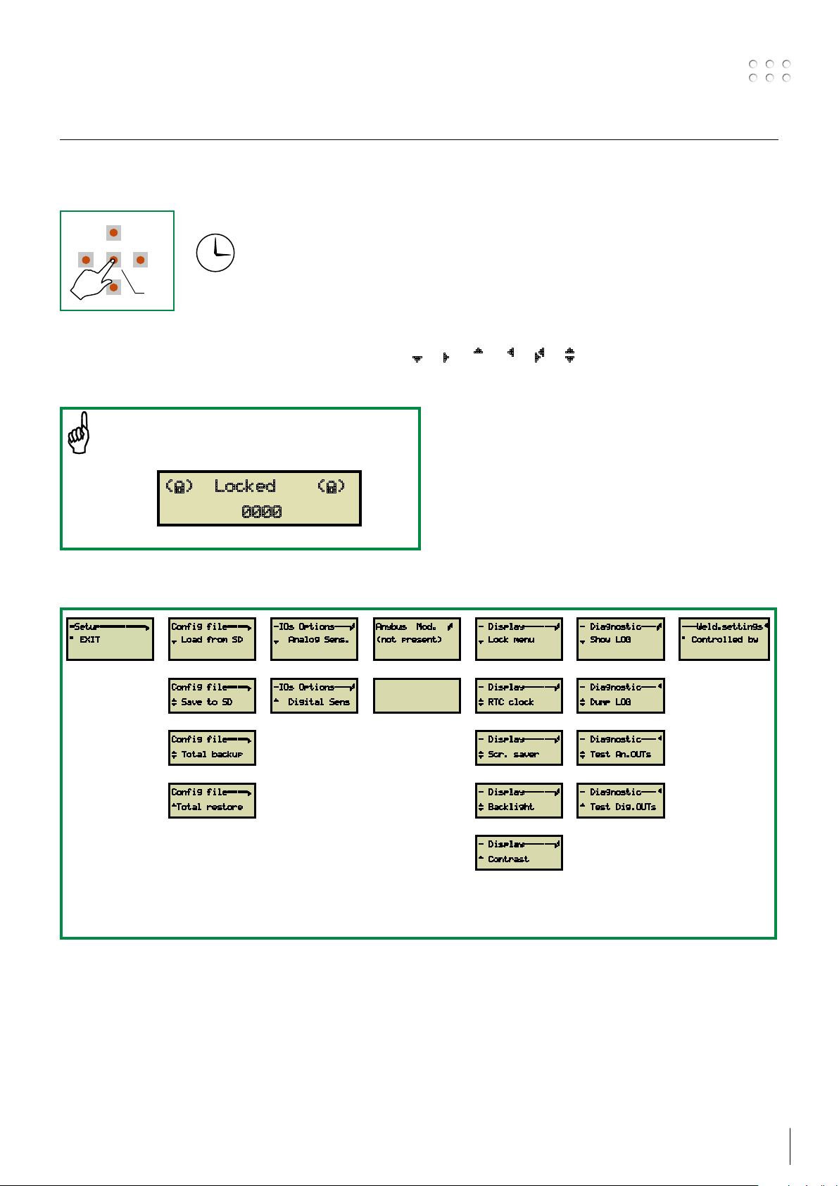
This page is showing the structure of SETUP MENU for the interface.
In this area it is possible to CONFIGURE different parameters of the interface
Follow the navigation arrows as shown in the display ¾ Â À Ä Ã ¿
Enter the unlock code and press ENTER
if this information is shown
(È) Locked (È)
0000
Menu structure
=Setup=========Â
° EXIT
(1)
Config file====Â
¾ Load from SD
(2)
Config file====Â
¿ Save to SD
-IOs Options---Ã
¾ Analog Sens.
(3)
-IOs Options---Ã
À Digital Sens
Config file====Â
¿ Total backup
Config file====Â
ÀTotal restore
See the following pages for menu description
Anybus Mod. Ã
(not present)
(4)
Depending on
installed module.
See description
- Display------Ã
¾ Lock menu
(5)
- Display------Ã
¿ RTC clock
- Display------Ã
¿ Scr. saver
- Display------Ã
¿ Backlight
- Display------Ã
À Contrast
- Diagnostic---Ã
¾ Show LOG
(6)
- Diagnostic---Ä
¿ Dump LOG
- Diagnostic---Ä
¿ Test An.OUTs
- Diagnostic---Ä
À Test Dig.OUTs
---Weld.settingsÄ
° Controlled by
(7)
Setup menu
MIGA_CFG
ROBOT
1000xxxx.txt
1000xxxx.PDF
(configuration file description)
(configuration file)
RIGHT
DOWN
ENTER
LEFT
UP
RIGHT
DOWN
ENTER
LEFT
UP
RIGHT
DOWN
ENTER
LEFT
UP
RIGHT
DOWN
ENTER
LEFT
UP
UP
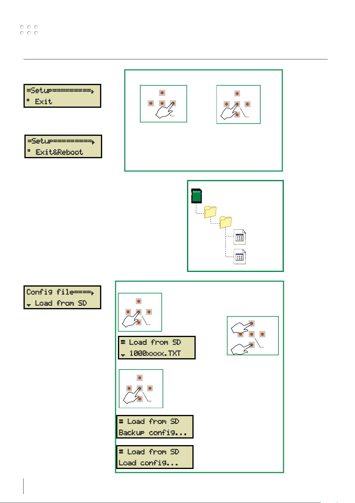
(1) – Setup Exit
Next menu Leave the menu with ENTER
=Setup=========Â
° Exit
Exit&Reboot is shown when changes have been made
=Setup=========Â
° Exit&Reboot
to settings in other menus, and the interface needs
to reboot to become active again. Not all changes to
parameters will force the REBOOT
(2) – Config file
A configuration file, holding information on input and
output setting, must be loaded into RCI2. Take care that
the inserted SD card holds the configuration files in a file
structure as shown to the right.
List of available configuration files see page 33-64.
Customized configuration files can be produced on
request.
Config file====Â
Enter Load menu
¾ Load from SD
Press ENTER Select file
RIGHT
ENTER
Æ Load from SD
¾ 1000xxxx.TXT
LEFT
DOWN
Confirm with ENTER
A backup file is saved
automatically on the SD
card, every time a new file is
Backup file name is
Æ Load from SD
BACK00.TXT
BACK01.TXT etc etc.
Backup config...
loaded.
Latest backup file has the
highest number
16 17
Æ Load from SD
Load config...
Setup menu
RIGHT
DOWN
ENTER
LEFT
UP
RIGHT
DOWN
ENTER
LEFT
UP
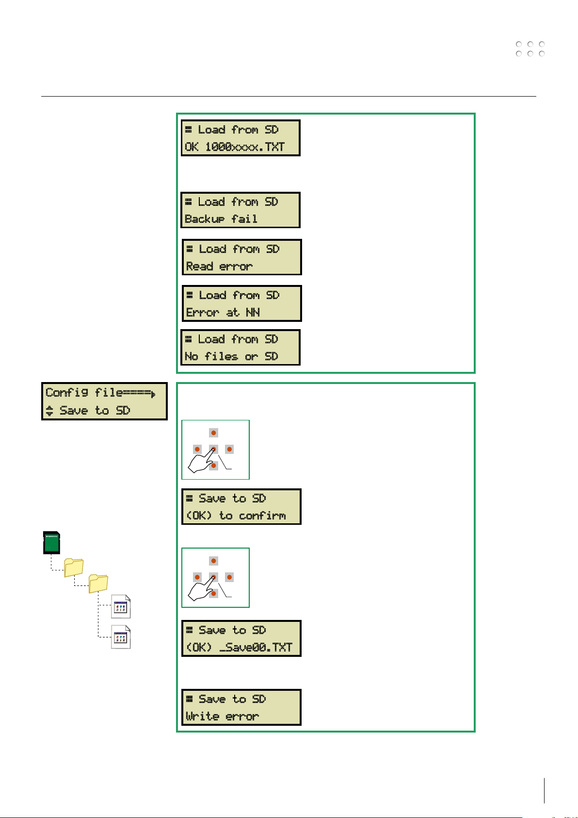
Configuration file is saved
successfully.
Æ Load from SD
OK 1000xxxx.TXT
Possible errors during reading and saving to SD card
Config file====Â
¿ Save to SD
This function is used when
you want to copy the
installed configuration
file to another SD card.
Configuration file only is
copied.
Æ Load from SD
Backup fail
Æ Load from SD
Check if there is enough space on the
SD card, SD write protected OFF or
SD card is defective.
Impossible to read the selected file or
problems on SD card.
Read error
Æ Load from SD
Syntax error at line NN.
Error at NN
Æ Load from SD
SD card folder or files are missing.
No files or SD
Save a copy of the configuration file to a SD card.
Press Enter
Æ Save to SD
(OK) to confirm
Press Enter
MIGA_CFG
ROBOT
_SAVE00.TXT
Saved file name is
SAVE00.TXT
SAVE01.TXT etc etc.
_SAVE01.TXT
Æ Save to SD
(OK) _Save00.TXT
Possible errors during reading and saving to SD card
Æ Save to SD
SD card or folders are missing or
problems on the SD card
Write error
Setup menu
RIGHT
DOWN
ENTER
LEFT
UP
RIGHT
DOWN
ENTER
LEFT
UP
RIGHT
DOWN
ENTER
LEFT
UP
RIGHT
DOWN
ENTER
LEFT
UP
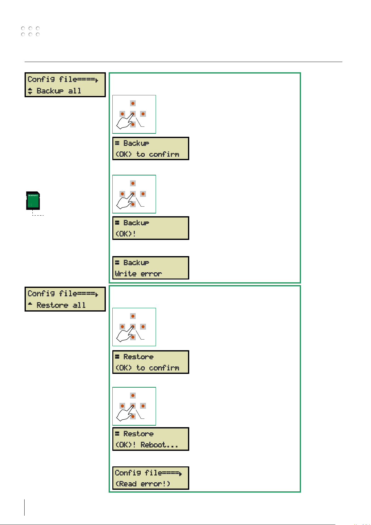
RCI2.BCK
Config file====Â
¿ Backup all
A backup of all
configurations settings and
Anybus network setups are
stored on the SD card.
This function is useful
when replacing the RCI2
after a breakdown, or
when cloning of RCI2 is
needed.
Previous backup file will be
overwritten.
A Total backup of all settings to the SD card.
Press Enter
Æ Backup
(OK) to confirm
Press Enter
Æ Backup
Saved file name is RCI2.BCK
saved at the root of SD card.
(OK)!
Possible errors during backup to SD card
Config file====Â
À Restore all
Upload of backup file
with all configuration
setups and Anybus
network setups stored on
the SD card.
This function is useful
when replacing the RCI2
after a breakdown, or
when cloning the RCI2 is
needed.
Æ Backup
SD card or folders are missing or
problems on the SD card
Write error
Restore settings from backup of all settings to the SD card.
Press Enter
Æ Restore
(OK) to confirm
Press Enter
Æ Restore
(OK)! Reboot...
Read file name
URI_BCK.BIN
from the root of SD card.
Possible errors during restore from SD card
Config file====Â
SD card or folders are missing or
problems on the SD card.
(Read error!)
18 19
Setup menu
RIGHT
DOWN
ENTER
LEFT
UP
RIGHT
DOWN
ENTER
LEFT
UP
RIGHT
DOWN
ENTER
LEFT
UP
RIGHT
DOWN
ENTER
LEFT
UP
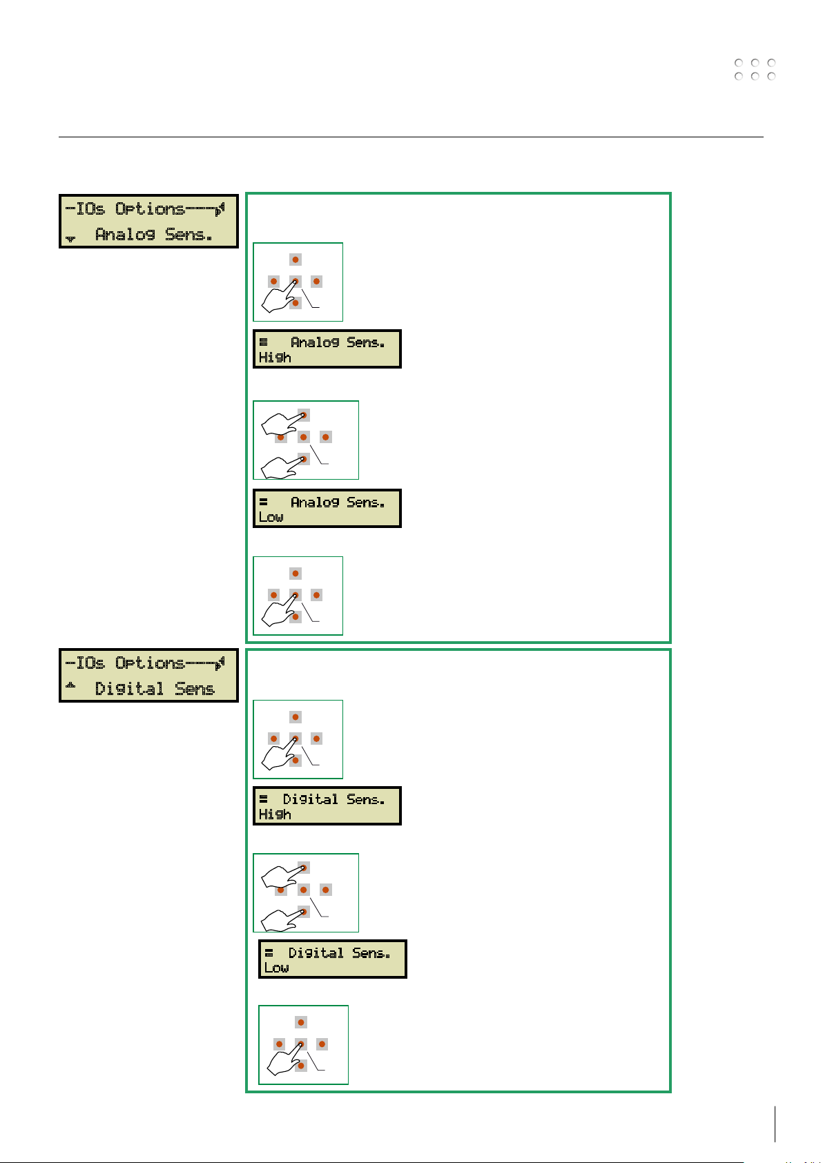
(3) – IOs options
-IOs Options---Ã
¾ Analog Sens.
This filter allows change of
sensitivity to background
noise on all inputs. LOW is
default.
Change the sensitivity for analog inputs
Press Enter
Æ Analog Sens.
High
High sensitivity = no filter
Press Down or Up
UP
DOWN
RIGHT
ENTER
Low sensitivity = active filter
LEFT
Æ Analog Sens.
Low
Press Enter
-IOs Options---Ã
À Digital Sens
This filter allows change of
sensitivity to background
noise on all inputs. LOW is
default.
Change the sensitivity for digital inputs
Press Enter
Æ Digital Sens.
High
High sensitivity = no filter
Press Down or Up
UP
DOWN
RIGHT
ENTER
Low sensitivity = active filter
LEFT
Æ Digital Sens.
Low
Press Enter
Setup menu
RIGHT
DOWN
ENTER
LEFT
UP
RIGHT
DOWN
ENTER
LEFT
UP
RIGHT
DOWN
ENTER
LEFT
UP
UP
RIGHT
DOWN
ENTER
LEFT
UP
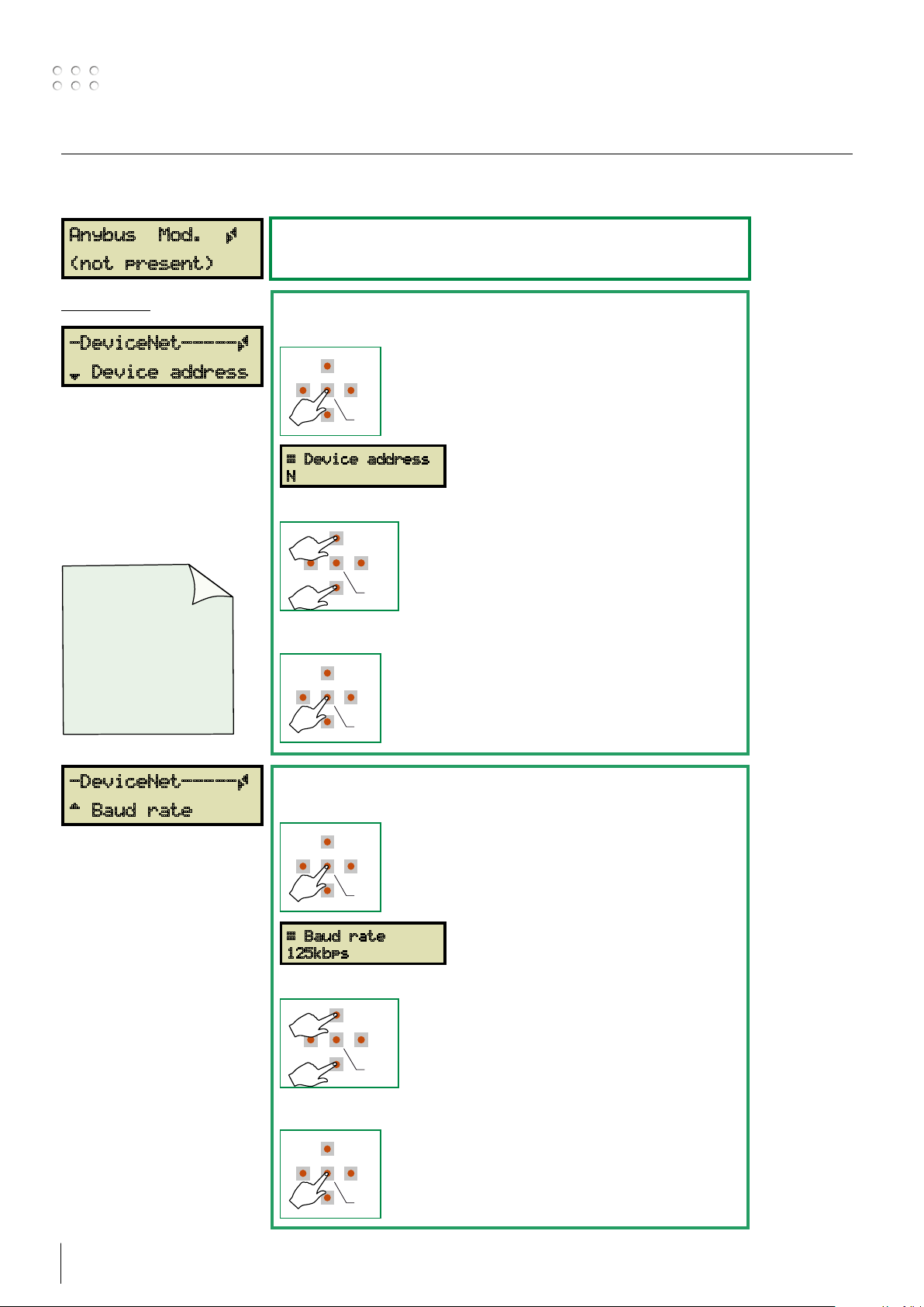
(4) – Anybus module
Anybus Mod. Ã
(not present)
DeviceNet
-DeviceNet-----Ã
¾ Device address
The interface automatically
detects and identifies the
installed Anybus module
and consequently displays
different scenarios,
depending on the
information needed by the
Anybus module.
The EDS file
needed by the
robot controller/PLC
can be found on the
SD card, or
downloaded from
www.migatronic.com
MY MIGATRONIC
No Anybus module is installed or detected.
DeviceNet address setup
Press Enter
Æ Device address
N
Press Down or Up
Press Enter to leave Device address
LEFT
DOWN
UP
Set the network device address.
N is in the range 0 to 255.
RIGHT
ENTER
-DeviceNet-----Ã
À Baud rate
DeviceNet baud rate setup
Press Enter
Æ Baud rate
125kbps
Press Down or Up
Set the network baud rate.
Possible settings.
LEFT
DOWN
RIGHT
ENTER
125 - 250 - 500kbps and Autobaud
Press Enter to leave
20 21
RIGHT
DOWN
ENTER
LEFT
UP
UP
RIGHT
DOWN
ENTER
LEFT
UP
Setup menu
RIGHT
DOWN
ENTER
LEFT
UP
RIGHT
DOWN
ENTER
LEFT
UP
RIGHT
DOWN
ENTER
LEFT
UP
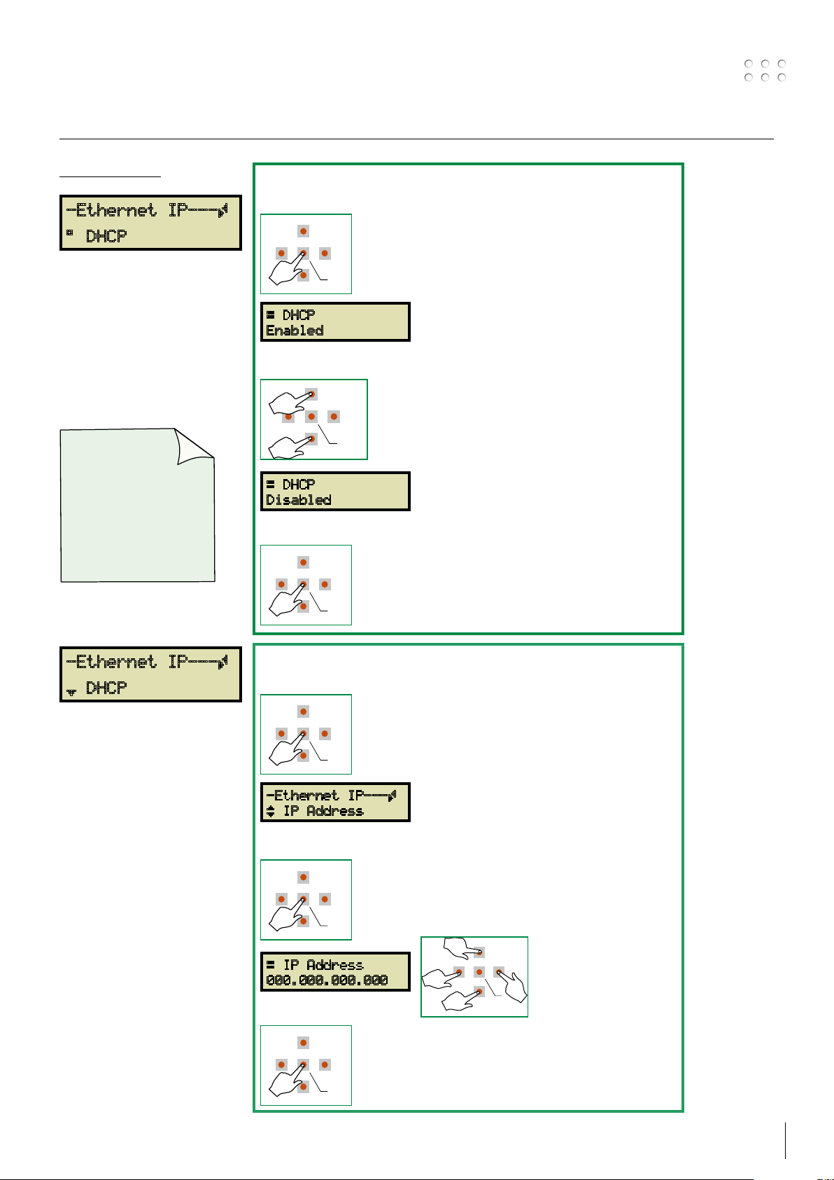
ETHERNET/IP
-Ethernet IP---Ã
° DHCP
The interface automatically
detects and identifies the
installed Anybus module
and consequently displays
different scenarios,
depending on the
information needed by the
Anybus module.
The EDS file
needed by the
robot controller/PLC
can be found on the
SD card, or
downloaded from
www.migatronic.com
MY MIGATRONIC
DHCP setting
Press Enter
Æ DHCP
Enabled
Press Down or Up
DOWN
RIGHT
ENTER
LEFT
Æ DHCP
Disabled
Press Enter to leave
DHCP = Enabled
IP address is issued by the DHCP network
server
DHCP = Disabled
IP address must be configured manually
-Ethernet IP---Ã
¾ DHCP
IP address manual setup
Press Enter
-Ethernet IP---Ã
¿ IP Address
Press Enter
Æ IP Address
000.000.000.000
Press Enter to leave
UP
LEFT
DOWN
Set the IP address as
specified by the robot
RIGHT
or network controller.
E.x. 192.168.000.010
ENTER
Setup menu
RIGHT
DOWN
ENTER
LEFT
UP
UP
RIGHT
DOWN
ENTER
LEFT
UP
RIGHT
DOWN
ENTER
LEFT
UP
RIGHT
DOWN
ENTER
LEFT
UP
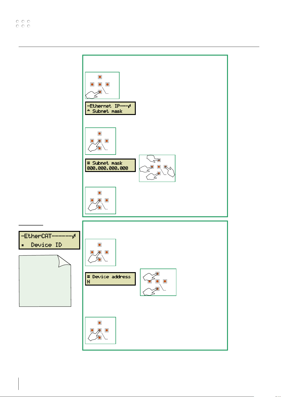
IP address manual setup SUBNET MASK
Press Down
DOWN
RIGHT
ENTER
LEFT
-Ethernet IP---Ã
À Subnet mask
Press Enter
Æ Subnet mask
000.000.000.000
Press Enter to leave
UP
LEFT
DOWN
Set the IP subnet mask
address as specified by
RIGHT
the robot or network
controller.
ENTER
E.x. 255.255.255.000
EtherCAT
-EtherCAT------Ã
Á Device ID
The ESI file
needed by the
robot controller/PLC
can be found on the
SD card, or
downloaded from
www.migatronic.com
MY MIGATRONIC
Device ID setup
Press Enter
Æ Device address
N
Press Enter
LEFT
DOWN
UP
Set the Device ID as
specified by the robot
or network controller.
RIGHT
N is in the range 0 to
ENTER
65535.
22 23
Setup menu
RIGHT
DOWN
ENTER
LEFT
UP
RIGHT
DOWN
ENTER
LEFT
UP
UP
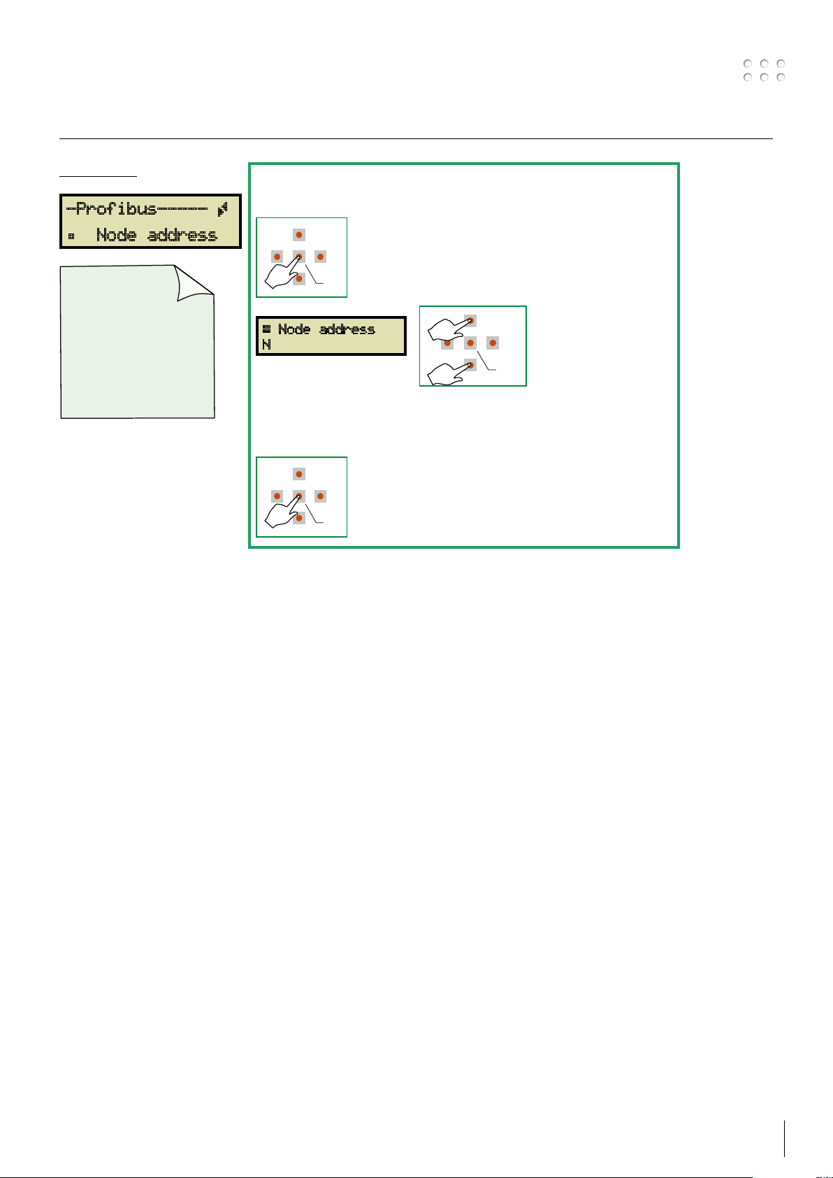
PROFIBUS
-Profibus----- Ã
Á Node address
The GSD/GSE file
needed by the
robot controller/PLC
can be found on the
SD card, or
downloaded from
www.migatronic.com
MY MIGATRONIC
Node address setup
Press Enter
Æ Node address
N
Press Enter
LEFT
DOWN
Set the node address
as specified by the
robot or network
RIGHT
controller.
ENTER
N is in the range 0 to
125 and SSA
(Set Slave Address =
Master is setting the
address)
Setup menu
RIGHT
DOWN
ENTER
LEFT
UP
RIGHT
DOWN
ENTER
LEFT
UP
RIGHT
DOWN
ENTER
LEFT
UP
RIGHT
DOWN
ENTER
LEFT
UP
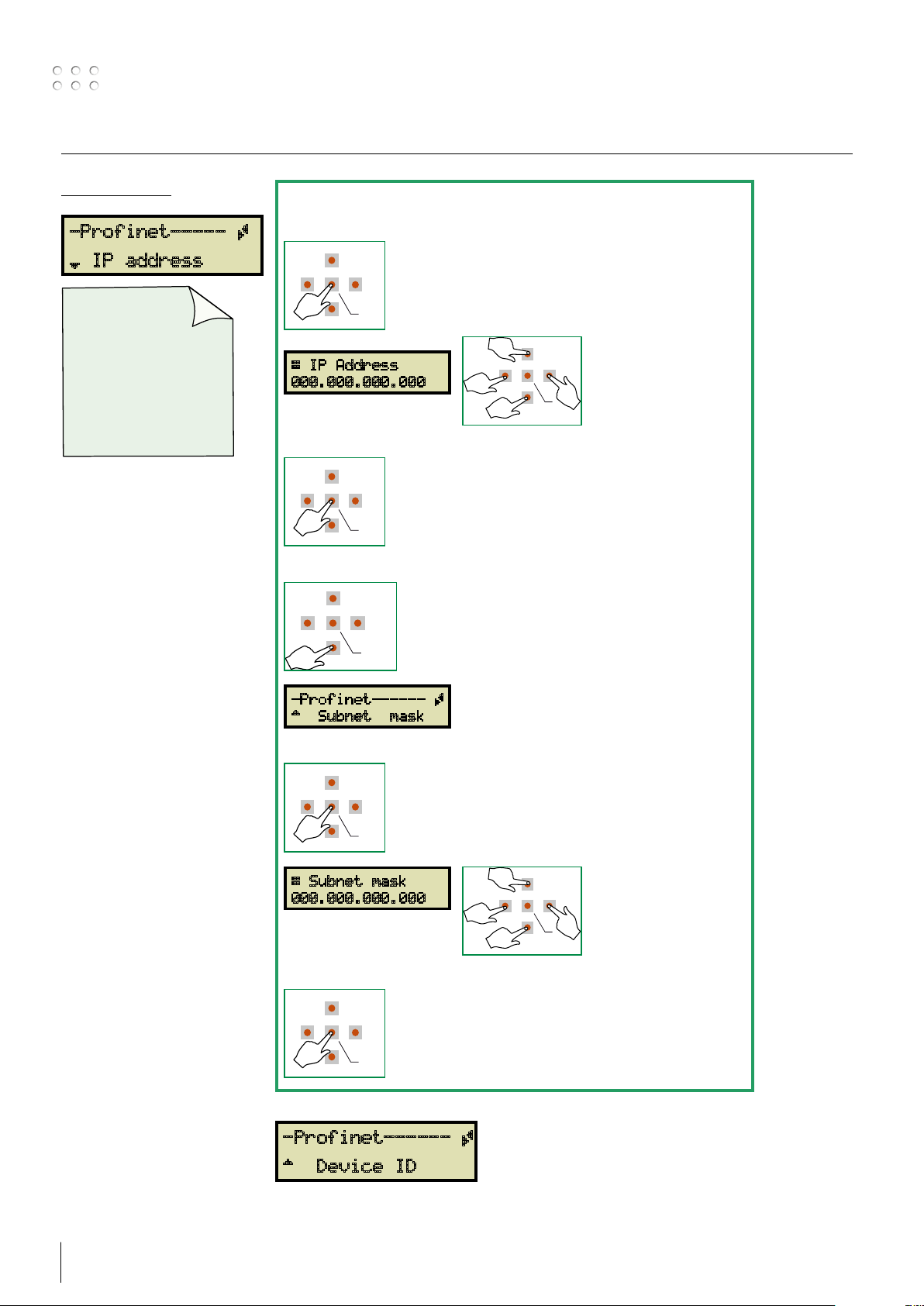
PROFINET IO
-Profinet----- Ã
¾ IP address
The GSDML file
needed by the
robot controller/PLC
can be found on the
SD card, or
downloaded from
www.migatronic.com
MY MIGATRONIC
IP address setup
Press Enter
Æ IP Address
000.000.000.000
Press Enter
Press Down
UP
LEFT
RIGHT
UP
Set the IP address as
specified by the robot
DOWN
RIGHT
or network controller.
E.x. 192.168.000.010
ENTER
LEFT
ENTER
DOWN
-Profinet------ Ã
À Subnet mask
Press Enter
Æ Subnet mask
000.000.000.000
Press Enter to leave
UP
Set the IP subnet mask
address as specified by
DOWN
RIGHT
the robot or network
controller.
ENTER
E.x. 255.255.255.000
LEFT
-Profinet------ Ã
À Device ID
24 25
 Loading...