

Migatronic RALLY MIG 161i User Manual

RALLY MIG 161i
BRUGSVEJLEDNING
USER GUIDE
BETRIEBSANLEITUNG
GUIDE DE L’UTILISATEUR
BRUKSANVISNING
GUIDA PER L’UTILIZZATORE
GEBRUIKERSHANDLEIDING
KÄYTTÖOHJE
GUÍA DE USUARIO
KEZELÉSI ÚTMUTATÓ
PODRĘCZNIK UŻYTKOWNIKA
NÁVOD K OBSLUZE
РУКОВОДСТВО ПОЛЬЗОВАТЕЛЯ
50115018 B2 Valid from 2018 week 21

Dansk ..................................................................3
English ................................................................9
Deutsch .............................................................15
Français .............................................................21
Svenska .............................................................27
Italiano .............................................................33
Nederlands .......................................................39
Suomi ................................................................45
Español .............................................................51
Magyar ..............................................................57
Polski .................................................................63
Česky .................................................................69
Русский ...........................................................75
2
Connection and operation
Warning
Read warning notice and
instruction manual carefully
prior to initial operation and
save the information for later
use.
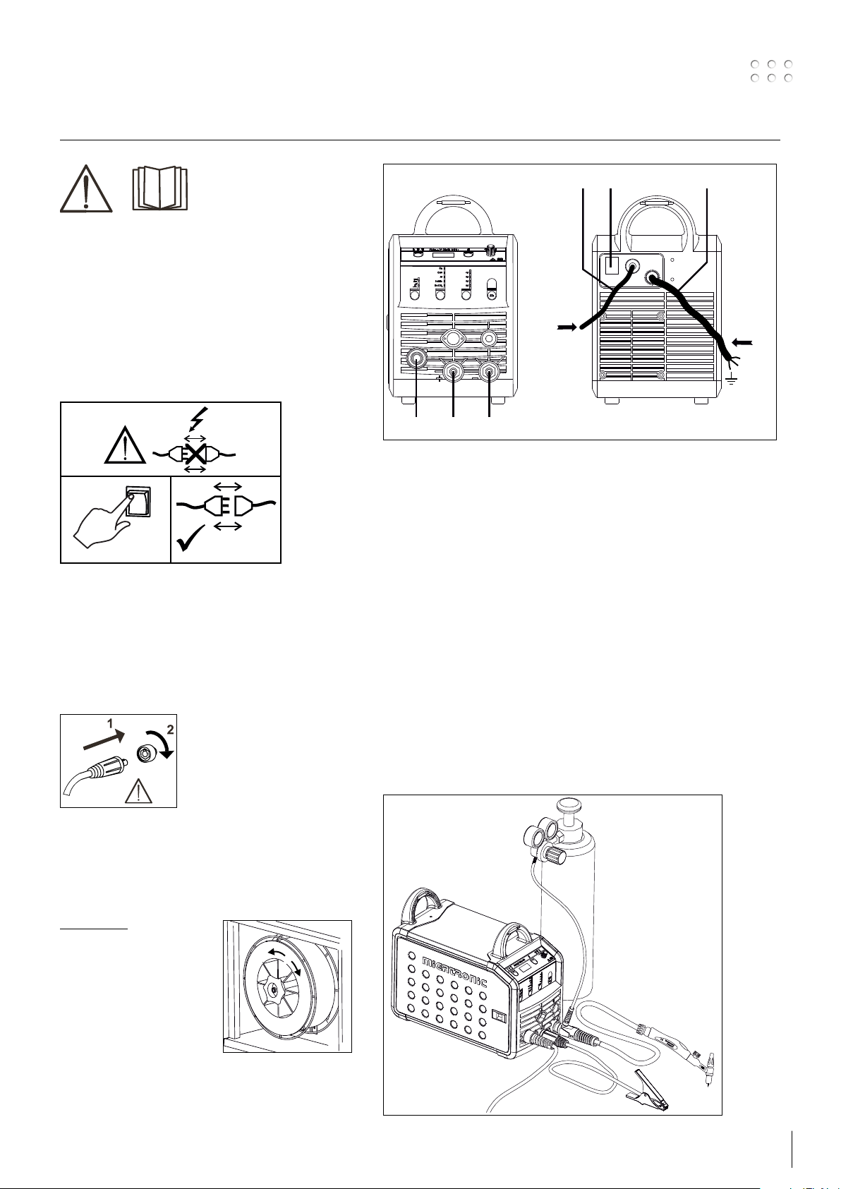
Permissible installation
Mains connection
Connect the machine to the correct mains supply. Please
read the type plate (U1) on the rear side of the machine.
0
l
1
2
3
GAS
max. 8 Bar
4
65
1. Mains connection
2. Power switch
3. Connection of shielding gas
4. Connection of earth clamp or
electrode holder/TIG torch
5. Connection of welding hose
6. Connection of earth clamp or electrode holder
12
Power
N
F
Connection of shielding gas
Connect the gas hose, which branches off from the
back panel of the welding machine (3), to a gas supply
with pressure regulator (0-8 bar). (Note: Some types of
pressure regulators require an output pressure of more
than 2 bar to function optimally).
Important!
In order to avoid destruction
of plugs and cables, good
electric contact is required when
connecting earth cables and
welding hoses to the machine.
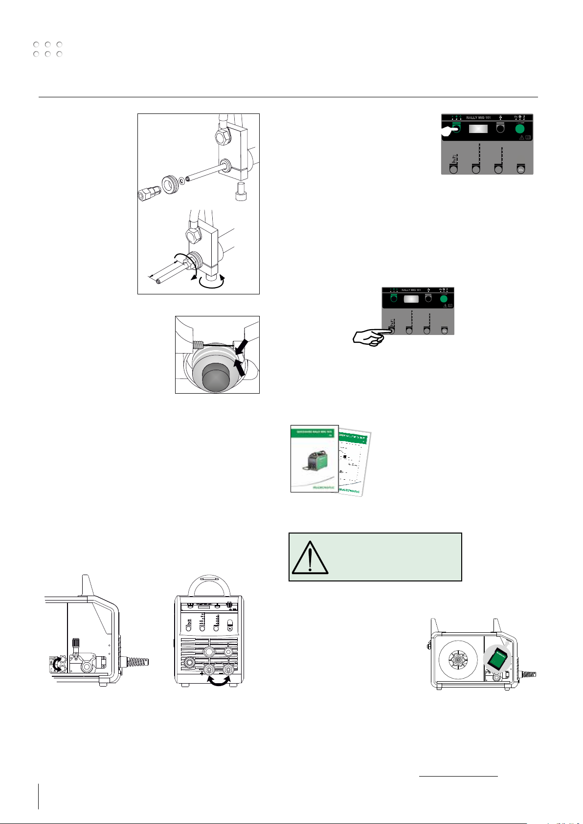
Adjustment of wire drive rolls
The wire brake must ensure that the wire reel brakes
sufficiently before the welding wire runs over the edge
of the reel. The brake force is dependent on the weight
of the wire reel and wire feed speed.
Adjustment:
• Adjust the wire brake by
fastening or loosening
the self-locking nut on
the axle of the wire hub.
Torch adjustment (Dialog torch)
The current size can be adjusted both from the machine
and the welding torch if a welding hose with Dialog
torch is in use. The torch adjustment is passive without
Dialog torch.
Connection of electrode holder for MMA
The electrode holder and earth cable are connected to
plus connection (6) and minus connection (4). Observe
the instructions from the electrode supplier when
selecting polarity.
Installing the TIG torch
9
Connection and operation
Change of wire liner
Welding in aluminium
and MIG brazing requires
a special teflon liner.
Use article no. 81100137
to order kit for
aluminium and MIG
brazing in 1.0 mm wire
with wire liner and inlet
guide.
43
Wire drive rolls
The welding machine is supplied
with turnable wire drive rolls with
V-groove.
For aluminium welding and MIG
brazing, we recommend U-groove/
article no. 82046232.
Selecting welding polarity
Polarity reversal is recommended for certain types of
welding wire, in particular Innershield welding wire. For
recommended polarity, please refer to the welding wire
packaging.
Change of polarity:
1. Disconnect the machine from the mains supply.
2. Dismount the milled nuts at the poles (fig. 1).
3. Reverse the cables (fig. 1).
4. Mount the milled nuts (fig. 1).
5. Exchange earth cable from minus to plus (fig. 2).
6. Connect the machine to the mains supply.
1
2
Inching
The function is used for wire inching
e.g. after change of wire. Wire inching
starts by pressing the green key pad and
simultaneously triggering the torch trigger.
CrNi
Fe
Mix
Fe CO
Wire inching continues even though the
green key pad has been released. It does
not stop until the torch trigger has been released again.
Switch on, press, weld
Welding program setting
• Switch on the welding machine on the main switch (2)
• Select process
• Select type of material and wire diameter
• Set one of the following parameters:
welding current, wire feed speed or thickness of material
• Trim the arc length, if required
• Adjust secondary parameters.
Please read your quickguide
• The machine is now ready to weld
WARNING
Voltage is present on the welding
wire when pressing the welding
hose trigger.
i
Cu
CrNi
1.0
Al
0.9
Fe
Mix
0.8
Fe CO
0.6
2
i
Cu
1.0
Al
0.9
0.8
0.6
2
Change of polarity
10
Software reading
• Insert the SD-card (<2 GB) in
the slide in the right side of the
machine.
• Turn on the machine.
• The display flashes shortly with three
lines.
• Wait until the set current is
displayed.
• Turn off the machine and remove the SD card.
• The machine is now ready for use.
It is necessary to read software inside the new control unit by means of
a SD card, if the control unit has been exchanged.
The software can be downloaded from www.migatronic.com
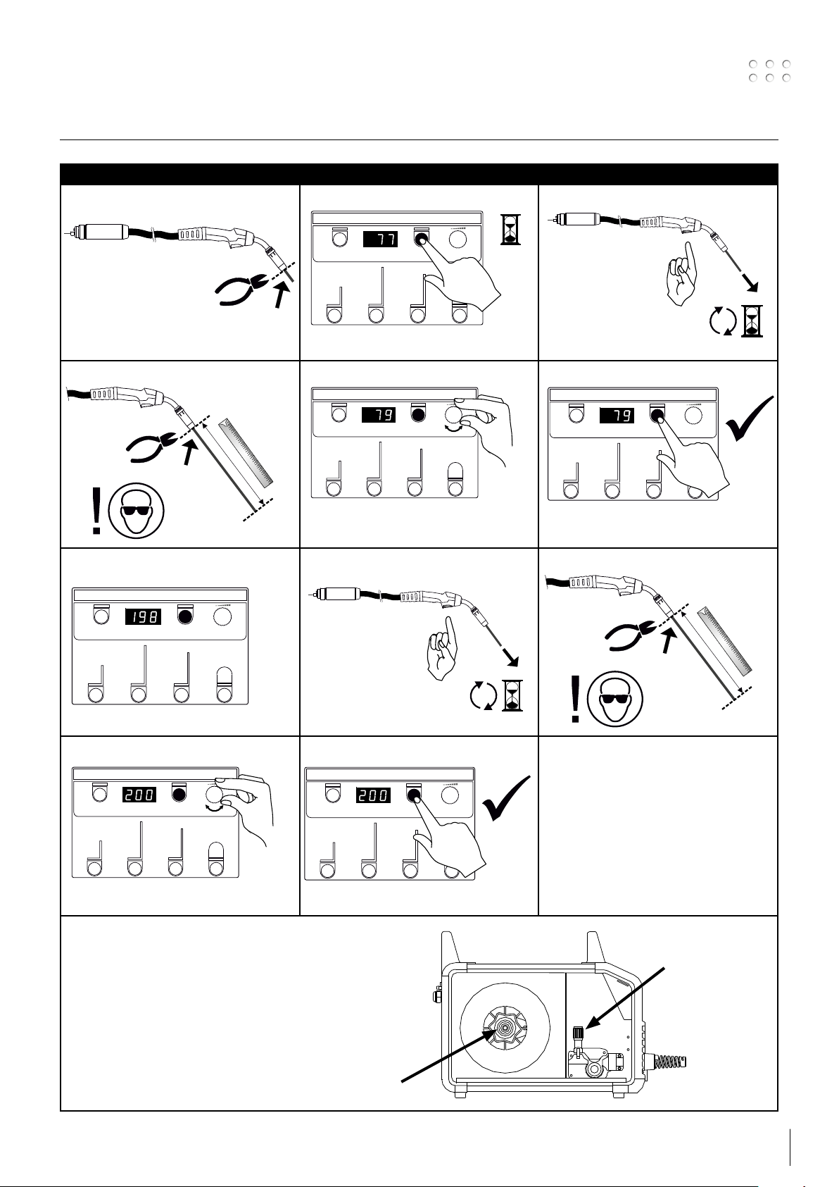
Special functions
10 secs
Calibration of wire feed speed
I II III
IV V VI
e.g. 79 cm
VII VIII IX
X XI
Note:
Adjustment of the pressure on the wire drive rolls and/or
adjustment of the wire brake may influence the wire feed speed
and make it necessary to carry out calibration
e.g. 200 cm
Tightening device for
wire drive rolls
Wire brake
11
 Loading...