

Migatronic OMEGA2, OMEGA2 BOOST, OMEGA2 S User Manual
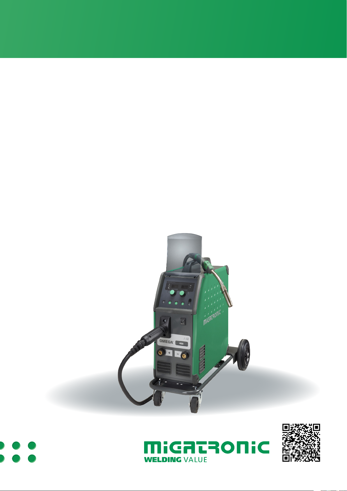
OMEGA2, OMEGA2 BOOST, OMEGA2 S
BRUGSVEJLEDNING
USER GUIDE
BETRIEBSANLEITUNG
GUIDE DE L’UTILISATEUR
BRUKSANVISNING
GUIDA PER L’UTILIZZATORE
GEBRUIKERSHANDLEIDING
KÄYTTÖOHJE
KEZELÉSI ÚTMUTATÓ
PODRĘCZNIK UŻYTKOWNIKA
РУКОВОДСТВО ПОЛЬЗОВАТЕЛЯ
GUÍA DE USUARIO
50115006 C Valid from 2016 week 36

Dansk ..................................................................3
English ..............................................................11
Deutsch ............................................................. 19
Français ............................................................. 27
Svenska ............................................................. 35
Italiano .............................................................43
Nederlands .......................................................51
Suomi ................................................................ 59
Magyar ..............................................................67
Polski .................................................................75
Русский ...........................................................83
Español .............................................................91
2
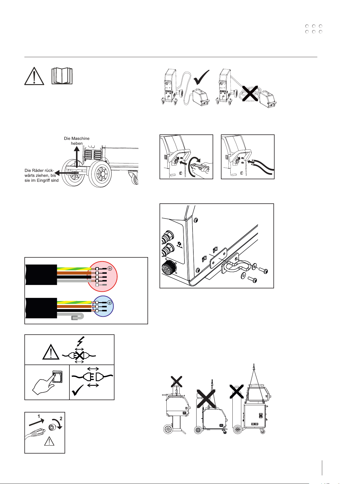
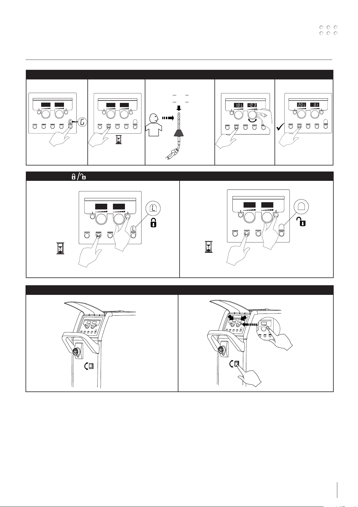
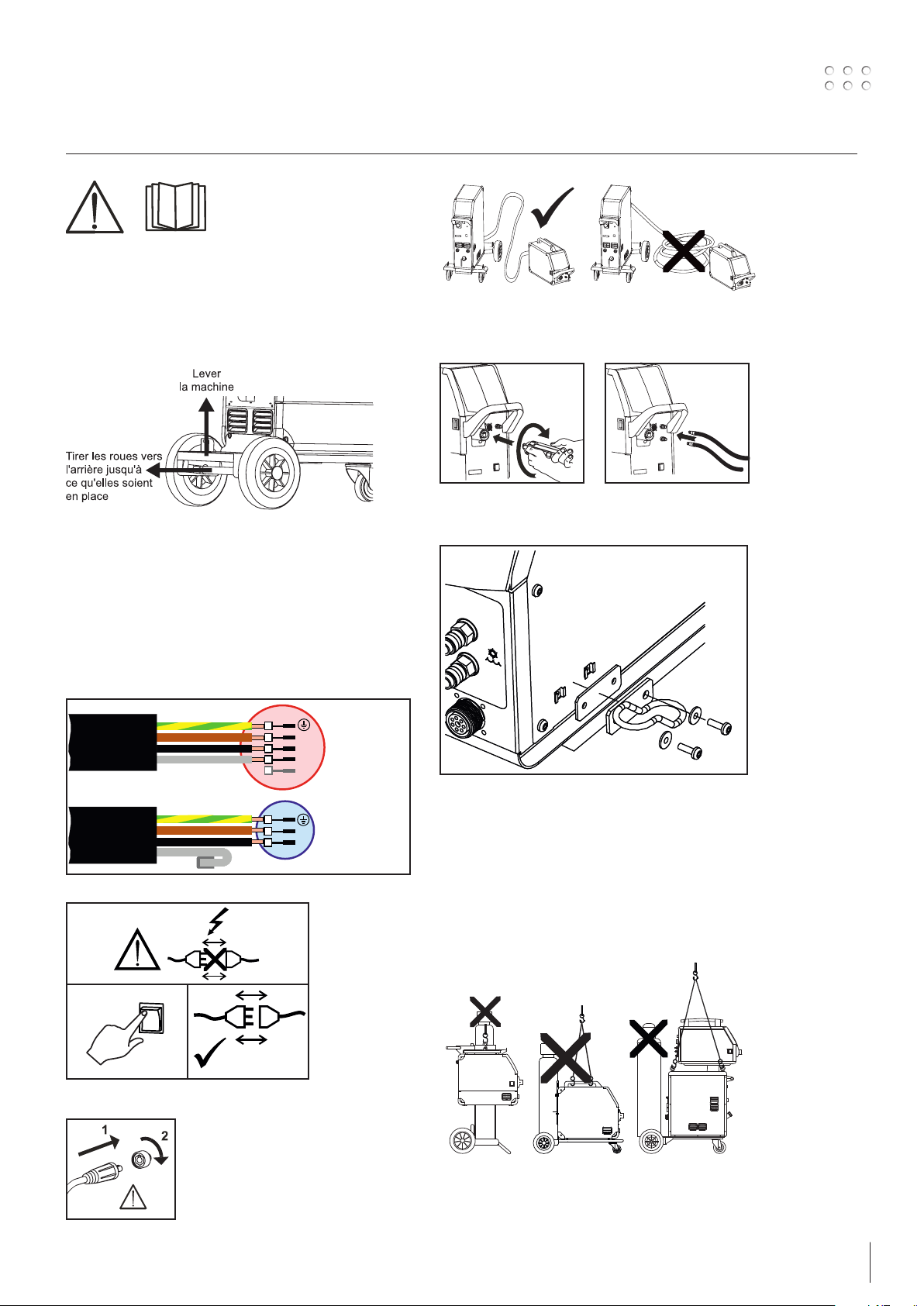
Tilslutning og ibrugtagning
Advarsel
Læs advarsel og brugsanvisning omhyggeligt
igennem inden installation
og ibrugtagning og gem
til senere brug.
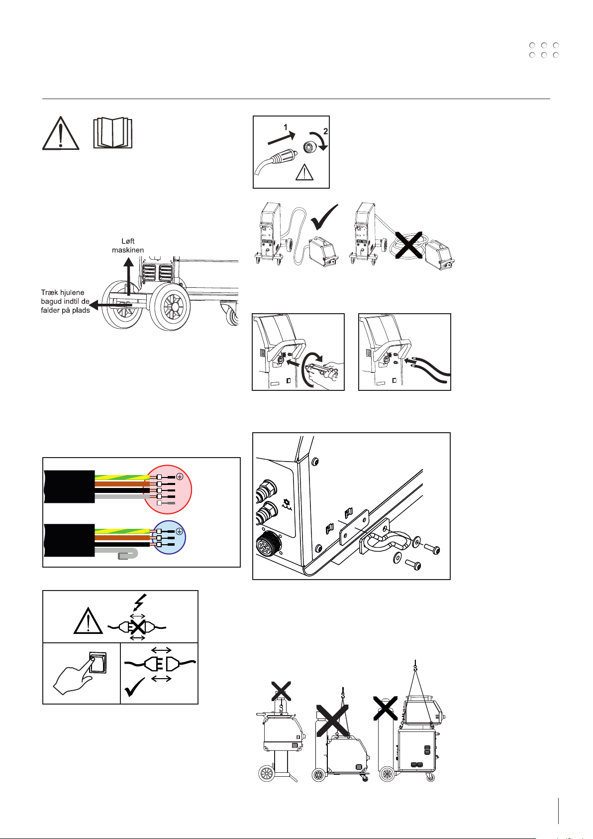
Udpakning af OMEGA2 C
Efter udpakning og før ibrugtagning gøres følgende
(se skitse)
Installation
Nettilslutning
Tilslut maskinen til den netspænding den er
konstrueret til. Se typeskiltet (U1) bag på maskinen.
Vigtigt!
Når stelkabel og svejseslange
tilsluttes maskinen, er god
elektrisk kontakt nødvendig,
for at undgå at stik og kabler
ødelægges.
Tilslutning af svejseslange
Montering af brænderholder
gul/grøn
brun
sort
gul/grøn
brun
sort
Grå
3x400V
3x230-400V (boost)
L1
grå
L2
L3
N
1x230-400V (boost)
L
N
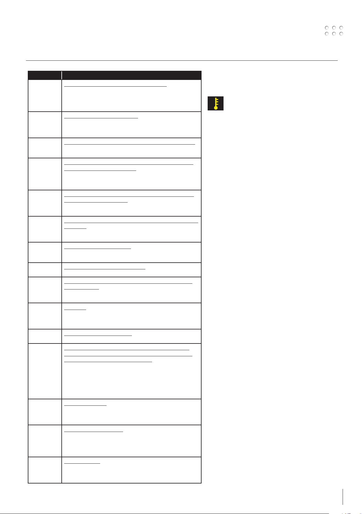
Løfteanvisning
Løftekroge kan bruges på OMEGA2 S og
OMEGA2 sækkevogn til løft med kran (figur 1 og 3).
OMEGA2 vogn med 4 hjul kan ikke løftes med kran,
men kun manuelt i håndtaget (figur 2).
Maskinen må ikke løftes med monteret gasflaske!
0
l
1
2
Fig. 1 Fig. 2 Fig. 3
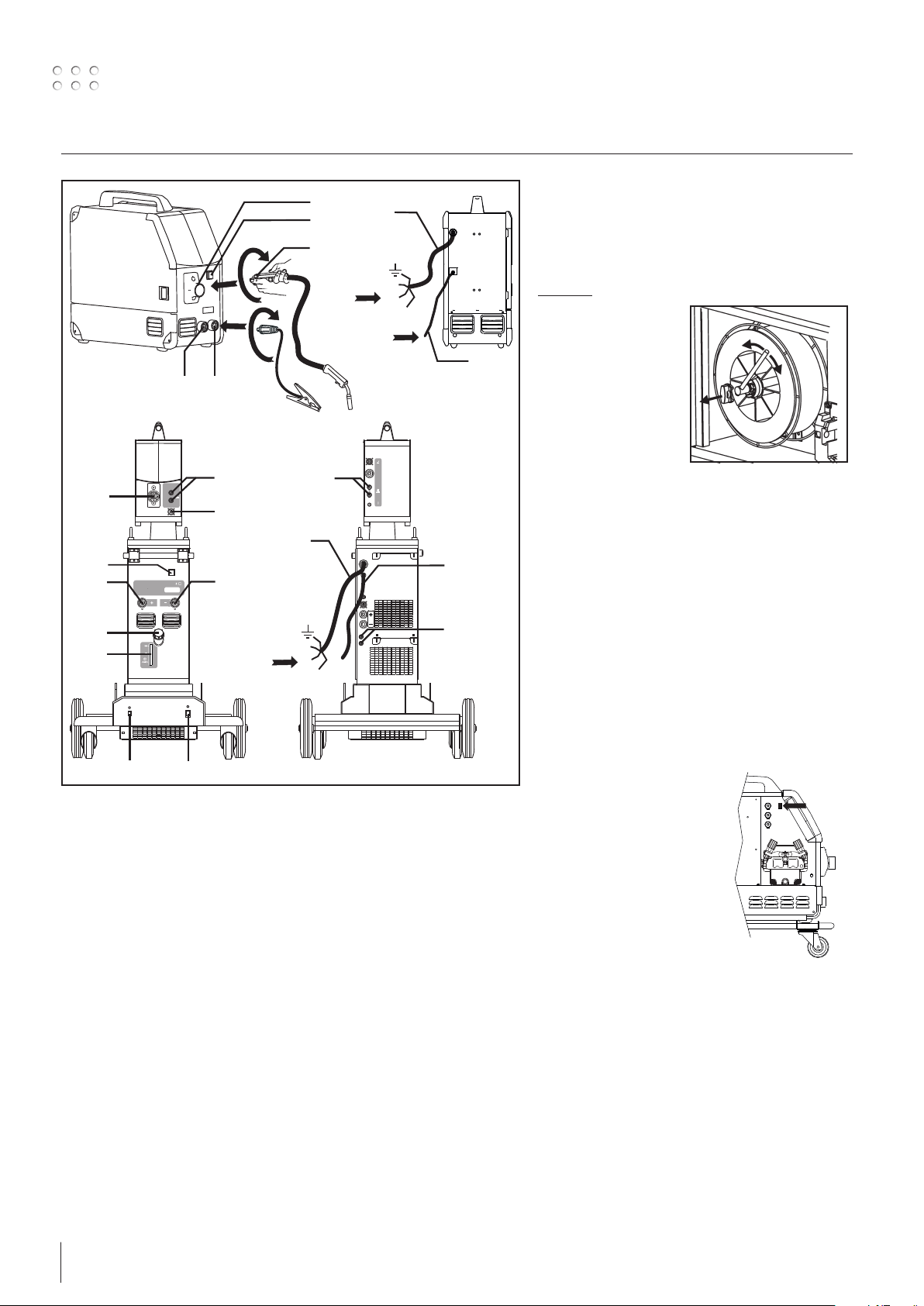
3
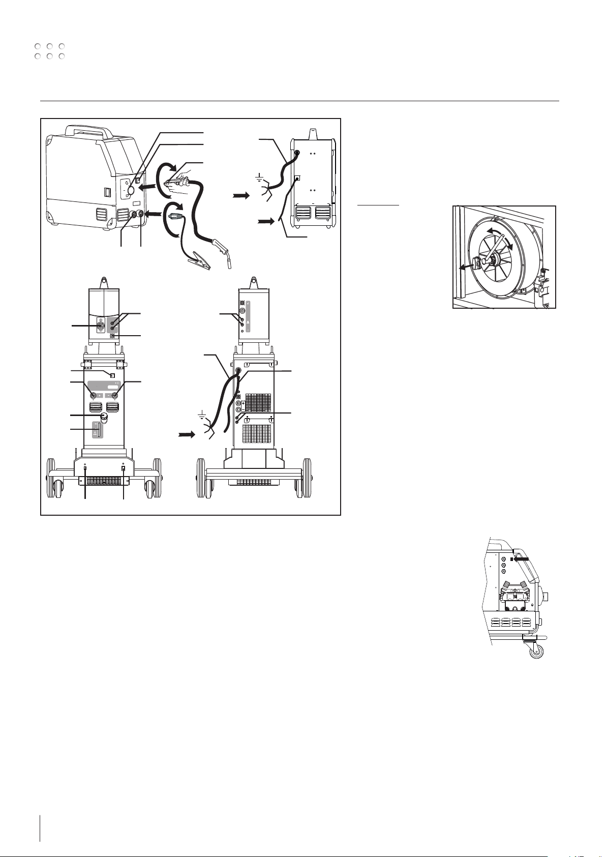
Tilslutning og ibrugtagning
10
4
2
5
Power
8
GAS
2-6 Bar
1
F
F
F
3
Justering af trådbremse
Bremsen justeres så stramt at trådrullen standser
inden svejsetråden kører ud over kanten på rullen.
Bremsekraften er afhængig af vægten på trådrullen, og trådhastigheden. Fabriksindstillet til 15kg.
Justering:
6 - 7
4
9
6 - 7
Max.5bar
1
2
13
8
Power
F
F
F
10
12
11
14
1. Nettilslutning
2. Tænd – sluk knap
3. Tilslutning beskyttelsesgas
4. Tilslutning - svejseslange
5. Svejseslange
6. Tilslutning for køleslanger
7. Tilslutning for køleslanger
8. Stelklemme (MIG) eller elektrodeholder-tilslutning
9. Tilslutning for Push-Pull svejseslange (ekstra udstyr)
10. Stelklemme (MMA) eller elektrodeholder-tilslutning
11. Aflæsning af kølevæskestand
12. Påfyldning af kølevæske
13. Tænd – sluk for autotrafo (ekstra udstyr)
14. Aktivering af autotrafo i standby (ekstra udstyr)
3
GAS
2-6 Bar
6 - 7
• Afmonter drejeknappen ved at stikke en tynd
skruetrækker ind bagved knappen og ryk
derefter knappen ud.
• Juster trådbremsen ved at spænde eller løsne
låsemøtrikken på trådnavets aksel.
• Monter drejeknappen igen.
Tilslutning af beskyttelsesgas
Gasslangen, som udgår fra bagsiden af maskinen
(3), tilsluttes en gasforsyning med en trykreduktion
til 2-6 bar. En gasflaske kan fikseres bag på eventuel
vogn.
Brænderregulering (Dialog brænder)
Hvis en svejseslange med Dialog brænder
anvendes, kan strømstyrke/trådhastighed justeres
både på maskinen og på dialog brænderen.
Brænderreguleringen er passiv uden Dialog
brænder.
Rangerfunktion
Funktionen bruges til at
rangere/fremføre tråd evt. efter
trådskift.
Fugebrænding (kun OMEGA2 550)
1. Monter fugebrændingstang.
2. Monter trykluftsslangen på kompressoren.
Indstil tryk mellem 5 og 7 bar.
3. Vælg MMA program.
Indstil maskinen til max. strømstyrke - ikke
under 400A.
4. Vælg kulelektrode (6-8 mm.)
5. Husk værnemidler: høreværn, svejsebriller,
handsker etc. og vær opmærksom på brandfare
fra metalgnister.
4
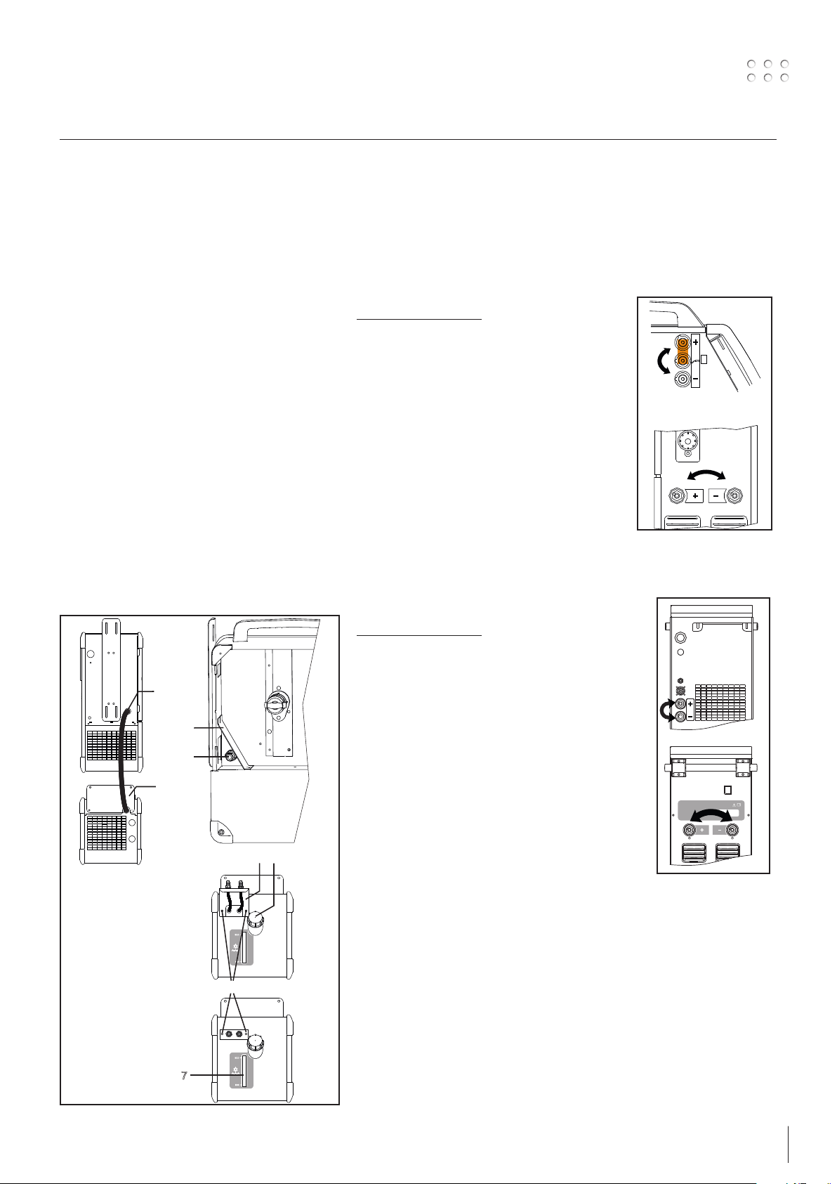
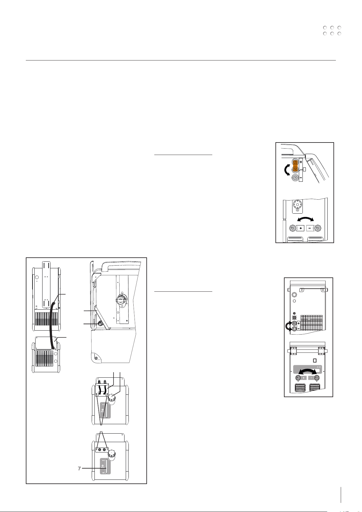
Tilslutning og ibrugtagning
1
Tilslutning af kølemodul
(OMEGA2 400/550 C)
1. Svejsemaskinen stilles oven på kølemodulet og
beslaget (1) monteres.
2. Strømkabel (2) trækkes ind igennem hullet i
bagende af maskinen. Beskyttelsesbeslaget (3) i
trådrummet afmonteres og det 4-polede stik (4)
sættes i. Monter beskyttelsesbeslaget igen.
3. Afmonter de 2 skruer (5) på beslaget med lynkoblingerne (6).
4. Beslaget trækkes ud og vendes så lynkoblingerne
vender opad og monteres igen med skruerne (5)
(se skitse).
5. Fremløbsslangen på den vandkølede svejseslange
monteres i den med blåt mærkede lynkobling,
mens tilbageløbsslangen monteres i den med
rødt mærkede lynkobling.
6. Vandstanden for kølevæske bør med jævne
mellemrum kontrolleres gennem vinduet (7).
7. Efterfyldning af kølevæske sker gennem
påfyldningsstudsen (8).
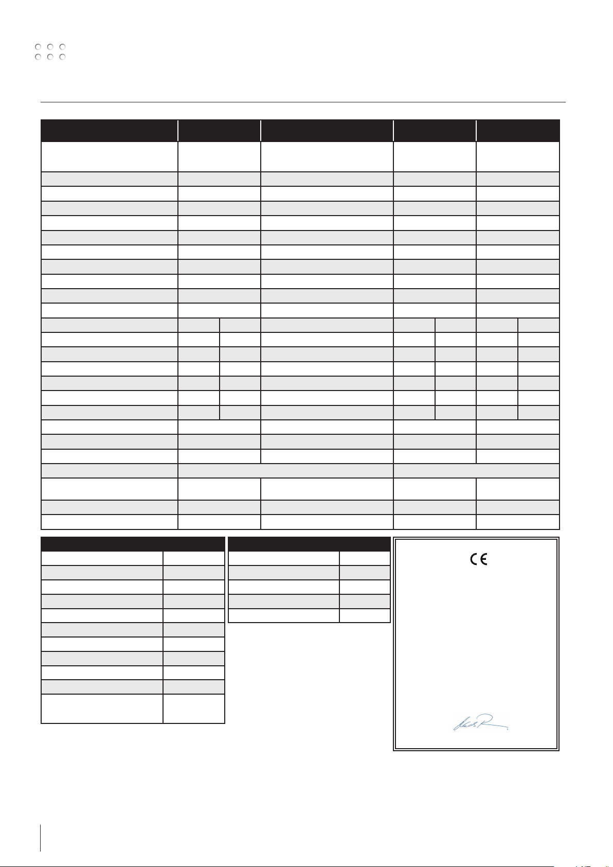
Valg af svejsepolaritet
For visse svejsetrådstyper anbefales det, at
man skifter svejsepolaritet. Det gælder især for
Innershield svejsetråd. Kontroller den anbefalede
polaritet på svejsetrådens emballage.
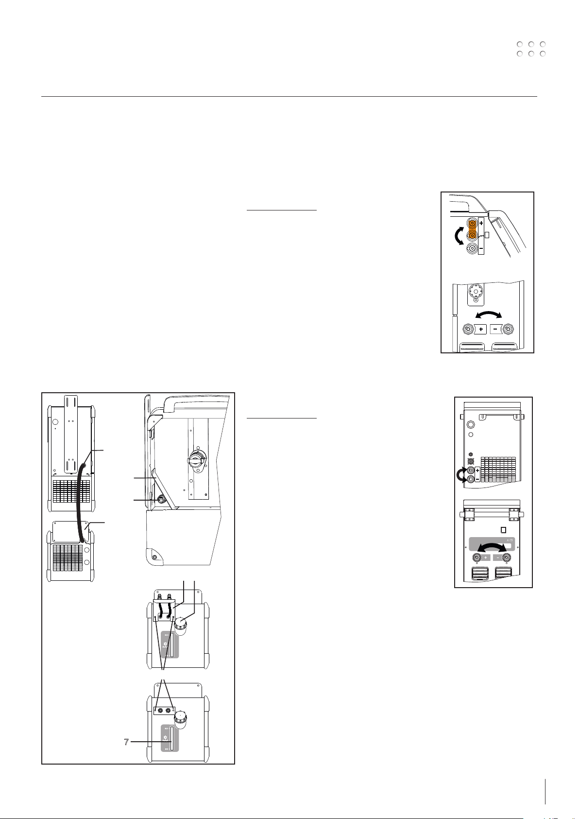
OMEGA2 C
Ændring af polaritet:
1. Afbryd maskinen fra lysnettet.
2. Afmonter skruerne i trådrummet med en nøgle
(fig. 1).
3. Flyt messingpladen fra plus til minus (fig. 1).
4. Monter skruerne i trådrummet med en nøgle
(fig. 1)
5. Flyt stelkabel fra minus til plus (fig. 2).
6. Slut maskinen til lysnettet.
2
Ændring af polaritet
OMEGA2 C
OMEGA2 S
Ændring af polaritet:
2
3
4
1
6
8
5
1. Afbryd maskinen fra lysnettet.
2. Flyt mellemkabel fra plus til minus
3. Flyt stelkabel fra minus til plus
4. Slut maskinen til lysnettet
2
Ændring af polaritet
OMEGA2 S
7
5

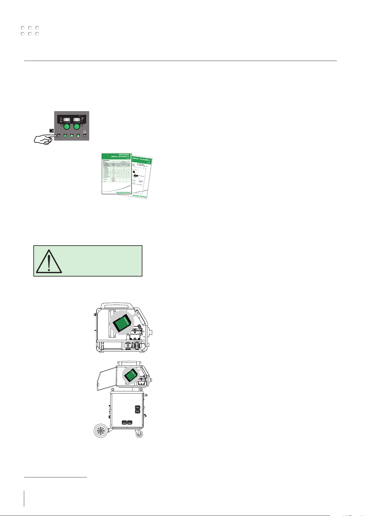
Tilslutning og ibrugtagning
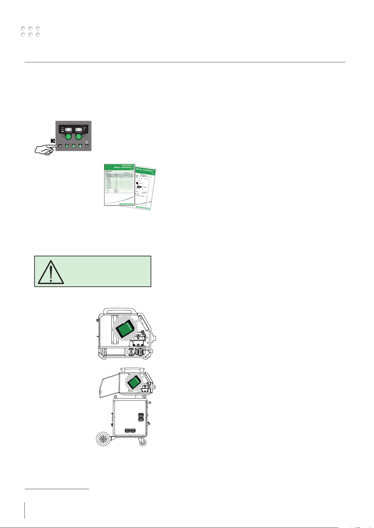
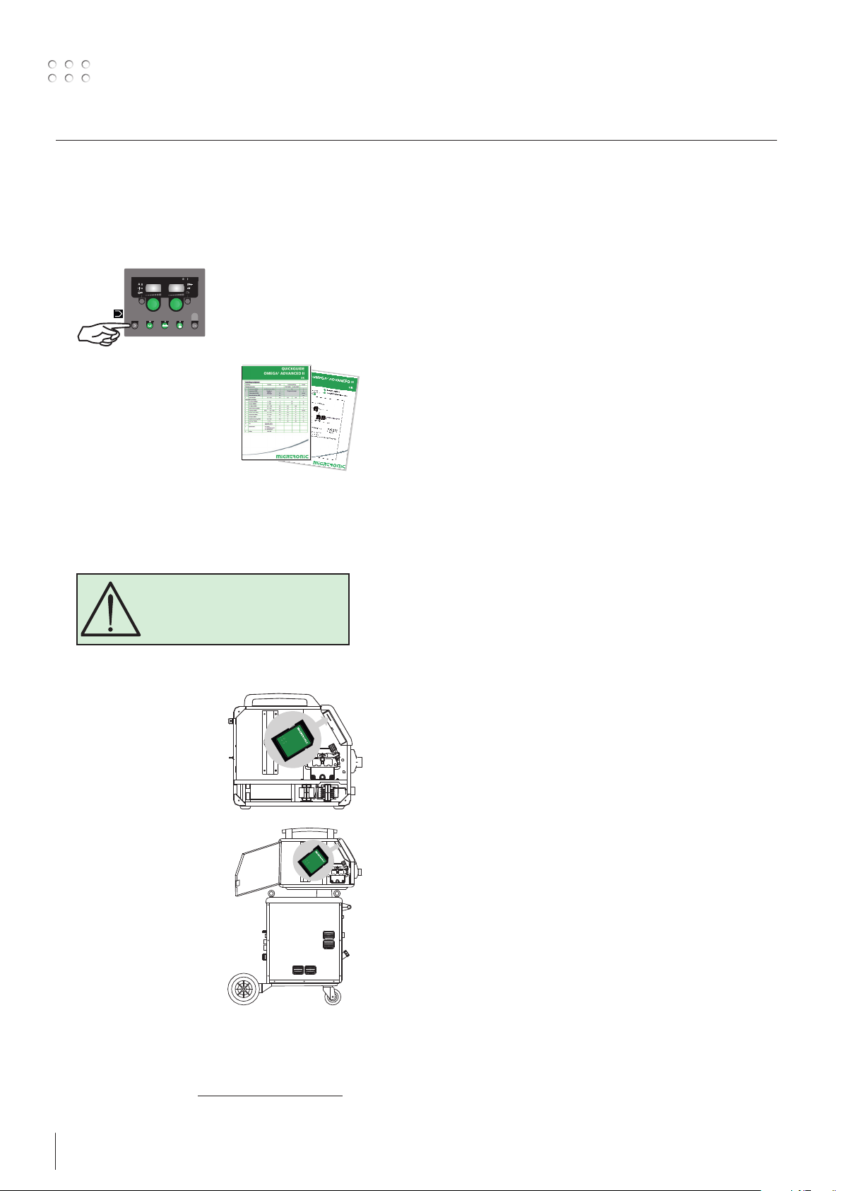
Tænd, tryk, svejs
Indstilling af svejseprogram
• Tænd svejsemaskinen på hovedafbryderen (2)
• Vælg svejseprogram eller materiale/gas/trådtyk-
SYNERGIC
ADVANCED II
mm
Se i Quickguide hvordan det
vælges for din svejsemaskine.
Vælg den indstilling som
passer til den svejsetråd og
beskyttelsesgas, der skal
svejses med.
• Indstil svejsestrøm og sekundære parametre
Se Quickguide
kelse. (Afhængig af
model)
• Maskinen er nu klar til at svejse
ADVARSEL
Når der trykkes på svejseslangens
kontakt/tast er der spænding på
svejsetråden.
Software indlæsning
• Indsæt SD-kortet i maskinens kortlæser som vist
på tegningerne.
• Tænd maskinen.
• Displayet blinker kortvarigt med tre streger
• Vent indtil maskinens
display viser den
indstillede strøm.
• Sluk maskinen og tag SDkortet ud.
• Maskinen er nu klar til
brug.
Hvis kontrolboksen udskiftes er det nødvendigt at
lægge software ind i den nye boks igen, ved hjælp af et
SD kort. Softwaren kan downloades fra
http://migatronic.com/login
6
Specielle funktioner
5 SECS
L
L
5 SECS
5 SECS
Kalibrering af gasflow (ikke alle modeller)
I II III
IV V
10
10
min
min
=
L
L
20
20
=
min
min
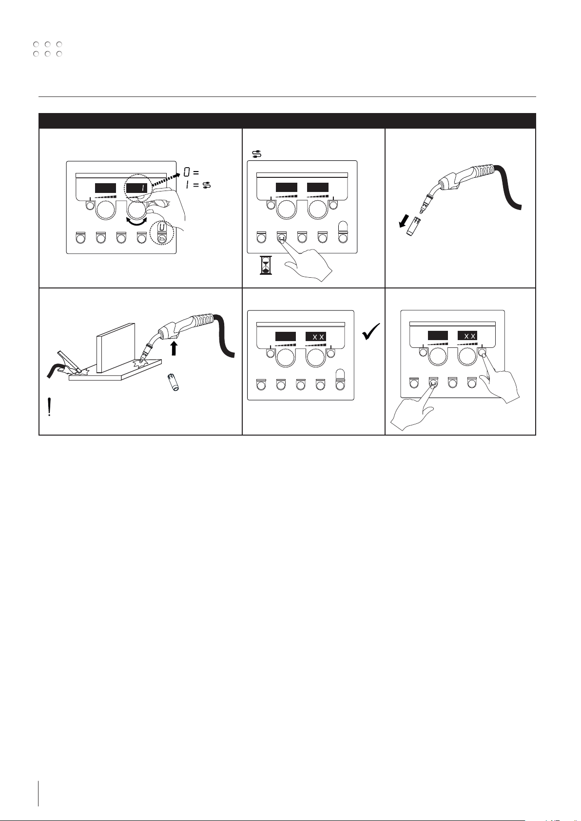
1
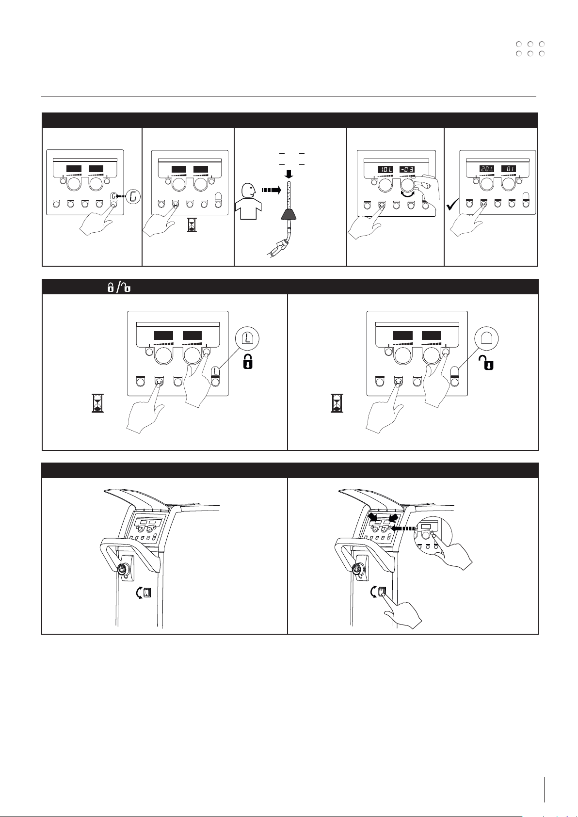
Låsefunktion
I II
Visning af softwareversioner
I II
Flowmeter
No.: 81010000
2
1
2
OFF
ON
7

Tilslutning og ibrugtagning
Std.
5 SECS
Kabelkompensering (kalibrering af modstand i svejseslange)
I
IV V VI
II
Factor
III
2
Svejseemnets overflade skal være ren for
at sikre god kontakt med brænderen.
1
8
Fejlfinding og udbedring
Fejlkode Årsag og udbedring
E20-00
E20-02
E21-00
E21-06
E21-08
E20-01
E21-01
E20-03
E21-02
E20-04 Kontrolboksen har forsøgt at indlæse flere data
E20-05
E20-06
E20-07 Den interne kopibeskyttelse tillader ikke adgang til
E20-08
E20-09
E21-05
E20-10
E21-07
E21-03
E21-04
Err GAS Gasfejl
E02-04 CAN – kommunikationsfejl
Err H2O Kølefejl vises på maskiner med monteret vandflow-
E11-20 Strømsensorfejl
E11-28 Fase/spændingsfejl
E11-42 Probespænding
Der er ingen software i kontrolboksen
Download Omega software til SD-kortet, sæt SD
kortet i boksen og tænd maskinen. Udskift evt.
SD-kortet.
SD kortet er ikke formateret
Formater SD-kortet i en PC som FAT og download
Omega software til SD-kortet. Udskift evt. SDkortet.
SD-kortet har flere filer med samme navn
Slet SD-kortet og download software igen.
end den kan have i hukommelsen
Indlæs SD-kortet igen eller udskift SD-kortet. Tilkald
MIGATRONIC Service, hvis problemet ikke løses.
Software på SD-kortet er låst til en anden type
kontrolboks
Anvend et SD-kort med software som passer til din
type kontrolboks.
mikroprocessoren
Indlæs SD-kortet i maskinen igen eller tilkald
MIGATRONIC Service.
Kontrolboksen er defekt
Tilkald MIGATRONIC Service.
Den indlæste fil er fejlbehæftet
Indlæs SD-kortet igen eller udskift SD-kortet.
Den indlæste svejseprogrampakke passer ikke til
kontrolboksen
Anvend et SD-kort med software som passer til din
kontrolboks.
Kontroller gastilførslen.
Gasfejl afmeldes med et kort tryk på en vilkårlig
tast.
Check mellemkabel/stik
kit, i tilfælde af at kølevandet ikke kan cirkulere
som følge af forkert tilslutning eller tilstopning.
Kontroller at køleslangerne er korrekt tilsluttet,
efterfyld vandbeholderen og efterse svejseslange
og tilslutningsstudser.
Kølefejl afmeldes med et kort tryk på en vilkårlig
tast.
1. Check strømsensor
2. Tilkald MIGATRONIC service
1. Check alle 3 faser
2. Check for underspænding
3. Tilkald MIGATRONIC service
1. Check om svejsetråden er brændt fast
2. Tilkald MIGATRONIC service
Fejlsymboler
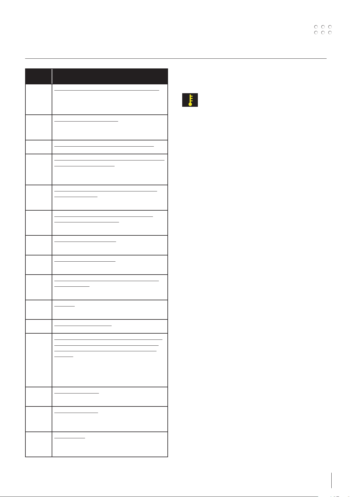
Temperaturfejl:
Overophedningsindikatoren lyser, hvis
svejsningen er blev afbrudt på grund af
overophedning af maskinen.
Lad maskinen være tændt, indtil den er afkølet af
den indbyggede blæser.
9
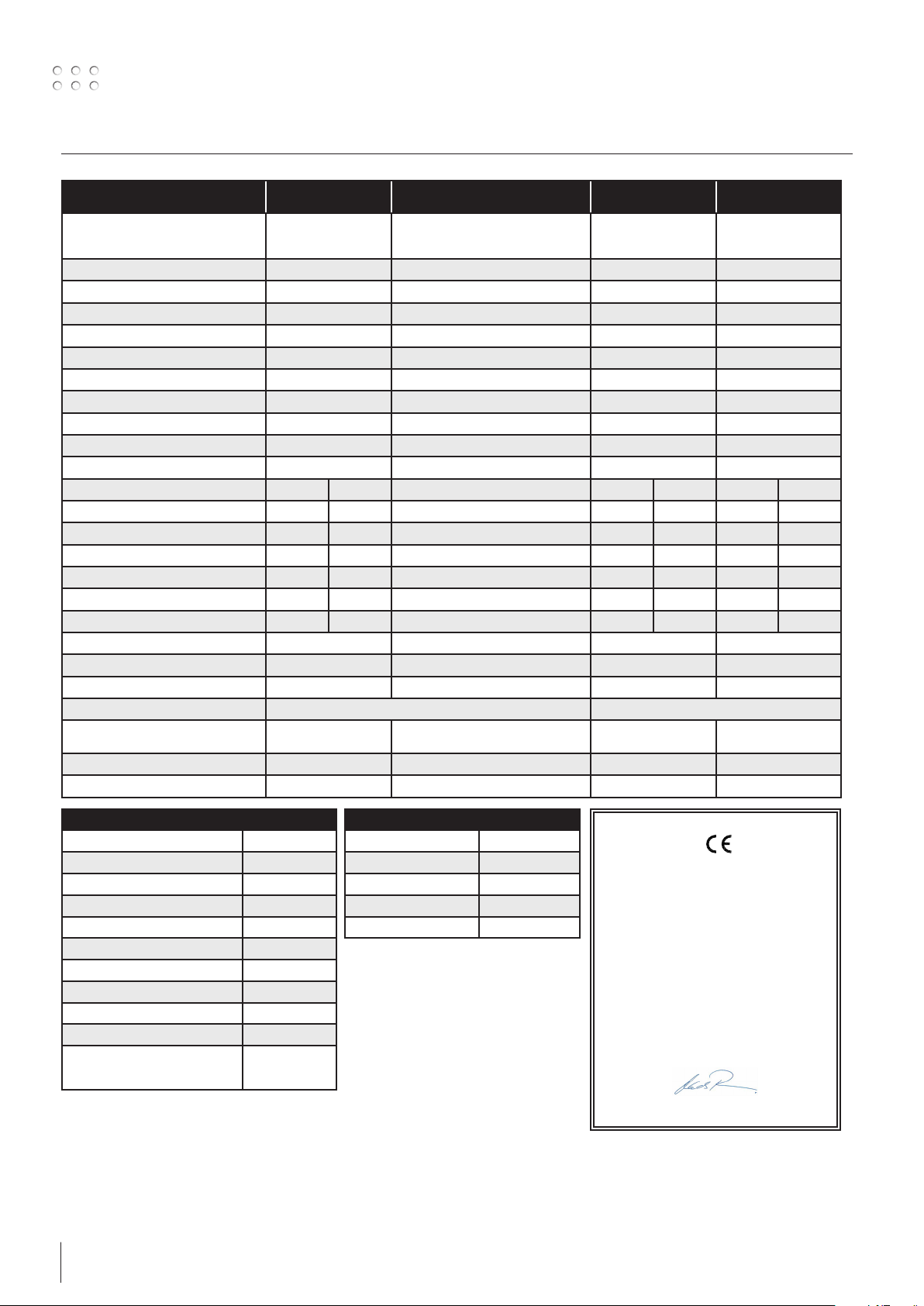
Tekniske data
STRØMKILDE OMEGA
Netspænding ±15% (50-60Hz), V
- Autotrafo tilbehør ±15% (50-60Hz), V
300
3x400
-
2
2
OMEGA
300 Boost
3x230-400, 1x230-400
-
OMEGA2
400
3x400
3x230-500
OMEGA2
550
3x400
3x230-500
Minimum generatorstørrelse, kVA 17 15,5 (1x230), 16,5 (3x230), 15,5 (3x400) 27 40
1
Minimum kortslutningseffekt Ssc, MVA 0,8 (1x230), 2,1 (3x230), 2,1 (3x400) 4,0 5,74
Netsikring, A 10 16 20 35
Netstrøm, effektiv, A 9,0 11,9 (1x230), 7,0 (3x230), 3,1 (3x400) 17,5 27,3
Netstrøm, max., A 16,9 45,3 (1x230), 26,7 (3x230), 15,0 (3x400) 26,0 39,2
Effekt, (100%), kVA 6,3 2,7 (1x230), 3,8 (3x230), 3,5 (3x400) 12,1 18,9
Effekt, max, kVA 11,5 10,4 (1x230), 11,0 (3x230), 10,3 (3x400) 18,0 27,1
Effekt, tomgang, W 20 30 40 30
Virkningsgrad 0,88 0,84(1x230), 0,84 (3x230), 0,87 (3x400) 0,85 0,91
Power faktor 0,93 0,99 (1x230), 0,95 (3x230), 0,95 (3x400) 0,94 0,94
MIG MMA MIG MMA MIG MMA
Intermittens 100% v/20°C, A/V 230/25,5 - 170 (1x230) 200 (3x400) 335 335 475 475
Intermittens 60% v/20°C, A/V 245/26,3 - 220/25 (1x230) 235/25,7 (3x400) 400 400 550 550
Intermittens 100% v/40°C, A/V 175/22,8 175/27 110/19,1 (1x230) 135/21,0 (3x400) 300/29,0 300/32,0 430/35,5 430/37,2
Intermittens 60% v/40°C, A/V 195/23,8 195/27,8 135/20,8 (1x230) 170/22,5 (3x400) 370/32,5 350/34,6 510/39,5 510/40,4
Intermittens max. v/40°C, A/%/V 300/24/29,0 300/20/32 300/15/29,3 (1x230) 300/24/28,9 (3x400) 400/50/34,0 400/45/36,0 550/50/41,5 550/50/42,0
Strømområde, A 15-300 0 - 300 15-300 15-400 15-400 15-550 15-550
Tomgangsspænding, V 52 55 70 80
2
Anvendelsesklasse S/CE S/CE S/CE S/CE
3
Beskyttelsesklasse IP23 IP23 IP23 IP23
Normer EN/IEC60974-1, EN/IEC60974-5, EN/IEC60974-10 EN/IEC60974-1, EN/IEC60974-5 (C), EN/IEC60974-10,
Dimensioner (HxBxL), mm 550x250x640 550x250x640 530x250x650 (C) /
1400x510x1020 (S)
630x250x650 (C) /
1400x510x1020 (S)
Vægt, kg 26 28 36,5 (C) / 84 (S) 37,5 (C) / 85 (S)
Trådfremføringshastighed, m/min 1,5-18 1,5-18,0 0,5-27,0 0,5-27,0
TRÅDBOKS MWF 27
Trådfremføringshastighed, m/min 0,5-27,0
Brændertilslutning EURO
Trådspolediameter, mm 300
100% intermittens, 40°C, A/% 430/100
Max. intermittens, 40°C, A/% 550/50
Tråddiameter, mm 0,6-2,4
3)
Beskyttelsesklasse IP23
Gastryk max., MPa (bar) 0,5 (5,0)
Dimensioner (HxBxL), mm 470x210x690
Vægt, kg 13
Normer EN/IEC660974-1,
1) Dette udstyr er i overensstemmelse med IEC 61000-3-12, forudsat at nettets kortslutnings-effekt Ssc ved tilslutningsstedet er større end eller lig med de opgivne
data i ovenstående skema. Installatøren eller brugeren af udstyret er ansvarlig for at sikre, evt. i samråd med forsyningsdistributøren, at udstyret er tilsluttet til en
netforsyning med en kortslutnings-effekt Ssc større end eller lig med de opgivne data i ovenstående skema.
2
KØLEMODUL
EU-OVERENSSTEMMELSESERKLÆRING
Køleeffekt, W 1100
EN/IEC660974-5,
EN/IEC660974-10
Tankkapacitet, liter 3,5
Flow, bar - °C - l/min 1,2 - 60 - 1,75
Maks. tryk, bar 3
Normer EN/IEC60974-2
MIGATRONIC A/S
Aggersundvej 33
9690 Fjerritslev
Danmark
erklærer, at nedennævnte maskine
Type: OMEGA2
fra uge 02 2013
er i overensstemmelse med bestemmelserne i
direktiverne 2014/35/EU
2014/30/EU
2011/65/EU
Europæiske EN/IEC60974-1
standarder: EN/IEC60974-5
EN/IEC60974-10 (Class A)
Udfærdiget i Fjerritslev 20.04.2016
Mads Prebensen
CEO
2) S Maskiner opfylder de krav der stilles under anvendelse i områder med forøget risiko for elektrisk chok
3) Angiver at maskinen er beregnet for såvel indendørs som udendørs anvendelse
10
Connection and start-up
2
Warning
Read warning notice and
instruction manual carefully prior
to initial operation and save the
information for later use.
Unpacking the OMEGA2 C
After unpacking and prior to use, proceed as follows (see
drawing):
Connection of welding hose
Fastening the torch holder
Permissible installation
Mains connection
Connect the machine to the correct mains supply. Please
read the type plate (U1) on the rear side of the machine.
3x400V
yellow/green
brown
black
grey
yellow/green
brown
black
grey
0
l
3x230-400V (boost)
L1
L2
L3
N
1x230-400V (boost)
L
N
Lifting instructions
Lifting hooks can be used at the OMEGA2S and the
OMEGA2 sack barrow for lifting with a crane (figures 1 and
3).
The OMEGA2 trolley with four wheels cannot be lifted with
a crane but only manually using the handle (figure 2).
The machine must not be lifted with a mounted gas
cylinder!
1
Important!
In order to avoid destruction of plugs
and cables, good electric contact
is required when connecting earth
cables and welding hoses to the
machine.
Fig. 1 Fig. 2 Fig. 3
11

Connection and start-up
10
12
11
4
2
5
Power
10
8
6 - 7
4
9
2
8
Power
6 - 7
1
F
F
F
GAS
2-6 Bar
Max.5bar
1
F
F
F
3
GAS
2-6 Bar
6 - 7
Adjustment of wire brake
The wire brake must ensure that the wire reel brakes
sufficiently before the welding wire runs over the
edge of the reel.
The brake force is dependent on the weight of the
wire reel and wire feed speed.
Factory setting is 15kg.
Adjustment:
• Dismount the
control knob by
3
placing a thin
screw driver behind
the knob and
thereafter pull it
out.
• Adjust the wire
brake by fastening
or loosening the self-locking nut on the axle of
the wire hub.
• Remount the control knob.
Connection of shielding gas
The shielding gas hose is fitted to the back panel
of the power source (3) and is connected to a gas
supply with a pressure reduction to 2-6 bar. One gas
cylinder can be mounted on the bottle carrier on the
back of a trolley if any.
Torch adjustment (Dialog torch)
The current size/wire feed speed can be adjusted
both from the machine and the welding torch if a
welding hose with dialog torch is in use. The torch
adjustment is passive without Dialog torch.
14
1. Mains connection
2. Power switch
3. Connection of shielding gas
4. Connection of welding hose
5. Welding hose
6. Connection of cooling hoses
7. Connection of cooling hoses
8. Connection of earth clamp (MIG) or electrode holder
9. Connection of push-pull welding hose (option)
10. Connection of earth clamp (MMA) or electrode holder
11. Cooling liquid level control
12. Refill of cooling liquid
13. Power switch for autotransformer (optional)
14. Activation of autotransformer in standby (optional)
13
Inching
The function is used for wire
inching e.g. after change of
wire.
Gouging (only OMEGA2 550)
1. Mount the carbon-arc torch
2. Mount the compressed air hose on the
compressor. Set the pressure between 5 and
7bar
3. Select MMA program. Set the machine at
max. current – not less than 400A
4. Select carbon electrode (6-8 mm)
5. Use protective equipment: ear protection,
welding goggles, gloves etc. Note! Metal sparks
pose fire danger.
12
Connection and start-up
1
Connection of a water
cooling unit
(OMEGA2 400/550 C)
1. Place the welding machine on top of the cooling
unit and mount the fitting (1).
2. Pull the power cable (2) through the hole on
the rear side of the machine. Dismount the
protection fitting (3) in the wire chamber
and insert the 4-pole plug (4). Remount the
protection fitting.
3. Dismount the two screws (5) on the fitting with
the quick connections (6).
4. Pull out and turn the fitting so that the quick
connections turn up. Then remount the fitting
with the screws (5) (see drawing).
5. Mount the flow hose on the water-cooled torch
in the quick connection marked blue and the
return hose in the quick connection marked red.
6. The cooling liquid level should be inspected
regularly by means of the level control (7).
7. Refill of cooling liquid takes place through the
filler neck (8).
2
3
Selecting welding polarity
Polarity reversal is recommended for certain types
of welding wire, in particular Innershield welding
wire. For recommended polarity, please refer to the
welding wire packaging.
OMEGA2 C
Change of polarity:
1. Disconnect the machine from the mains supply.
2. Dismount screws in the wire chamber with a
wrench (picture 1).
3. Exchange brass plate from plus to minus
(picture1).
4. Mount screws in the wire chamber with a
wrench (picture 1).
5. Exchange earth cable from minus to plus
(picture2).
6. Connect the machine to the mains supply.
OMEGA2 S
Change of polarity:
1. Disconnect the machine from the mains supply.
2. Exchange intermediary cable from plus to minus.
3. Exchange earth cable from minus to plus.
4. Connect the machine to the mains supply.
2
Change of polarity
OMEGA2 C
4
1
2
6
8
Change of polarity
OMEGA2 S
5
7
13
Connection and start-up
Switch on, press, weld
Welding program setting
• Switch on the welding machine on the main switch
(2)
• Select welding program or material/gas/wire
SYNERGIC
ADVANCED II
mm
Please read how this should
be selected on your welding
machine in the quick guide.
Select the setting that fits the
required wire and shielding
gas.
• Adjust the welding current and secondary
parameters. Please read your quickguide
dimension. (Depending
on the model).
• The machine is now ready to weld
WARNING
Voltage is present on the welding
wire when pressing the welding
hose trigger.
Software reading
• Insert the SD card into
the machine’s card
reader as shown in the
drawings.
• Turn on the machine.
• The display flashes
shortly with three lines
• Wait until the set current
is displayed.
• Turn off the machine and
remove the SD card.
• The machine is now
ready for use.
It is necessary to read software inside the new control
unit by means of a SD card, if the control unit has been
exchanged. The software can be downloaded from
http://migatronic.com/login
14

Special functions
5 SECS
5 SECS
5 SECS
L
L
Calibration of gas flow (not all models)
I II III
IV V
10
10
min
min
=
L
L
20
20
=
min
min
1
Lock function
I II
Display of software versions
I II
Flowmeter
No.: 81010000
2
1
2
OFF
ON
15

Special functions
Std.
5 SECS
Cable compensation (calibration of resistance in welding hose)
I
IV V VI
II
Factor
III
2
The surface of the workpiece must be clean
to ensure good contact with the torch.
1
16
Troubleshooting Guide
Error
Cause and solution
code
E20-00
E20-02
E21-00
E21-06
E21-08
E20-01
E21-01
E20-03
E21-02
E20-04 The control unit has tried to read more data than
E20-05
E20-06
E20-07 The internal copy protection does not allow
E20-08
E20-09
E21-05
E20-10
E21-07
E21-03
E21-04
Err GAS Gas error
E02-04 CAN communication error
Err H2O Cooling fault is indicated on machines equipped
E11-20 Current sensor error
E11-28 Phase/voltage error
E11-42 Probe voltage
There is no software present in the control unit
Download Omega software to the SD card, insert
the SD card in the control unit and turn on the
machine. Replace the SD card if necessary.
The SD card is not formatted
The SD card must be formatted in a PC as FAT
and download Omega software to the SD card.
Replace the SD card if necessary.
The SD card has more files of the same name
Delete files on the SD card and reload software.
is accessible in the memory
Insert the SD card again or replace the SD card.
Contact MIGATRONIC Service if this does not solve
the problem.
Software on the SD card is locked for another
type of control unit
Use a SD card with software that matches your
control unit.
access to the micro-processor
Insert the SD card in the machine again or contact
MIGATRONIC Service.
The control unit is defective
Contact MIGATRONIC Service
The loaded file has an error
Insert the SD card in the machine again or replace
the SD card.
The welding program package does not match
this control unit
Use a SD card with software that matches your
control unit.
Check the gas supply.
Cancel the gas fault by briefly pressing any key.
Check intermediary cable/plug
with water flow kit in case of no circulation of
the cooling liquid due to faulty connection or
choking.
Check that the cooling hoses are correctly
connected, top up the water tank and check
welding hose and branches.
Cancel the cooling fault by briefly pressing any
key.
1. Check the current sensor
2. Contact MIGATRONIC service
1. Check all three phases
2. Check for under-voltage
3. Contact MIGATRONIC service
1. Check if welding wire is sticking in the weld
pool
2. Contact MIGATRONIC service
Fault symbols
Temperature fault:
The indicator is switched on, when the
power source is overheated.
Leave the machine on until the built-in fan has
cooled it down.
17
Technical data
POWER SOURCE OMEGA
Mains voltage ±15% (50-60Hz), V
300
3x400
2
2
OMEGA
300 Boost
3x230-400. 1x230-400
OMEGA2
400
3x400
OMEGA2
550
3x400
- Autotransformer
optional ±15% (50-60Hz), V
-
-
3x230-500
3x230-500
Minimum generator size, kVA 17 15.5 (1x230). 16.5 (3x230). 15.5 (3x400) 27 40
1
Minimum short-circuit power Ssc, MVA 0.8 (1x230). 2.1 (3x230). 2.1 (3x400) 4.0 5.74
Fuse, A 10 16 20 35
Mains current, effective, A 9.0 11.9 (1x230). 7.0 (3x230). 3.1 (3x400) 17.5 27.3
Mains current, max., A 16.9 45.3 (1x230). 26.7 (3x230). 15.0 (3x400) 26.0 39.2
Power, (100%), kVA 6.3 2.7 (1x230). 3.8 (3x230). 3.5 (3x400) 12.1 18.9
Power, max., kVA 11.5 10.4 (1x230). 11.0 (3x230). 10.3 (3x400) 18.0 27.1
Power, open circuit, W 20 30 40 30
Efficiency 0.88 0.84(1x230). 0.84 (3x230). 0.87 (3x400) 0.85 0.91
Power faktor 0.93 0.99 (1x230). 0.95 (3x230). 0.95 (3x400) 0.94 0.94
MIG MMA MIG MMA MIG MMA
Duty cycle 100% 20°C, A/V 230/25.5 - 170 (1x230) 200 (3x400) 335 335 475 475
Duty cycle 60% 20°C, A/V 245/26.3 - 220/25 (1x230) 235/25.7 (3x400) 400 400 550 550
Duty cycle 100% 40°C, A/V 175/22.8 175/27 110/19.1 (1x230) 135/21.0 (3x400) 300/29.0 300/32.0 430/35.5 430/37.2
Duty cycle 60% 40°C, A/V 195/23.8 195/27.8 135/20.8 (1x230) 170/22.5 (3x400) 370/32.5 350/34.6 510/39.5 510/40.4
Duty cycle max. 40°C, A/%/V 300/24/29.0 300/20/32 300/15/29.3 (1x230) 300/24/28.9 (3x400) 400/50/34.0 400/45/36.0 550/50/41.5 550/50/42.0
Current range, A 15-300 0 - 300
15-300 15-400 15-400 15-550 15-550
Open circuit voltage, V 52 55 70 80
2
Sphere of application S/CE S/CE S/CE S/CE
3
Protection class IP23 IP23 IP23 IP23
Standards EN/IEC60974-1. EN/IEC60974-5. EN/IEC60974-10 EN/IEC60974-1. EN/IEC60974-5 (C). EN/IEC60974-10.
Dimensions (HxWxL), mm 550x250x640 550x250x640 530x250x650 (C) /
1400x510x1020 (S)
630x250x650 (C) /
1400x510x1020 (S)
Weight, kg 26 28 36.5 (C) / 84 (S) 37.5 (C) / 85 (S)
Wire feed speed, m/min 1.5-18 1.5-18.0 0.5-27.0 0.5-27.0
WIRE FEED UNIT MWF 27
Wire feed speed, m/min 0.5-27.0
Torch connection EURO
Wire-reel diameter, mm 300
100% duty cycle 40°C, A/% 430/100
Max. duty cycle, 40°C, A/% 550/50
Wire diameter, mm 0.6-2.4
3)
Protection class IP23
Gas pressure max., MPa (bar) 0.5 (5.0)
Dimensions (HxWxL), mm 470x210x690
Weight, kg 13
Standards EN/IEC660974-1.
1) This equipment complies with IEC 61000-3-12 provided that the short-circuit power Ssc of the grid at the interface point is greater than or equal to the stated data
in the abovementioned table. It is the responsibility of the installer or user of the equipment to ensure, by consultation with the distribution network operator if
necessary, that the equipment is connected only to a supply with a short-circuit power Ssc greater than or equal to the stated data in the abovementioned table.
2
COOLING UNIT
EC DECLARATION OF CONFORMITY
Cooling efficiency, W 1100
EN/IEC660974-5.
EN/IEC660974-10
Tank capacity, liter 3.5
Flow, bar - °C - l/min 1.2 - 60 - 1.75
Pressure max., bar 3
Standards EN/IEC60974-2
MIGATRONIC A/S
Aggersundvej 33
9690 Fjerritslev
Denmark
hereby declare that our machine as stated below
Type: OMEGA2
As of week 02 2013
conforms to directives: 2014/35/EU
2014/30/EU
2011/65/EU
European standards: EN/IEC60974-1
EN/IEC60974-5
EN/IEC60974-10 (Class A)
Issued in Fjerritslev 20.04.2016
Mads Prebensen
CEO
2) S This machine meets the demand made for machines which are to operate in areas with increased hazard of electric chocks
3) Equipment marked IP23 is designed for indoor and outdoor applications
18
Anschluss und Inbetriebnahme
2
Warnung
Lesen Sie die Warnhinweise und
Betriebsanleitung sorgfältig vor
der Inbetriebnahme und speichern
Sie die Information für den
späteren Gebrauch.
Auspacken der OMEGA2 C
Nach Auspacken und vor Gebrauch, wie folgt vorgehen
(siehe Zeichnung):
Anschluß der Schweißschlauch
Befestigung des Brennerhalters
Zulässige Installation
Netzanschluss
Die Maschine soll an eine Netzspannung angekuppelt
werden, die mit den Angaben auf dem Typenschild (U1)
hinter die Maschine übereinstimmt.
3x400V
gelb/grün
braun
schwarz
grau
gelb/grün
braun
schwarz
grau
0
l
3x230-400V (boost)
L1
L2
L3
N
1x230-400V (boost)
L
N
Hebeanweisung
Hebehaken können an die OMEGA2S und den OMEGA2
Sackkarren zum Heben mit Kran angeschlossen werden
(Figur 1 und 3).
Der OMEGA2 Wagen mit 4 Rädern kann nicht mit Kran,
sondern nur manuell im Handgriff angehoben werden
(Figur 2).
Die Maschine darf nicht mit montierter Gasflasche
angehoben werden!
1
Wichtig!
Achten Sie auf festen Sitz der
Anschlüsse von Massekabel und
Schweißschlauch.
Die Stecker und Kabel können sonst
beschädigt werden.
Fig. 1 Fig. 2 Fig. 3
19
Anschluss und Inbetriebnahme
Justierung der Drahtbremse
Die Bremse wird so fest eingestellt, daß die Drahtrolle stoppt, ehe der Schweißdraht über den Rand
läuft.
Die Bremsekraft ist vom Gewicht der Drahtrolle und
der Drahtfördergeschwindigkeit abhängig.
Werkeinstellung = 15kg.
Justierung:
• Der Drehknopf
kann abmontiert
werden, wenn
ein Schraubendreher hinter den
Knopf platziert ist.
Danach kann der
Knopf ausgezogen
werden.
• Die Drahtbremse
kann durch Festspannen oder Lockern der
Gegenmutter auf die Achse der Drahtnabe
justiert werden.
• Der Drehknopf muß wieder montiert werden.
Schutzgasanschluss
Der Gasschlauch an der Rückseite der Maschine
(3) wird an eine Gasversorgung mit Druckregler
(2-6bar) angeschlossen Der Anschluss an eine
Gasflasche erfolgt mit einem entsprechenden
Flaschendruckminderer mit Literanzeige.
10
12
11
4
2
1
5
Power
F
F
F
GAS
2-6 Bar
3
10
8
6 - 7
4
9
6 - 7
Max.5bar
1
2
8
3
GAS
2-6 Bar
6 - 7
Power
F
F
F
14
1. Netzanschluss
2. Ein- und Ausschalter
3. Schutzgasanschluss
4. Anschluß - Schweißschlauch
5. Schweißschlauch
6. Schnellkupplung für Kühlschlauche
7. Schnellkupplung für Kühlschlauche
8. Anschluß für Masseklemme (MIG) oder Elektrodenhalter
9. Anschluß für Push-Pull Schweißschlauch (Extra)
10. Anschluß für Masseklemme (MMA) oder Elektrodenhalter
11. Ablesen von Kühlflüssigstand
12. Nachfüllen von Kühlflüssigkeit
13. Ein- und Ausschalter - Autotrafo (Extra)
14. Aktivierung des Auto-Transformator in Energiesparmodus (Extra)
13
Brennerregulierung (Dialog brenner)
Wenn ein Schweißschlauch mit Dialog Brenner
angewendet wird, kann die Stromstärke/Drahtfördergeschwindigkeit sowohl von der Maschine als
auch dem Dialog Brenner eingestellt werden. Die
Brennerregulierung ist passiv ohne Dialog Brenner.
Stromloser Drahteinlauf
Die Funktion wird zum
stromlosen Einfädeln des
Drahtes ins Schlauchpaket
aktiviert.
Fugenhobeln (nur OMEGA2 550)
1. Die Kohlefugenzange montieren.
2. Den Druckluftsschlauch auf den Kompressor
montieren. Den Druck zwischen 5 und 7 bar
einstellen.
3. MMA-Programm wählen. Die Maschine auf
Höchststrom - mindestens 400A - einstellen.
4. Kohleelektrode (6-8 mm) wählen.
5. Schutzausrüstung benutzen: Gehörschutz,
Schweißbrillen, Handschuhe etc. Hinweis:
Feuergefahr wegen Metallfunken.
20
Anschluss und Inbetriebnahme
1
Anschluß der
Brennerkühleinheit
(OMEGA2 400/550 C)
1. Die Schweißmaschine wird über die Brennerkühleinheit befestigt, und der Beschlag (1) wird
montiert.
2. Das Stromkabel (2) wird durch Loch an die
Rückseite der Maschine eingezogen. Der Schutzbeschlag (3) im Drahtraum wird abmontiert,
danach wird der 4-polige Stecker (11) montiert.
Der Schutzbeschlag wird wieder montiert.
3. Die 2 Schrauben (5) auf den Beschlag mit den
Schnellkupplungen (6) werden abmontiert.
4. Der Beschlag wird ausgezogen und gedreht, so
die Schnellkupplungen aufwärts sind und wird
dann wieder mit den Schrauben montiert (Bitte
die Skizze sehen).
5. Der Wasserschlauch auf dem Brenner soll in
der blauen Schnellkupplung und der Rücklaufschlauch soll in der roten Schnellkupplung
montiert werden.
6. Der Kühlflüssigstand muß regelmässig mittels des
Wasserstandsreglers (7) kontrolliert werden.
7. Kühlflüssigkeit kann durch den Einfüllstutzen (8)
nachgefüllt werden.
2
3
4
Wahl der Schweißpolarität
Für eigenen Schweißdrahttypen empfehlen wir, daß
Sie Schweißpolarität wechseln. Dies gilt insbesondere
für Innershield Schweißdraht.
Bitte kontrollieren sie die empfehlende Polarität auf
die Schweißdrahtpackung.
OMEGA2 C
Änderung der Polarität:
1. Die Maschine muß von der Netzversorgung unterbrochen werden.
2. Die Schrauben im Drahtraum mit einem
Schraubenschüssel abmontieren (Fig. 1).
3. Die Messingplatte von Plus bis Minus
wechseln (Fig. 1).
4. Die Schrauben im Drahtraum mit einem
Schraubenschlüssel montieren (Fig. 1)
5. Das Massekabel von Minus bis Plus
wechseln (Fig. 2).
6. Die Maschine wird an der Netzversorgung angeschlossen.
OMEGA2 S
Änderung der Polarität:
1. Die Maschine muß von der Netzversorgung unterbrochen werden.
2. Das Zwischenschlauchpaket von Plus bis Minus
wechseln.
3. Das Massekabel von Minus bis Plus wechseln.
4. Die Maschine wird an der Netzversorgung angeschlossen.
2
Änderung der Polarität
OMEGA2 C
1
2
6
8
Änderung der Polarität
OMEGA2 S
5
7
21
Anschluss und Inbetriebnahme
Einschalten, Drücken, Schweißen
Einstellung des Schweißprograms
• Die Schweißmaschine auf den Hauptschalter (2) einschalten.
• Schweißprogramm oder Material/Gas/Drahtdicke
SYNERGIC
ADVANCED II
mm
Sehen Sie sich die
Quickguide, wie es für Ihre
Schweißmaschine geltend ist.
Wählen Sie die Einstellung,
die die angewendeten
Schweißdraht und Schutzgas
anpasst.
• Schweißstrom und sekundäre Parameter einstellen.
Bitte Ihre Quickguide durchlesen
wählen. (Abhängig vom
Modeltyp).
• Die Maschine ist jetzt schweißbereit
WARNUNG
Spannung ist auf dem Schweißdraht
vorhanden, wenn die Taste des
Schweißschlauchs gedrückt wird.
Software Einlesen
• Die SD-Karte in den
Kartenleser der Maschine
einschieben, wie aus den
Zeichnungen ersichtlich.
• Die Maschine ist dann
eingeschaltet.
• Das Display blinkt kurz mit
3 Strichen.
• Bitte warten bis das
Display den eingestellten
Strom zeigt.
• Die maschine muss wieder
aufgeschaltet und die SD
Karte entfernt werden.
• Die Maschine ist jetzt
gebrauchsfertig.
Wenn die Kontrolleinheit ausgewechselt wird, ist
es notwendig Software in der neuen Einheit durch
Anwendung einer SD Karte einzulegen.
Einlesen der Software auf: http://migatronic.com/login
22
Sonderfunktionen
5 SECS
5 SECS
5 SECS
L
L
Kalibrierung des Gasdurchflusses (nicht alle Modelle)
I II III
IV V
10
10
min
min
=
L
L
20
20
=
min
min
1
Schloßfunktion
I II
Weisung der Softwareversion
I II
Flowmeter
No.: 81010000
2
1
2
OFF
ON
23
Sonderfunktionen
Std.
5 SECS
Kabelkompensation (Kalibrierung des Widerstandes im Schweißbrenner)
I
IV V VI
II
Factor
III
2
Die Oberfläche des Werkstücks muss rein
sein zur Sicherstellung des guten Kontakts
mit dem Brenner.
1
24
Fehlersuche und Ausbesserung
Fehlerkodes Ursache und Ausbesserung
E20-00
E20-02
E21-00
E21-06
E21-08
E20-01
E21-01
E20-03
E21-02
E20-04 Die Kontrolleinheit hat versucht mehr Daten einzulesen
E20-05
E20-06
E20-07 Der interne Kopieschutz erlaubt keinen Zutritt zum Mikro-
E20-08
E20-09
E21-05
E20-10
E21-07
E21-03
E21-04
Err GAS Gasfehler
E02-04 CAN – Kommunikationsfehler
Err H2O Kühlungsfehler wird angezeigt auf Geräte mit Wasser-
E11-20 Stromsensorfehler
E11-28 Phasen-/Spannungsfehler
E11-42 Probespannung
Es gibt keine Software in der Kontrolleinheit
Omega-Software auf die SD-Karte herunterladen, die SDKarte in die Kontrolleinheit einsetzten und die Maschine
einschalten. Die SD-Karte eventuell austauschen.
Die SD-Karte ist nicht formatiert
Die SD-Karte in einem PC als FAT formatieren und die
Omega-Software auf die SD-Karte herunterladen. Die SDKarte eventuell austauschen.
Die SD-Karte hat mehrere Dateien mit demselben Namen
Die SD-Karte leeren und die Software wieder herunterladen.
als gespeichert werden können
Die SD-Karte wieder einlesen oder austauschen.
Migatronic Kundenservice anrufen, wenn das Problem
weiterhin besteht.
Die Software auf der SD-Karte ist für einen anderen Typ
Kontrolleinheit geschlossen
Eine SD-Karte anwenden, deren Software zu Ihrer
Kontrolleinheit passt.
prozessor
Die SD-Karte wieder einlesen oder Migatronic Kundenservice anrufen.
Die Kontrolleinheit ist defekt
Migatronic Kundenservice anrufen.
Die eingelesene Datei ist fehlerhaft
Die SD-Karte wieder einlesen oder austauschen.
Das eingelesene Schweißprogram-paket passt nicht zur
Kontrolleinheit
Eine SD-Karte anwenden, deren Software zu Ihrer
Kontrolleinheit passt.
Gaszufuhr prüfen.
Gasfehler abmelden durch kurzes Drücken einer
beliebigen Taste.
Bitte untersuchen Sie Zwischenkabel/stecker.
durchflusskit, falls der Kühlkreislauf unterbrochen oder
der Kühlmitteldurchfluss zu gering ist.
Kontrollieren Sie bitte, dass die Kühleinheit korrekt
angeschlossen ist und der Wasserbehälter ausreichend
gefüllt ist. Überprüfen Sie den Schweißbrenner und die
Wasserkühlanschlüsse.
Kühlungsfehler abmelden durch kurzes Drücken einer
beliebigen Taste.
1. Stromsensor prüfen
2. Setzen Sie sich bitte mit Migatronic Kundendienst
in Verbindung
1. Alle 3 Phasen prüfen
2. Auf Unterspannung prüfen
3. Setzen Sie sich bitte mit Migatronic Kundendienst in
Verbindung
1. Auf Festbrennen der Schweißdraht prüfen
2. Setzen Sie sich bitte mit Migatronic Kundendienst in
Verbindung
Fehlersymbole
Temperaturfehler:
Die Überhitzungsanzeige leuchtet auf,
wenn der Schweißbetrieb wegen einer
Überhitzung der Anlage unterbrochen wurde.
Lassen Sie bitte die Maschine eingeschaltet, bis der
eingebaute Lüfter sie genug abgekühlt hat.
25
Technische Daten
STROMQUELLE OMEGA
Netzspannung ±15% (50-60Hz), V
300
3x400
2
2
OMEGA
300 Boost
3x230-400, 1x230-400
OMEGA2
400
3x400
OMEGA2
550
3x400
- Auto-Transformator
(Extra) ±15% (50-60Hz), V
-
-
3x230-500
3x230-500
Mindestgröße des Generators, kVA 17 15,5 (1x230), 16,5 (3x230), 15,5 (3x400) 27 40
1
Minimum Kurzschlussleistung Ssc, MVA 0,8 (1x230), 2,1 (3x230), 2,1 (3x400) 4,0 5,74
Sicherung, A 10 16 20 35
Effektiver Netzstrom, A 9,0 11,9 (1x230), 7,0 (3x230), 3,1 (3x400) 17,5 27,3
Max. Netzstrom, A 16,9 45,3 (1x230), 26,7 (3x230), 15,0 (3x400) 26,0 39,2
Leistung, (100%), kVA 6,3 2,7 (1x230), 3,8 (3x230), 3,5 (3x400) 12,1 18,9
Leistung, max., kVA 11,5 10,4 (1x230), 11,0 (3x230), 10,3 (3x400) 18,0 27,1
Leistung, Leerlauf, W 20 30 40 30
Wirkungsgrad 0,88 0,84(1x230), 0,84 (3x230), 0,87 (3x400) 0,85 0,91
Leistungsfaktor 0,93 0,99 (1x230), 0,95 (3x230), 0,95 (3x400) 0,94 0,94
MIG MMA MIG MMA MIG MMA
Zulässige ED 100% bei 20°C, A/V 230/25,5 - 170 (1x230) 200 (3x400) 335 335 475 475
Zulässige ED 60% bei 20°C, A/V 245/26,3 - 220/25 (1x230) 235/25,7 (3x400) 400 400 550 550
Zulässige ED 100% bei 40°C, A/V 175/22,8 175/27 110/19,1 (1x230) 135/21,0 (3x400) 300/29,0 300/32,0 430/35,5 430/37,2
Zulässige ED 60% bei 40°C, A/V 195/23,8 195/27,8 135/20,8 (1x230) 170/22,5 (3x400) 370/32,5 350/34,6 510/39,5 510/40,4
Zulässige ED max. bei 40°C, A/%/V 300/24/29,0 300/20/32 300/15/29,3 (1x230) 300/24/28,9 (3x400) 400/50/34,0 400/45/36,0 550/50/41,5 550/50/42,0
Strombereich, A
15-300 0 - 300 15-300 15-400 15-400 15-550 15-550
Leerlaufspannung, V 52 55 70 80
2
Anwendungsklasse S/CE S/CE S/CE S/CE
3
Schutzklasse IP23 IP23 IP23 IP23
Norm EN/IEC60974-1, EN/IEC60974-5, EN/IEC60974-10 EN/IEC60974-1, EN/IEC60974-5 (C), EN/IEC60974-10,
Masse (HxBxL), mm 550x250x640 550x250x640 530x250x650 (C) /
1400x510x1020 (S)
630x250x650 (C) /
1400x510x1020 (S)
Gewicht, kg 26 28 36,5 (C) / 84 (S) 37,5 (C) / 85 (S)
Drahtfördergeschwindigkeit, m/min 1,5-18 1,5-18,0 0,5-27,0 0,5-27,0
DRAHTVORSCHUBEINHEIT MWF 27
2
Drahtfördergeschwindigkeit, m/min 0,5-27,0
Brenneranschluss EURO
Drahtspulendurchmesser, mm 300
Zulässige ED 100%, bei 40°C, A/% 430/100
Zulässige ED max., bei 40°C, A/% 550/50
Drahtdurchmesser, mm 0,6-2,4
3)
Schutzklasse IP23
Gasdruck max., MPa (bar) 0,5 (5,0)
Masse (HxBxL), mm 470x210x690
Gewicht, kg 13
Norm EN/IEC660974-1,
1) Dieses Gerät entspricht den IEC 61000-3-12, sofern die Kurzschlussleistung Ssc der Netzversorgung am Netzstecker größer als oder gleich die angegebenen Daten
im obenerwähnten Schema ist. Es ist die Verantwortung des Elektroinstallateurs oder der Anwender des Gerätes zu gewährleisten, eventuell durch Rücksprache mit
dem Netzbetreiber, dass das Gerät nur an eine Stromversorgung mit Kurzschlussleistung Ssc größer als oder gleich wie die angegebenen Daten im obenerwähnten
Schema angeschlossen ist.
EN/IEC660974-5,
EN/IEC660974-10
KÜHLEINHEIT
Kühlleistung, W 1100
Tankkapazität, Liter 3,5
Durchflussmenge, bar - °C - l/min 1,2 - 60 - 1,75
Druck max., bar 3
Norm EN/IEC60974-2
EU-KONFORMITÄTSERKLÄRUNG
MIGATRONIC A/S
Aggersundvej 33
9690 Fjerritslev
Dänemark
erklärt, dass das unten erwähnte Gerät
Typ: OMEGA2
ab Woche 02 2013
den Bestimmungen der EU-Richtlinien
2014/35/EU
2014/30/EU
2011/65/EU entspricht
Europäische EN/IEC60974-1
Normen: EN/IEC60974-5
EN/IEC60974-10 (Class A)
Ausgestellt in Fjerritslev am 20.04.2016
Mads Prebensen
CEO
2) S Erfüllt die Anforderungen an Geräte zur Anwendung unter erhöther elektrischer Gefährdung
3) Geräte, die der Schutzklasse IP23 entsprechen, sind für den Innen und Ausseneinsatz ausgelegt
26
Branchement et démarrage
2
Fig. 1 Fig. 2 Fig. 3
Attention
Lisez attentivement la fiche de
mise en garde/le mode d’emploi
avant la première utilisation et
conservez ces informations en vue
de leur utilisation ultérieure.
Déballage de OMEGA2 C
Après le déballage et avant l’utilisation, procédez comme
suit (voir schéma) :
Raccordement de la torche de soudage
Fixation du support torche
Installation autorisée
Raccordement électrique
Branchez la machine à une prise secteur adaptée. Veuillez
lire la plaque signalétique (U1) à l’arrière de la machine.
3x400V
jaune/vert
marron
noir
gris
jaune/vert
marron
noir
gris
0
l
3x230-400V (boost)
L1
L2
L3
N
1x230-400V (boost)
L
N
Instructions de levage
Les crochets du chariot 2 roues et les crochets du chariot de
l’OMEGA2S permettent d’utiliser une grue pour le levage de
la machine (figure 1 et 3).
Le chariot 4 roues ne peut être levé qu’à la main par la
poignée (figure 2).
La machine ne doit pas être levée lorsqu’une bouteille de
gaz est installée.
1
Important !
Afin d’éviter la destruction des prises
et câbles, assurez-vous que le contact
électrique est bien établi lors du
branchement des câbles de mise à la
terre et des torches de soudage à la
machine.
27
Branchement et démarrage
10
12
11
4
2
5
Power
10
8
6 - 7
4
9
2
8
Power
6 - 7
1
F
F
F
GAS
2-6 Bar
Max.5bar
1
F
F
F
3
3
GAS
2-6 Bar
6 - 7
Réglage du frein dédié au fil
Le frein du dévidoir ralentit la bobine en fonction de
l’avancement du fil de soudage.
La force du frein dépend du poids de la bobine et de
la vitesse de dévidage.
La valeur par défaut est de 15 kg.
Réglage :
• Démontez le bouton
de réglage en
plaçant un petit
tournevis derrière le
bouton puis sortez
ce dernier.
• Réglez le frein en
serrant ou desserrant
l’écrou autobloquant
au niveau de l’axe
du moyeu.
• Réinstallez le bouton.
Raccordement au gaz de protection
Le tuyau de gaz de protection se trouve sur le
panneau arrière du bloc d’alimentation (3) et est
relié à une alimentation en gaz selon une réduction
de la pression allant jusqu’à 2-6bar. Une bouteille de
gaz peut être installée à l’arrière du chariot.
Réglage à la torche (Torche Dialog)
L’intensité du courant/la vitesse de dévidage peuvent
toutes deux être réglées à partir de la machine et de
la torche de soudage en cas d’utilisation d’une torche
Dialog. Le réglage de la torche est passif sans torche
Dialog.
14
1. Raccordement électrique
2. Interrupteur d’alimentation
3. Raccordement au gaz de protection
4. Raccordement de la torche de soudage
5. Torche de soudage
6. Raccordement des tuyaux du système de refroidissement
7. Raccordement des tuyaux du système de refroidissement
8. Raccordement de la pince de mise à la terre (MIG) ou du porte-électrode
9. Raccordement de torche de soudage push-pull (en option)
10. Raccordement de la pince de mise à la terre (MMA) ou du porte-électrode
11. Niveau du liquide de refroidissement
12. Remplissage du liquide de refroidissement
13. Interrupteur de l’autotransformateur (en option)
14. Activation de l’autotransformateur en veille (en option)
13
Dévidage du fil à froid
(chargement de la torche)
Cette fonction est utilisée pour
faire dévider le fil à froid (pour
charger le fil dans la torche lors
du changement de bobine).
Gougeage (OMEGA2 550 uniquement)
1. Installer la torche de soudage à l’arc au carbone
2. Raccorder le tuyau d’air comprimé au
compresseur. Régler la pression entre 5 et 7bars
3. Sélectionner le programme MMA. Régler la machine sur le courant max. – 400 A minimum
4. Sélectionner l’électrode de carbone (6-8 mm)
5. Utiliser des équipements de protection :
protections auditives, lunettes de soudeur, gants,
etc. Remarque : les étincelles métalliques peuvent
provoquer un incendie.
28
Branchement et démarrage
1
Raccordement d’une unité
de refroidissement eau
(OMEGA2 400/550 C)
1. Fixer le module sous le générateur de soudage et
installer le support (1).
2. Faire passer le câble d’alimentation (2) dans
l’orifice situé à l’arrière de la machine. Retirer la
plaque de protection (3) du compartiment de la
bobine. Replacer ensuite le connecteur 4 pôles (4)
et la plaque de protection.
3. Retirer 2 vis (5) du dispositif de connexion rapide
(6).
4. Retirer le dispositif et le retourner de sorte que
les connexions rapides se trouvent en haut, puis
remonter le dispositif (voir schéma).
5. Raccorder le flexible d’alimentation de la torche
refroidie par eau à la connexion rapide marquée
en bleu et le flexible de retour à la connexion
rapide marquée en rouge.
6. Il est impératif de vérifier régulièrement le
niveau du liquide de refroidissement à l’aide du
contrôle de niveau (7).
7. Le remplissage du liquide de refroidissement se
fait par le goulot de remplissage (8).
Changement de polarité
de soudage
Pour certaines applications spécifique, le fabricant
de file, recommande de changer la polarité.(Voire les
caractéristiques technique indiqué sur l’emballage
des bobines de files).
Voici ci-dessous la méthode pour changer la polarité
interne de la machine.
OMEGA2 C
Changement de pôlarité :
1. Couper l’alimentation de la machine.
2. Dans le compartiment de la bobine, retirer les vis
à l’aide d’une clé (schéma 1).
3. Inverser la position de la plaque de laiton, du
plus vers le moins (schéma 1).
4. Dans le compartiment de la bobine, replacer les
vis à l’aide d’une clé (schéma 1).
5. Inverser le branchement du câble de terre, du
moins vers le plus (schéma 2).
6. Rebrancher la machine.
2
Changement de pôlarité
OMEGA2 C
OMEGA2 S
2
3
4
1
6
8
Changement de pôlarité :
1. Couper l’alimentation de la machine.
2. Inverser le branchement du câble intermediaire,
du plus vers le moins.
3. Inverser le branchement du câble de terre, du
moins vers le plus.
4. Rebrancher la machine.
2
Changement de pôlarité
OMEGA2 S
5
7
29
Branchement et démarrage
Connecter, démarrer, souder
Réglage du programme de soudage
• Démarrer la machine à l’aide de l’interrupteur (2)
• Sélectionner le programme de soudage ou le
SYNERGIC
ADVANCED II
mm
Veuillez vous référer au
guide de démarrage rapide
livré avec la machine.
Sélectionner le programme
adapté au fil et au gaz de
protection utilisés.
• Ajuster le courant de soudage et les paramètres
secondaires. Veuillez consulter votre guide rapide.
matériau/le gaz/la taille du
fil (selon le modèle).
• La machine est désormais prête pour le soudage
Attention
L’activation de la gâchette de la
torche génère une tension au
niveau du fil de soudage.
Lecture Software
• Insérer la carte SD dans
le lecteur de la machine,
comme indiqué sur les
schémas.
• Démarrer la machine.
• Les afficheurs clignotent
brièvement avec trois
”–“.
• Attendre jusqu’à ce que
le courant de soudage
soit affiché
• Eteindre la machine et
enlever la carte SD
• La machine est
maintenant disponible
avec ses nouveaux
softwares
Si l’unité de commande a été changée, le logiciel doit
être lu dans la nouvelle unité au moyen d’une carte SD.
Vous pouvez télécharger le logiciel à l’adresse suivante :
http://migatronic.com/login
30
 Loading...