

Migatronic MTE DIALOG Instruction Manual

INTRODUCTION
MIGATRONIC
welding equipment has a good reputation - and we know how important it is to live up to the
standards we have set ourselves.
The welding machine you have purchased is the result of
MIGATRONIC'S
years of experience in the field of
welding machine manufacture. This experience, combined with correct operation and maintenance of your
machine, provides a guarantee of excellent performance in the years ahead.
Thank you for buying a
MIGATRONIC
machine.
INSTRUCTION MANUAL
MTE DIALOG
Version C 50174520
EC DECLARATION OF CONFORMITY
MIGATRONIC A/S
Aggersundvej 33
9690 Fjerritslev
Denmark
hereby declare that our machines as stated
below
Type: MTE
as of: week 50, 1995
conform to directives 73/23/EEC and
89/336/EEC.
European Standards: EN60974-1
EN50199
Issued in Fjerritslev on 11th December 1995.
Peter Roed
Managing director
Valid from 9946


CONTENTS
Warning / Electromagnetic emissions
...................
4
General description
..............................................
5
Technical data
.................................................
5 - 6
Initial operating
Mains connection
...............................................
7
Connection of welding cable
..............................
7
The control box
...................................................
7
Instruction
Definitions
...........................................................
8
Adjustment functions
..........................................
9
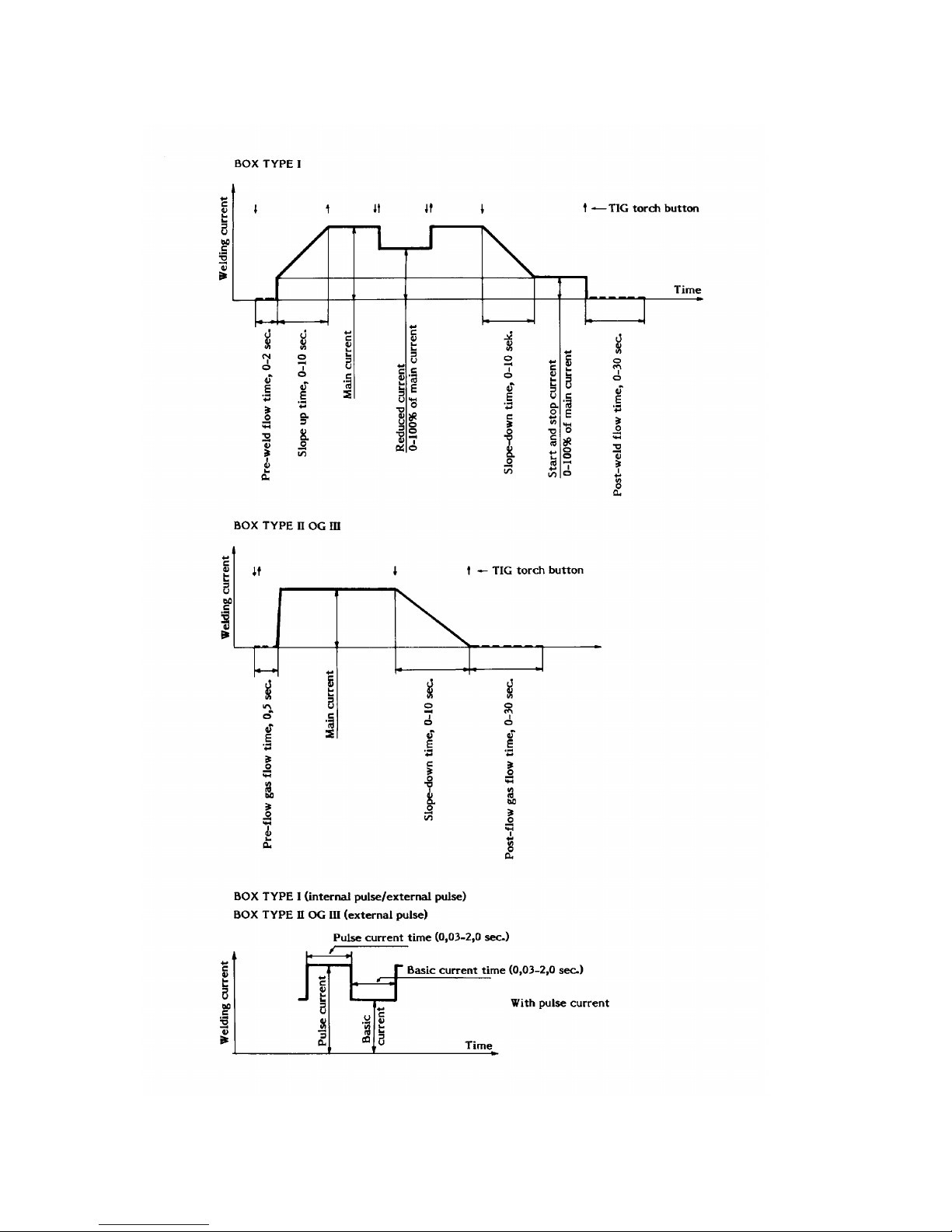
Illustration of control programmes
for box I
............................................................
13
Remote control
.................................................
15
Technical data for connection
of remote control
..............................................
17
Maintenance
.......................................................
18
Functions HF
......................................................
18
Faults
..................................................................
19
Welding tables
....................................................
20
4
Electromagnetic emissions and the radiation of electromagnetic disturbances
This welding equipment for industrial and professional use is in
conformity with the European Standard EN50199. The purpose
of this standard is to prevent the occurrence of situations where
the equipment is disturbed or is itself the source of disturbance
in other electrical equipment or appliances. The arc radiates
disturbances, and therefore, a trouble-free performance without
disturbances or disruption, requires that certain measures are
taken when installing and using the welding equipment. The
user must ensure that the operation of the machine does not
occasion disturbances of the above mentioned nature.
The following shall be taken into account in the surrounding
area:
1. Supply and signalling cables in the welding area which are
connected to other electrical equipment.
2. Radio or television transmitters and receivers.
3. Computers and any electrical control equipment.
4. Critical safety equipment e.g. electrically or electronically
controlled guards or protective systems.
5. Users of pacemakers and hearing aids etc.
6. Equipment used for calibration and measurement
7. The time of day that welding and other activities are to be
carried out.
8. The structure and use of buildings.
If the welding equipment is used in a domestic establishment it
may be necessary to take special and additional precautions in
order to prevent problems of emission (e.g. information of
temporary welding work).
Methods of reducing electromagnetic emissions:
1. Avoid using equipment which is able to be disturbed.
2. Use short welding cables.
3. Place the positive and the negative cables close together.
4. Place the welding cables at or close to floor level.
5. Remove signalling cables in the welding area from the
supply cables.
6. Protect signalling cables in the welding area, e.g. with
selective screening.
7. Use separately-insulated mains supply cables for sensitive
electronic equipment.
8. Screening of the entire welding installation may be considered under special circumstances and for special applications.
WARNING
Arc welding and cutting can be dangerous to the user, people working nearby, and the surroundings if the
equipment is handled or used incorrectly. Therefore, the equipment must only be used under the strict observance
of all relevant safety instructions. In particular, your attention is drawn to the following:
Electricity
- The welding equipment must be installed according to safety regulations and by a properly trained and qualified
person.
- Avoid all contact with live components in the welding circuit and with electrodes and wires if you have bare hands.
Always use dry welding gloves without holes.
- Make sure that you are properly and safely earthed (e.g use shoes with rubber sole).
- Use a safe and stable working position (e.g. avoid any risk of accidents by falling).
- Make sure that the welding equipment is correctly maintained. In the case of damaged cables or insulation work must
be stopped immediately in order to carry out repairs.
- Repairs and maintenance of the equipment must be carried out by a properly trained and qualified person.
Light and heat emissions
- Protect the eyes as even a short-term exposure can cause lasting damage to the eyes. Use a welding helmet with
suitable radiation protection glass.
- Protect the body against the light from the arc as the skin can be damaged by welding radiation. Use protective
clothes, covering all parts of the body.
- The place of work should be screened, if possible, and other persons in the area warned against the light from the arc.
Welding smoke and gases
- The breathing in of the smoke and gases emitted during welding is damaging to health. Make sure that any exhaust
systems are working properly and that there is sufficient ventilation.
Fire hazard
- Radiation and sparks from the arc represent a fire hazard. As a consequence, combustible materials must be removed
from the place of welding.
- Working clothing should also be secure against sparks from the arc (e.g. use a fire-resistant material and watch out for
folds and open pockets).
Noise
- The arc generates surface noise according to welding task. In some cases, use of hearing aids is necessary.
Use of the machine for other purposes than it is designed for (e.g. to unfreeze water pipes) is strongly deprecrated. If
occasion should arise this will be carried out without responsibility on our part.
Read this instruction manual carefully
before the equipment is installed and in operation

5
GENERAL DESCRIPTION
The
MTE
machines are single-phase, thyristor
controlled AC/DC welding machines for manual
electrode welding with all types of electrodes as well
as for manual and automatic TIG welding.
The special construction of the power source with a
bifilar-wound welding inductor provides square
waved welding current when welding AC. Contrary to
a conventional welding machine with sine waves,
square waves have the advantage that the current
tops are reduced to ensure a softer arc and less load
on the electrode when TIG welding. The special
construction of the machine allows an adjustment of
the relation between the positive and the negative
half-wave to obtain the correct relation between
cleaning and penetration, that is, AC balance.
The square wave technique in conjunction with the
balance adjustment ensure a stable arc and a better
penetration as well as a reduced electrode wastage.
The all-electronic control unit ensures that the actual
welding current corresponds to the set value.
When electrode welding an "anti-sticking" device
prevents electrodes "sticking" to the workpiece as
the current is reduced to 5 A in case of short-circuit.
A watercooling unit type CTU 3000 (part no:
76118013) can be mounted.
TECHNICAL DATA
MTE 320 A/W
Duty cycle % X : 100 60 30
Permitted load I2:
190 245 320
At voltage V U2:
28 30 30
MAINS VOLTAGE / CURRENT
U1: 1 x 220 I1:
48 65 88
U1: 1 x 250 I1:
42 57 77
U1: 1 x 380 I1:
28 38 51
U1: 1 x 415 I1:
26 36 48
U1: 1 x 440 I1:
24 33 44
*) U1: 1 x 500 I1:
21 28 39
Consumption kvA :
12,9 16,7 21,8
Consumption max. kvA :
25
Current range AC :
20-320
Current range DC :
5-320
Open circuit voltage AC :
84-90 dc
Open circuit voltage DC :
84-90 dc
Ripple voltage, open cir. :
< 5%
**) Effect 150 A/26 V :
0,52
**) Effect cos.phi. :
0,77
**) Efficiency :
0,60
No load consumption kW :
0,5
1
Protection class :
IP21AF
Standard :
EN60974-1
EN50199
LxWxH, air mm :
1020x570x855
LxWxH, water mm :
1020x570x1010
Weight kg :
224
*)
Not standard, can be delivered for other voltages
**)
AC-balance set at 50%
1
Indicates that the machine cannot be used outside in the rain

6
TECHNICAL DATA
BOX TYPE: I II III
Infinitely variable balance adjustment between positive/negative halfwaves X X X
4 cycle, self hold X X X
2 cycle, latching X X X
Spot welding, infinitely variable 0.5-10 sec. X
Electrode welding AC and DC X X X
Hot-start when electrode welding, infinitely variable from 0-100% X X X
Pre-flow, gas flow, fixed X X
Pre-flow, gas flow, infinitely variable 0-2 sec. X
Post-flow, gas flow, infinitely variable 0-30 sec. X X X
Infinitely variable slope-up, 0-10 sec. X
Infinitely variable slope-down, 0-10 sec. X X X
Infinitely variable reduced current level X
Infinitely variable start and stop current X
Analog ammeter X
Digital ammeter X X
Connection of remote control X X
Pulsatory arc via remote control X X
Pulsatory arc via internal reg. X
Pulse current time: (0.03-2.0 sec.)
Basic current time: (0.03-2.0 sec.)
Pulse frequencies: Max. 33.3 Hz = 1998 P/min.
Min. 0.5 Hz = 30 P/min.

7
INITIAL OPERATING
Mains connection
The mains cable is taken through the sleeve at the
back of the machine and is connected to the
terminal strip at L1 and L2. The yellow/green earth
connection is attached to the marked screw.
Before the machine is connected to the mains
supply, it must be ensured that the welding
transformer is connected to the correct voltage. A
switch diagram for the various voltages is placed at
the terminal strip on the transformer. The terminal
strip is placed behind the left side panel.
Configuration:
MIGATRONIC disclaims all responsibility for
damaged cables and other damages related to
welding with under sized welding torch and welding
cables measured by welding specifications e.g. in
relation to permissible load.
WARNING:
electrical mains power must be switched off before
the cabinet is opened, and only qualified and
authorized electricians should work on electrical
machines.
Connection of welding cables
The welding and return cables are connected to the
sockets on the front of the machine. After
connection the plugs should be turned
approximately 90° to avoid damage being caused
by high contact resistance.
The control box
All control functions are built into the sealed and
easily removed control box.
By loosening the two Allen screws on the front of
the machine the control box can be removed
without opening the machine.
On the back of the control box is both a multiplug
which connects the control box to the machine
modules, and the fuse for the protection of the
remote control circuit.
The control box is available in 3 versions with
different control functions.
WARNING! Only exchange the control box
when the electrical mains power is switched
off.
Fuse sizes and cable sizes for various mains voltages.
Mains voltage 220/250 V 380/415 V 440 V
500 V
Fuse Mains
cable
Fuse Mains
cable
Fuse Mains
cable
Fuse Mains
cable
MTE 320*
63 A 16
?
50 A 10
?
35 A 6
?
35 A 6
?
incl. phase compensating condenser.
8
DEFINITIONS
9
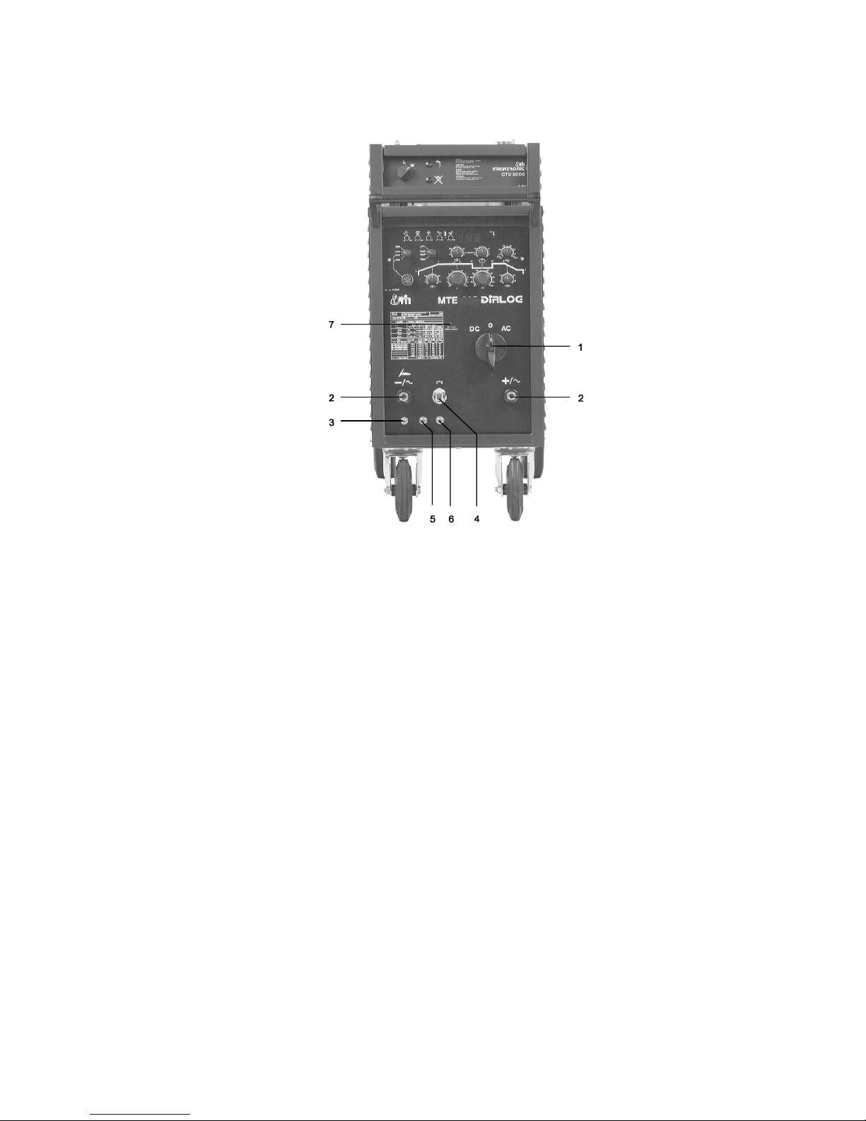
ADJUSTMENT FUNCTIONS
1. Mains switch and switch between AC and
DC.
When the machine is turned on, this is
indicated by light in the ammeter, and a short
opening of the solenoid valve to purge gas
hose.
2. Welding cable sockets.
3. Quick release connection
for shielding gas.
4. Multiplug
for the connection of TIG torch
control wire.
5. Quick release connection
for water flow to
water cooled TIG torch.
6. Quick release connection
for recirculation of
water from water cooled TIG torch.
7. Safety control.
Control lamp is turned on if there is more than
9 V AC on the welding cable sockets. This
lamp should not light when not welding.
The construction of the MTE machines
ensures that the open circuit voltage is
always
a DC voltage
with a ripple voltage less than 5
per cent, also for AC welding.
If the lamp lights when not welding, the
machine does not meet the safety regulations
for welding under special conditions as
described in the power current regulations.
It is usual for the lamp to light during AC
welding.
10
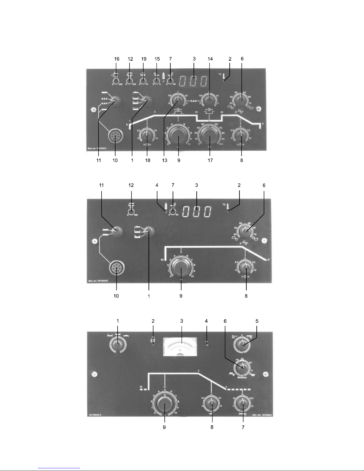
ADJUSTMENT FUNCTIONS BOXES
TYPE I
TYPE II
TYPE III

11
ADJUSTMENT FUNCTIONS BOXES
1. Switch for functions:
Self hold
,
seam
,
electrode welding
. Control boxes of type I are also equipped
with the spot welding function .
If the switch is set at electrode welding the
"hot-start" and "anti-sticking" automatics are
activated. In the other positions these functions
are automatically cut out.
If the machine is activated by a pressure on the
torch button when it is not welding, the machine
is automatically cut out after approximately 10
sec. (self hold and spot welding).
2. Overload indicator
The red lamp lights if the automatic thermal
overload protection device has cut out the
machine. The thermostatically controlled fan
continues working until the machine has cooled
to normal temperature, after which the red light
will turn off automatically and the machine is
ready for use.
3. Ammeter
Shows the set welding current. The machine is
equipped with a very exact electronic circuit
measuring the welding current. On the basis of
the measured and the set current, comparisons
and adjustments are currently made to ensure a
constant welding current irrespectively of
varying mains voltage, cable lengths or machine
heating.
4. Green control lamp
indicating that the solenoid
valve has opened for the shielding gas
5.HF switch
Only on box type III. Boxes of type I and II have
automatic switch.
If the selector switch is at , the HF will work
only at the time of ignition and will cut out
automatically when the arc is stable. At ,
the HF striking works during the whole welding
activity. This position is used for AC welding.
During electrode welding the HF striking is
automatically cut out.
6. AC balance
Button for adjustment of the relation between
cleaning effect and penetration at aluminium
welding. This is done through a regulation of the
positive and negative halfwaves.
A setting at "70" gives the highest penetration
and "45" the highest cleaning effect. At DC welding the AC balance is set at "50" as this gives
the lowest consumption of mains current. At
type I and II boxes, this happens automatically.
7. Post-weld gas flow
The post-weld gas flow time should be set in
accordance with the plate thickness and the
diameter of the tungsten electrode to prevent
oxidation of electrode and welding seam when
the welding is ended. The time is correctly set
when there is no temper colour at the end of the
tungsten electrode after the burn-back delay is
over, and a correct setting will extend the life of
the tungsten electrode. The max. post-weld gas
flow time is 30 sec.
8 Slope down control
Crater formation at the end of a weld seam can
be prevented by using this control to set the time
for the welding current to decay after completing
the welding seam. If the switch (pos. 1) is at self
hold , the slope down works as long as the
torch button is held down and the welding ends
when it is released. If the switch is at seam
or spot . the welding only stops when
the slope down time has expired.
9. Set current
The welding current is adjusted by this
potentiometer equipped with a multidrive
reduction.
Control boxes I and II are furthermore equipped
with the following:
10. Multiplug
for connection of remote control or
welding robot. Signals for set current, measured
current and "arc established".
11. Remote control switch
Switch between external or internal current
adjustment and for box I furthermore internal
adjustment of pulsatory arc. Machines equipped
with box I or II can also weld with pulsatory arc
by addition of remote control FPB (part no.
76116383). Max. pulse frequency is 16 Hz.
12. Hot start
This control can only be used when electrode
welding.
If this control is set at 100% the machine will
start with a welding current twice as high as the
set main current (pos. 9). This hot-start surge
continues for 1 second after which the machine
automatically drops to the set welding current.
 Loading...