

Migatronic FLEX2 3000 Compact Instruction Manual
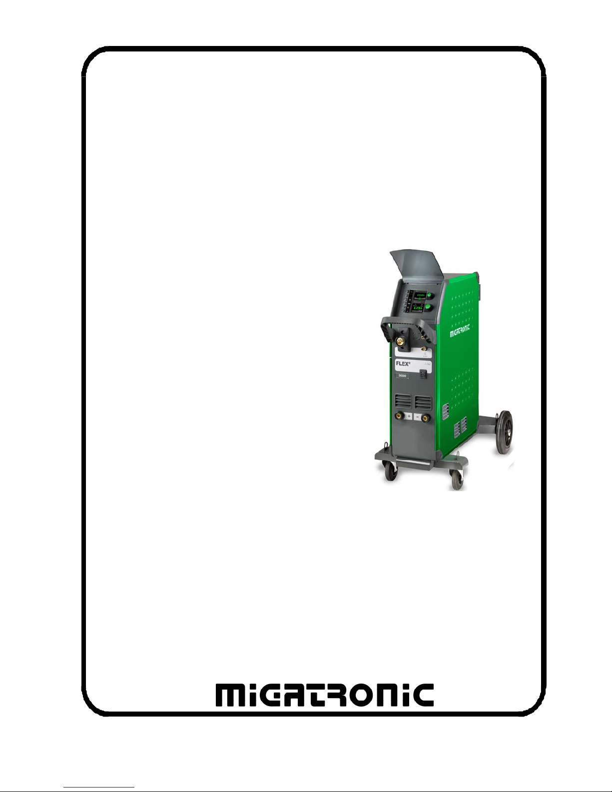
FLEX2 3000 Compact
Brugsanvisning
Instruction manual
Betriebsanleitung
Manuel d’instruction
Bruksanvisning
Käyttöohje
Gebruikershandleiding
Manuale d’istruzione
Manual de instrucciones
Instrukcja obsługi
Kezelési útmutató
Valid from 2016 week 33 50113761 H
2
EC DECLARATION OF CONFORMITY
MIGATRONIC A/S
Aggersundvej 33
9690 Fjerritslev
Denmark
hereby declare that our machine as stated below
Type: FLEX
2
3000 C
As of Week 02 2013
conforms to directives 2014/35/EU
2014/30/EU
2011/65/EU
European Standards: EN/IEC60974-1
EN/IEC60974-2
EN/IEC60974-5
EN/IEC60974-10 (Class A)
Issued in Fjerritslev 20.04.2016
Mads Prebensen
CEO
DANSK ................................................................................ 3
ENGLISH .......................................................................... 17
DEUTSCH .......................................................................... 31
FRANÇAIS ........................................................................ 45
SVENSKA .......................................................................... 59
SUOMI ............................................................................... 73
NEDERLANDS ................................................................. 87
ITALIANO ....................................................................... 101
ESPAÑOL ...................................................................... 115
POLSKI ............................................................................ 129
MAGYAR ......................................................................... 143

3
DANSK
INDHOLDSFORTEGNELSE
Advarsel / Elektromagnetisk støjudstråling .......................... 4
Produktprogram ................................................................... 5
Tilslutning og Ibrugtagning ..............................................6 - 7
Tekniske data ....................................................................... 8
Software ............................................................................... 9
Specielle funktioner .................................................... 10 - 11
Fejlhåndtering .................................................................... 13
Vedligeholdelse .................................................................. 13
Fejlkoder ..................................................................... 14 - 15
Garantibestemmelser ......................................................... 15
Svejsetabel ....................................................................... 157
Sliddele – trådfremføring .................................................. 158
4
Elektromagnetisk støjudstråling
Dette svejseudstyr, beregnet for professionel anvendelse,
overholder kravene i den europæiske standard
EN/IEC60974-10 (Class A). Standarden har til formål at sikre, at
svejseudstyr ikke forstyrrer eller bliver forstyrret af andet elektrisk
udstyr som følge af elektromagnetisk støjudstråling. Da også
lysbuen udsender støj, forudsætter anvendelse uden forstyrrelser, at
der tages forholdsregler ved installation og anvendelse. Brugeren
skal sikre, at andet elektrisk udstyr i området ikke forstyrres.
Følgende skal tages i betragtning i det omgivne område:
1. Netkabler og signalkabler i svejseområdet, som er tilsluttet
andre elektriske apparater.
2. Radio- og fjernsynssendere og modtagere.
3. Computere og elektroniske styresystemer.
4. Sikkerhedskritisk udstyr, f.eks. overvågning og processtyring.
5. Brugere af pacemakere og høreapparater.
6. Udstyr som anvendes til kalibrering og måling.
7. Tidspunkt på dagen hvor svejsning og andre aktiviteter,
afhængig af elektrisk udstyr, foregår.
8. Bygningers struktur og anvendelse.
Hvis svejseudstyret anvendes i boligområder kan det være
nødvendigt at tage særlige forholdsregler (f.eks. information om
midlertidigt svejsearbejde).
Metoder til minimering af forstyrrelser:
1. Undgå anvendelse af udstyr, som kan blive forstyrret.
2. Anvend korte svejsekabler.
3. Læg plus- og minuskabel tæt på hinanden.
4. Placer svejsekablerne på gulvniveau.
5. Fjern signalkabler i svejseområdet fra netkabler.
6. Beskyt signalkabler i svejseområdet f.eks med skærmning.
7. Benyt isoleret netforsyning til følsomme apparater.
8. Overvej skærmning af den komplette svejseinstallation.
ADVARSEL
Lysbuesvejsning og -skæring kan ved forkert brug være farligt for såvel bruger som omgivelser. Derfor må
udstyret kun anvendes under iagttagelse af relevante sikkerhedsforskrifter. Især skal man være opmærksom
på følgende:
Elektrisk stød
- Svejseudstyret skal installeres forskriftsmæssigt. Maskinen skal jordforbindes via netkablet.
- Sørg for regelmæssig kontrol af maskinens sikkerhedstilstand.
- Beskadiges kabler og isoleringer, skal arbejdet omgående afbrydes og reparation foretages.
- Kontrol, reparation og vedligeholdelse af udstyret skal foretages af en person med den fornødne faglige indsigt.
- Undgå berøring af spændingsførende dele i svejsekredsen eller elektroder med bare hænder. Brug aldrig defekte
eller fugtige svejsehandsker.
- Isolér Dem selv fra jorden og svejseemnet (brug f.eks fodtøj med gummisål).
- Brug en sikker arbejdsstilling (undgå f.eks. fare for fald).
- Følg reglerne for "Svejsning under særlige arbejdsforhold" (Arbejdstilsynet).
Svejse- og skærelys
- Beskyt øjnene, idet selv en kortvarig påvirkning kan give varige skader på synet. Brug svejsehjelm med foreskrevet
filtertæthed.
- Beskyt kroppen mod lyset fra lysbuen, idet huden kan tage skade af stråling. Brug beskyttende beklædning, der
dækker alle dele af kroppen.
- Arbejdsstedet bør om muligt afskærmes, og andre personer i området advares mod lyset fra lysbuen.
Svejserøg og gas
- Røg og gasser, som dannes ved svejsning, er farlige at indånde. Sørg for passende udsugning og ventilation.
Brandfare
- Stråling og gnister fra lysbuen kan forårsage brand. Letantændelige genstande fjernes fra svejsepladsen.
- Arbejdstøjet skal være sikret mod gnister og sprøjt fra lysbuen. Brug evt. brandsikkert forklæde og pas på
åbenstående lommer.
- Særlige regler er gældende for rum med brand- og eksplosionsfare. Følg disse forskrifter.
Støj
- Lysbuen frembringer akustisk støj, og støjniveauet er betinget af svejseopgaven. Det vil i visse tilfælde være
nødvendigt at beskytte sig med høreværn.
Farlige områder
- Stik ikke fingrene ind i de roterende tandhjul i trådfremføringsenheden.
- Særlig forsigtighed skal udvises når svejsearbejdet foregår i lukkede rum eller i højder hvor der er fare for at falde
ned.
Placering af svejsemaskinen
- Placer svejsemaskinen således, at der ikke er risiko for, at den vælter.
- Særlige regler er gældende for rum med brand- og eksplosionsfare. Følg disse forskrifter.
Anvendelse af maskinen til andre formål end det, den er beregnet til (f.eks. optøning af vandrør) frarådes og sker i givet
tilfælde på eget ansvar.
Gennemlæs denne betjeningsvejledning omhyggeligt,
inden udstyret installeres og tages i brug!

5
PRODUKTPROGRAM
FLEX
2
3000 Compact:
300A svejsemaskine til MMA og MIG/MAG svejsning.
Maskinen er luftkølet og leveres med integreret vogn
og indbygget trådfremføring med 4-hjuls trissetræk.
Svejseslanger og kabler
Til maskinerne kan MIGATRONIC fra sit
produktprogram levere elektrodeholdere, MIG/MAGslanger, returstrømkabler, mellemkabler, sliddele mm.
Brænderkøling (ekstraudstyr)
Et integreret kølemodul kan bestilles ved ordreafgivelse af maskinen, således at både vandkølede og
gaskølede brændere kan benyttes.
Push-pull (ekstraudstyr)
FLEX
2
3000 Compact kan eftermonteres med
ekstraudstyr, således at en MIGATRONIC Push-Pullbrænder kan tilsluttes og anvendes.
Vogn med omkoblingsmodul (ekstraudstyr)
En vogn med indbygget omkoblingsmodul der
automatisk tilpasser til den aktuelle trefasede
netspænding (230-500V) til FLEX
2
3000 Compact.
Intelligent Gas Control (ekstraudstyr)
Gassparekit, der automatisk regulerer gasmængden.
Tilbehørsprogram
Kontakt nærmeste forhandler for oplysninger om
FLEX
2
3000 Compact tilbehørsprogram.
6
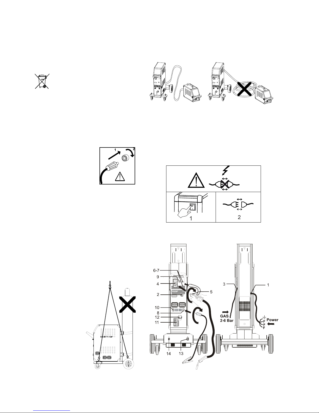
TILSLUTNING OG IBRUGTAGNING
Installation
I det følgende beskrives, hvorledes de enkelte
dele af maskinen kobles sammen, sluttes til
forsyningsnettet og tilsluttes gasforsyningen mm.
Tallene i parentes henviser til figurerne i afsnittet.
Bortskaf produktet i overensstemmelse
med gældende regler og forskrifter.
www.migatronic.com/goto/weee
Konfigurering
Hvis maskinen udstyres med svejsebrænder og
svejsekabler, der er underdimensioneret i forhold
til svejsemaskinens specifikationer f.eks. med
hensyn til den tilladelige belastning, påtager
MIGATRONIC sig intet ansvar for beskadigelse
af kabler, slanger og eventuelle følgeskader.
Vigtigt!
Når stelkabel og svejsebrænder tilsluttes maskinen,
er god elektrisk kontakt
nødvendig, for at undgå at
stik og kabler ødelægges.
Generatordrift
Denne svejsemaskine kan anvendes på alle
forsyninger, som afgiver sinusformet strøm og
spænding, og som ikke overskrider de tilladte
spændingstolerancer, der er angivet i de
tekniske data.
Motoriserede generatorer, som overholder
ovenstående, kan anvendes som forsyning.
Spørg altid generatorleverandøren til råds før
du tilslutter din svejsemaskine.
MIGATRONIC anbefaler at anvende en
generator, der har elektronisk regulator og som
kan levere mindst 1,5 x svejsemaskinens
maksimale kVA forbrug.
Garantien bortfalder ved skader, som er opstået
på grund af forkert eller dårlig forsyning.
Løfteanvisning
Når maskinen skal
løftes, skal løftepunkterne, som vises
på figuren, anvendes.
Maskinen må ikke
løftes med monteret
gasflaske!
Det er vigtigt at svejseslange, stelkabel og eventuelt
mellemkabel ligger udstrakt som vist på figuren, da det
ellers vil påvirke svejseperformance og i værste fald kan
ødelægge svejsemaskinen.
Nettilslutning
Inden maskinen tilkobles forsyningsnettet, skal det
kontrolleres, at den er beregnet til den aktuelle
netspænding, og at forsikringen i forsyningsnettet er i
overensstemmelse med typeskiltet. Netkablet (1) skal
tilsluttes 3-faset vekselstrøm 50 eller 60 Hz og
beskyttelsesjord. Rækkefølgen af faserne er uden
betydning. Maskinen tændes med hovedafbryderen (2).
7
Tilslutning af beskyttelsesgas
Gasslangen, som udgår fra bagsiden af maskinen (3),
tilsluttes en gasforsyning med en trykreduktion til 2-6
bar. En/to gasflasker kan fikseres bag på vognen.
Tilslutning af brænder for MIG/MAG-svejsning
Svejseslangen trykkes i ZA-koblingen (4), og spændeomløberen (5) på enden af slangen spændes med
hånden. Hvis brænderen er vandkølet, tilsluttes endvidere de to slanger: RØD og BLÅ til lynkoblinger (6 -
7). Stelkablet tilsluttes svejseminus (8).
Hvis brænderen er en MIG Manager
®
, skal der endvidere tilsluttes et multistik til fronten af maskinen (9).
NB: MIG Manager
®
kan kun tilsluttes hvis der er mon-
teret tilslutningskit i maskinen (ekstra udstyr).
Tilslutning af elektrodeholder for MMA
Elektrodeholder og returstrømkabel tilsluttes plusudtag
(10) og minusudtag (8). Polariteten vælges efter
elektrodeleverandørens anvisning.
Kontrol af kølevæske
Hvis maskinen er leveret med integreret kølemodul,
bør kølevandstanden med jævne mellemrum
inspiceres ved hjælp af vandstandskontrollen (11).
Efterfyldning af kølevæske sker gennem påfyldningsstudsen (12).
Justering af trådbremse
Trådbremsen skal sikre, at trådspolen bremses
tilstrækkelig hurtigt, når svejsningen ophører. Den
nødvendige bremsekraft er afhængig af vægten på
trådrullen, og den maksimale trådhastighed der
anvendes. Et bremsemoment på 1,5-2,0 Nm vil være
fyldestgørende til de fleste anvendelser.
Justering:
- Afmonter drejeknappen ved at
stikke en tynd skruetrækker
ind bagved knappen og ryk
derefter knappen ud.
- Juster trådbremsen ved at
spænde eller løsne låsemøtrikken på trådnavets aksel
- Monter knappen igen ved at
trykke den på plads i rillen.
Vogn med automatisk netspændingsomkobling
(ekstra udstyr)
Maskiner leveret med autotrafo monteret i vognen kan
tilsluttes følgende spændinger:
3*230V, 3*400V, 3*440V og 3*500V.
Autotrafoen tændes (grøn indikator lyser) på
netafbryderen (13). Den indbyggede energisparefunktion vil automatisk slukke for svejsemaskinen efter
40 minutters stilstand. Tryk på knappen (14) for at
tænde maskinen igen (rød indikator lyser).
Energisparefunktionen kan sættes ud af drift af en
Migatronic tekniker.
Tænd Tryk Svejs
Nu er maskinen næsten klar til brug.
Tænd svejsemaskinen
På hovedafbryderen (2)
Vælg intern/ekstern kontrol (Se side 10)
Vælg svejseprogram
Der skal vælges et svejseprogram, som passer til
den svejsetråd og beskyttelsesgas eller evt.
elektrode, der skal svejses med.
Se i Quickguide hvordan det vælges for din
svejsemaskine.
Indstil svejsestrøm
Se Quickguide
Svejs
8
TEKNISKE DATA
STRØMKILDE FLEX2 3000C
Netspænding ±15% (50-60Hz) 3x400 V
Sikring 16 A
Netstrøm, effektiv 16,5 A
Netstrøm, max. 19,0 A (380V) / 18,1 A (400V)
Effekt, 100% 10,9 kVA
Effekt, max. 12,5 kVA
Tomgangsforbrug 40 VA
Virkningsgrad 0,85
Effektfaktor 0,90
Strømområde 15-300 A
Intermittens 20°C (MIG) 300A/100%
Intermittens 40°C (MIG) 270A/100%
Intermittens 40°C (MIG) 300A/80%
Tomgangsspænding 69 – 76 V
1
Anvendelsesklasse
S
2
Beskyttelsesklasse IP 23
Normer
EN/IEC60974-1
EN/IEC60974-2
EN/IEC60974-5
EN/IEC60974-10 (Class A)
Dimensioner (HxBxL) luftkølet/vandkølet 90,6x52,4x92,5 cm/105,1x52,4x92,5 cm
Vægt luftkølet/vandkølet 58 kg/69 kg
TRÅDFREMFØRING INTERN KØLEMODUL
Trådfremføringshastighed 0,5-30 m/min Køleeffekt (v/1,0 l. flow) 1100 W (1,0 l/min)
Brændertilslutning EURO centraltilslutning Tankkapacitet 3,5 liter
Trådspolediameter 300 mm Flow 1,2 bar – 60°C 1,75 l/min
Intermittens 40°C 420A/100% Tryk max. 3 bar
Intermittens 40°C 500A/60% Normer EN/IEC60974-2
2
Beskyttelsesklasse IP 23
Tråddiameter 0,6-2,4 mm
Gastryk max. 0,5 MPa (5,0 bar)
Normer EN/IEC60974-5
EN/IEC60974-10 (Class A)
BETJENING PROCES VÆRDIOMRÅDE
Valg af tastemetode MIG/MAG 2-takt / 4-takt
Kontrol af strøm/spænding/trådhastighed - lokal / brænderkontrol/fjernkontrol
Rangering af tråd MIG/MAG Ja
Brænderkøling - vandkølet / gaskølet
Hotstart % MMA 0,0% – 100,0%
Hotstart-tid MMA 0,0 – 20,0 s
Arc power MMA 0,0 – 150,0%
Gasforstrømning MIG/MAG 0,0 – 10,0 s
Krybestart MIG/MAG 0,5 – 24,0 m/min
Hotstart Synergisk -99% – +99%
Hotstart tid Synergisk 0,0 – 20,0 s
Strømsænkningstid Synergisk 0,0 – 10,0 s
Stopstrøm Synergisk 0 – 100%
Stopstrømtid Synergisk 0,0-10,0 s
Burn back MIG/MAG 0 – 30
Gasefterstrømning MIG/MAG 0,0 – 20,0 s
Sekvenstimer / punktsvejsetid MIG/MAG 0,0 – 50,0 s
DUO PlusTM effekttrim MIG/MAG 0 – 50%
DUO Plus
TM
tid MIG/MAG 0,1 – 9,9 s
Elektronisk drossel -5,0 – +5,0
Sekvens 9 sekvenstrin
1
S
Maskiner opfylder de krav der stilles under anvendelse i områder med forøget risiko for elektrisk chok
2
Angiver at maskinen er beregnet for såvel indendørs som udendørs anvendelse
9
SOFTWARE
Hvis kontrolboksen udskiftes er det nødvendigt at
lægge software ind i den nye boks igen, ved hjælp af
et SD kort.
Nyeste software kan downloades under
Product software på www.migatronic.com/login.
Softwaren skal gemmes på et SD kort, som skal
indeholde mapperne og én eller flere af filerne som
vist herunder.
SD-kort kan bestilles på varenummer 12646000.
Software indlæsning
Indsæt FLEX
2
3000 Compact SD-kortet i slidsen i
maskinens højre side.
Tænd maskinen.
Displayet blinker kortvarigt med seks streger.
Vent indtil maskinens display viser den indstillede
strøm.
Sluk maskinen og tag SD-kortet ud
Maskinen er nu klar til brug.
Hvis SD-kortet indeholder software til andre enheder
f.eks.:
10020115.cry RWF
10020113.cry RCI
vil disse enheder blive opdateret, hvis de er koblet til
CAN netværket.
Bemærk at det kan tage længere tid at foretage
opdateringer, vent derfor venligst med at slukke
maskinen, indtil der vises driftsbillede på
FLEX
2
3000 Compact.
Licens SW
Ved tilkøb af ekstralicenser til programmer eller
særlige funktioner skal MigaLic.dat filerne indlæses på
samme vis som SW-pakker. Husk at gemme en
sikkerhedskopi af filerne.
MigaLic.txt filen indeholder information om maskinens
licensnummer og de gemte licenser på SD-kort.
Alle maskinens brugerindstillinger slettes når
filen 10645900.bin indlæses. Tag derfor altid SDkortet ud af maskinen efter opdateringen, for at
undgå at softwaren indlæses hver gang
maskinen tændes.
10
SPECIELLE FUNKTIONER
Konfiguration af intern/ekstern kontrol
Det er muligt at konfigurere intern og ekstern kontrol
ved at trykke på følgende knap i Machine Setupmenuen:
Drej på nederste drejeknap indtil den ønskede
konfiguration vises. Tryk på -tasten for at bekræfte
valget (valgt konfiguration indikeres ved ):
Dialog brænder:
Strøm indstilles både på panelet og fra reguleringsknappen på brænderen.
Spændingstrim indstilles fra panelet.
Sekvens brænder:
Ved valg af enten 3 eller 7 sekvensbrænder defineres
automatisk 3 eller 7 sekvenser, som kun kan skiftes
fra brænderen. Alle andre indstillinger foretages på
panelet.
VIGTIGT!
Såfremt det ikke er muligt at skifte mellem sekvensnumrene 1 til 7 (1 til 3 på ERGO model XMA), skyldes
det forkert valg af sekvensbrænder. Vælg en fra listen
der passer på den aktuelle sekvenstype.
Fjernbetjening:
Strøm indstilles både fra panelet og fra reguleringsknappen på fjernbetjeningen.
Spændingstrim kan kun indstilles fra fjernbetjeningen.
MIG Manager
®
:
Se quick guide for MIG Manager
®
Til-/frakobling af vandkøling (MIG/MAG)
Vandkølefunktionen, skal sikre at den vandkølede
brænder ikke ødelægges. Vandkølingen starter
automatisk, når svejsningen påbegyndes, og stopper
automatisk 3 minutter efter svejsningen er ophørt.
Vandkøling aktiveres ved at trykke på følgende knap:
Når MIG Manager
®
er tilsluttet, kontrollerer den
automatisk vandkølefunktionen og sætter denne
konfiguration ud af drift.
Indstilling af tid
Det er muligt at indstille tiden ved at trykke på
følgende knap i Machine Setup-menuen:
Det er vigtigt at indstille den korrekte tid, hvis der
ønskes logning af f.eks. fejl. Når indstillingen er
foretaget, bekræftes ved at trykke på følgende knap:
11
Låsefunktion (Option)
Det er muligt at indstille det ønskede låseniveau ved
at trykke på følgende knap i Machine Setup-menuen:
Funktioner låses til det valgte låseniveau ved
indsætning af SD-låsekortet og låses op ved at
genindsætte SD-låsekortet.
Genkald af fabriksindstillinger
Dette er en total reset til fabriksindstillinger:
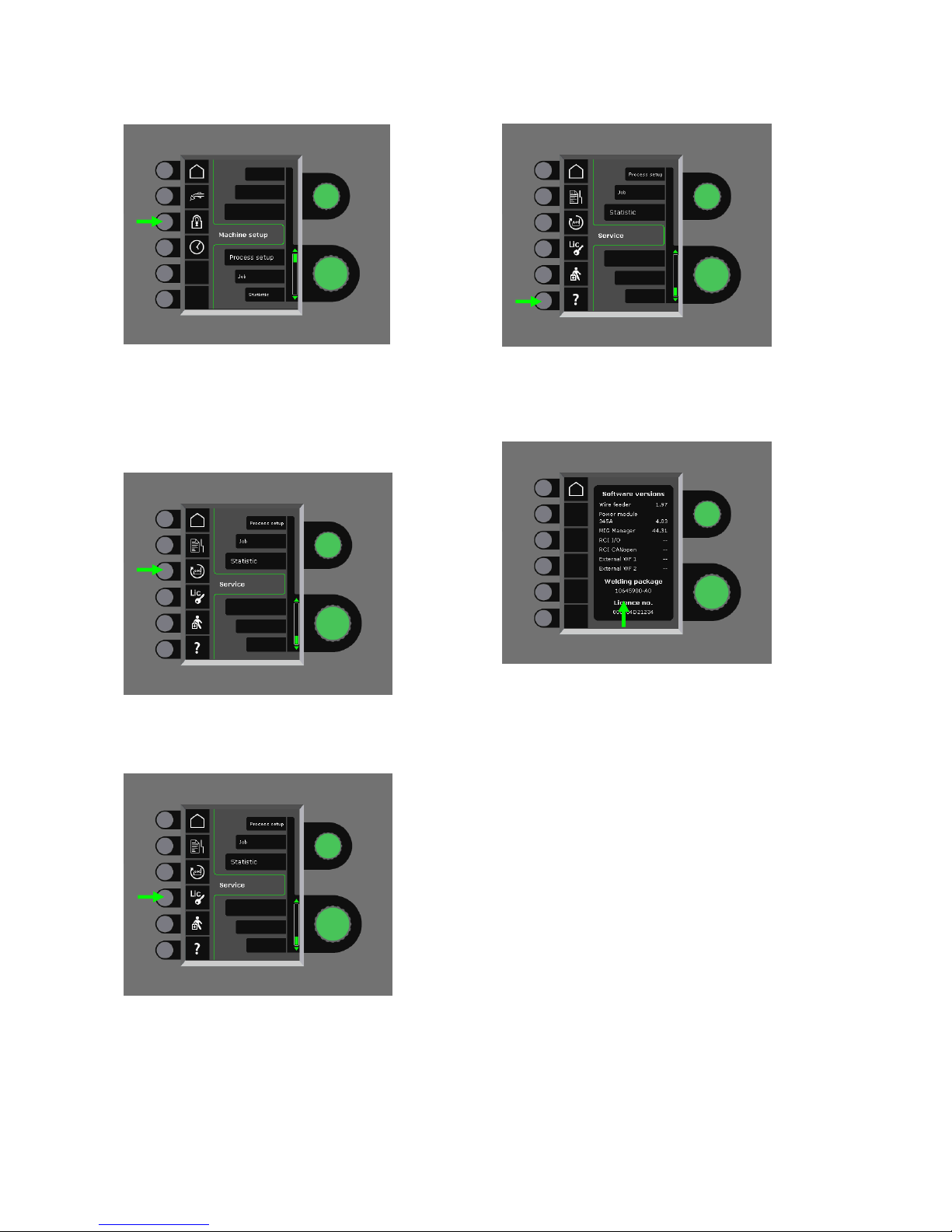
Visning af licensoversigt
Det er muligt at få vist samlet oversigt over antal
licenser:
Visning af softwareversioner/licensnr.
Det er muligt at få vist softwareversioner/licensnr. ved
at trykke på følgende knap i service-menuen:
Licensnr. skal anvendes ved køb af ekstra licenser.
Det er vigtigt at oplyse det korrekte nummer ved
ordreafgivelse og skelne imellem tal, store og små
bogstaver.
12
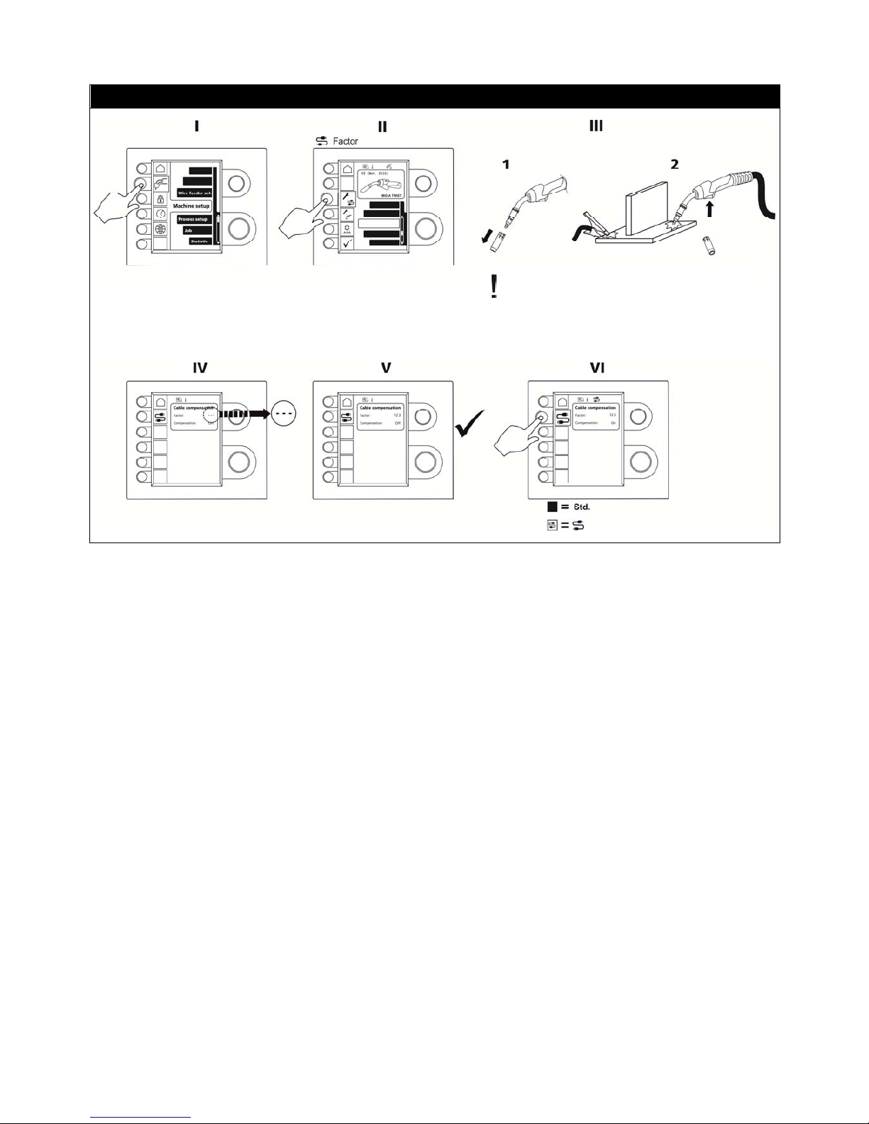
Kabelkompensering (kalibrering af modstand i svejseslange)
Svejseemnets overflade skal være ren for at
sikre god kontakt med brænderen.
13
FEJLHÅNDTERING
FLEX
2
3000 Compact har et avanceret
selvbeskyttelsessystem indbygget. Ved fejl lukker
maskinen automatisk for gastilførslen, afbryder svejsestrømmen og stopper trådfremførelsen.
Udvalgte fejl:
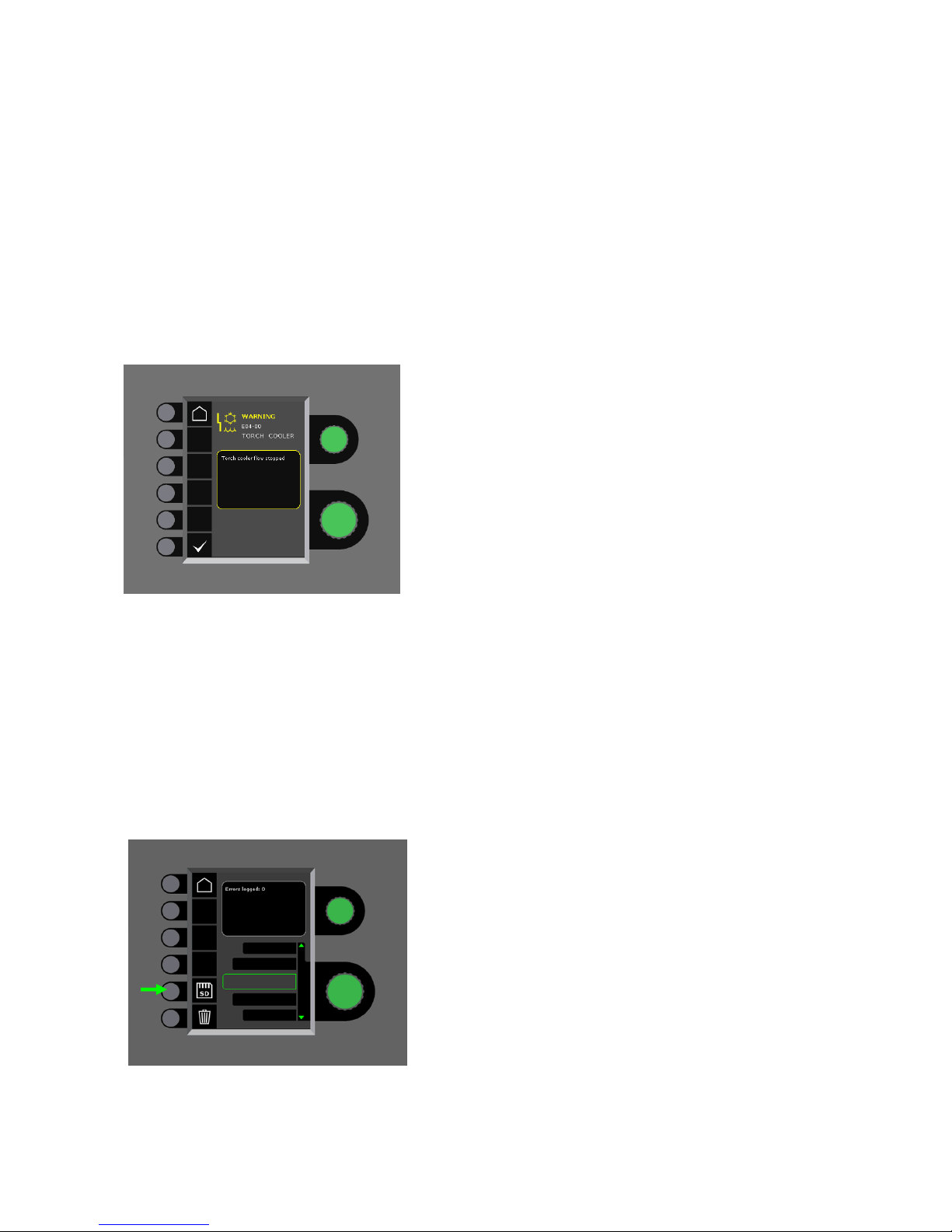
Kølefejl
Kølefejl vises på maskiner med monteret vandflowkit, i
tilfælde af at kølevandet ikke kan cirkulere som følge af
forkert tilslutning eller tilstopning.
Kontroller at køleslangerne er korrekt tilsluttet, efterfyld
vandbeholderen og efterse svejseslange og tilslutningsstudser. Kølefejlen afmeldes med et kort tryk på -
knappen.
Gasfejl
Gasfejl kan skyldes for lavt eller for højt tryk på
gastilførslen.
Kontroller at trykket på gastilførslen er højere end 2 bar
og mindre end 6 bar, svarende til 5 l/min og 27 l/min.
Gasfejl kan sættes ud af funktion ved at indstille manuel
gasflow til 27 l/min. Gasfejlen afmeldes med et kort tryk
på -knappen.
Fejllog
Alle fejl gemmes i maskinens fejllog under menuen
Service. Fejlloggen kan distribueres, når der indsættes
et SD-kort og trykkes på følgende tast:
Fejlloggen er nu gemt på SD-kortet.
Fejlloggen kan nulstilles, når der trykkes på tasten ud
for skraldespanden.
VEDLIGEHOLDELSE
Maskinen skal regelmæssigt vedligeholdes og
rengøres for at undgå funktionsfejl og sikre driftssikkerhed.
Manglende vedligeholdelse har indflydelse på driftssikkerheden og resulterer i bortfald af garanti.
ADVARSEL!
Service- og rengøringsarbejder på åbnede
svejsemaskiner må kun udføres af kvalificeret
personale. Anlægget skal frakobles
forsyningsnettet (netstik trækkes ud!). Vent ca.
5 minutter før vedligeholdelse og reparation, da
alle kondensatorer skal aflades da der er risiko
for stød.
Trådrum
- Rengør trådrummet med trykluft og efterse tråd-
trissernes spor og tænder for slitage, efter behov.
Kølemodul
- Kølevæskeniveau og frostsikring efterprøves, og
kølevæske efterfyldes efter behov.
- Èn gang om året renses vandtank og
vandslangerne i svejseslangen for snavs og
gennemskylles med rent vand. Derefter påfyldes
ny kølevæske. Maskinen leveres fra Migatronic
med kølevæske af typen propan-2-ol i blandingsforholdet 23% propan-2-ol og
77% demineraliseret vand, hvilket giver
frostsikring til –9°C (se bestillingsnummer i
reservedelslisten).
Strømkilde
- Strømkildens ventilatorvinge og køletunnel skal
rengøres med trykluft efter behov.
- Der skal mindst én gang årligt gennemføres
eftersyn og rengøring af kvalificeret
servicetekniker
.
14
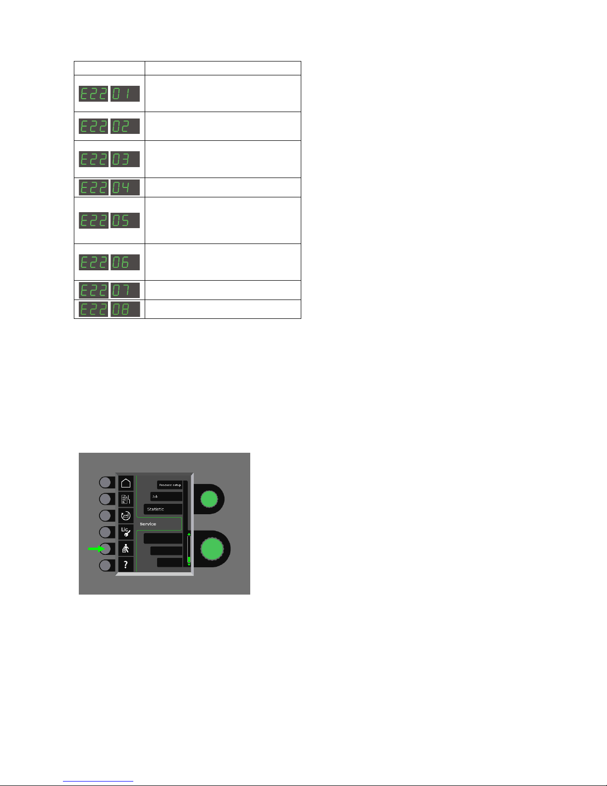
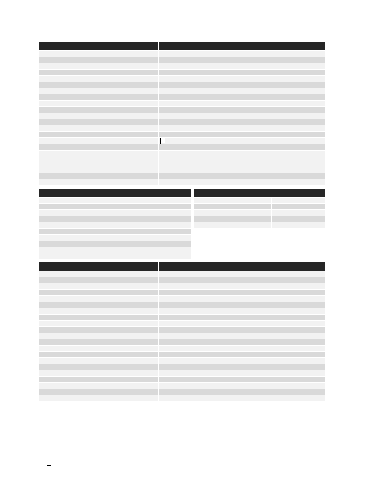
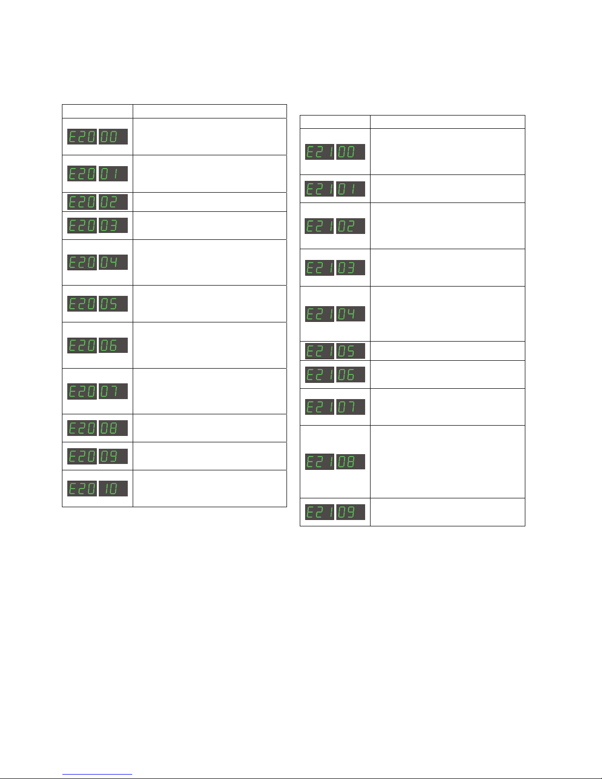
FEJLKODER
Hvis der opstår en fejl under software indlæsning vil en af nedenstående fejlkoder blinke i displayet.
Fejlkoder til MWF software 10001341.cry
Fejlkode Årsag og udbedring
Der er ingen software i kontrolboksen.
Sæt et SD kort med software i boksen
og tænd maskinen.
SD kortet er ikke formateret.
Formater SD kortet i en PC, som FAT
og læg filerne ned på kortet. Eller
anvend et andet SD kort.
SD kortet indeholder ingen software.
Se side 9.
SD kortet har flere filer med samme
navn.
Se side 9.
Kontrolboksen har forsøgt at indlæse
flere data end den kan have i
hukommelsen.
1. Indlæs SD kortet igen.
2. Udskift SD kortet.
3. Tilkald MIGATRONIC Service.
Software på SD kortet er låst til en
anden type kontrolboks.
Anvend et SD kort med software som
passer til din type kontrolboks.
Software på SD kortet er låst til en
anden kontrolboks med et andet
serienummer/stregkode.
Anvend et SD kort med software som
passer til din kontrolboks.
Den interne kopibeskyttelse tillader
ikke adgang til mikroprocessoren.
1. Indlæs SD kortet i maskinen igen.
2. Tilkald MIGATRONIC Service.
Kontrolboksens hukommelses-kreds er
defekt.
Tilkald MIGATRONIC Service.
Kontrolboksens hukommelseskreds er
defekt.
Tilkald MIGATRONIC Service.
Den indlæste fil 10001341.cry er
fejlbehæftet.
1. Indlæs SD kortet igen
2. Udskift SD kortet.
Fejlkoder til Svejseprogrampakke 10645900.bin
Fejlkode Årsag og udbedring
Der er ingen svejseprogrammer i
kontrolboksen.
Sæt et SD kort med software i boksen
og tænd maskinen. Se side 9.
SD kortet er ikke formateret.
Formater SD kortet i en PC, som FAT.
Eller anvend et andet SD kort.
Det er kun muligt at have én fil med
svejseprogrammer.
Sørg for at der kun ligger én fil med
nummeret 10645900.bin på SD
kortet. Se side 9.
Den svejseprogrampakke du forsøger
at indlæse passer ikke til denne
kontrolboks.
Anvend et SD kort med software som
passer til din kontrolboks.
Den svejseprogrampakke du forsøger
at indlæse, er låst til en kontrolboks
med et andet serienummer/stregkode.
Din softwarepakke er kopibeskyttet og
forsøges anvendt på en kontrolboks
der ikke er købt licens til.
Kontrolboksen er defekt.
Tilkald MIGATRONIC Service.
Filen 10645900.bin mangler på SD
kortet.
Se side 9.
Den indlæste file 10645900.bin er
fejlbehæftet.
1. Indlæs SD kortet igen.
2. Udskift SD kortet.
Sigma mappen med filerne findes ikke
på kortet eller er placeret det forkerte
sted.
1. Opret mapperne
MIGA_SW / SIGMA og placér filerne
heri.
2. Udskift SD kortet.
For lidt intern hukommelse
Svejseprogrampakke kan ikke
indlæses
15
Fejlkoder til Power control pakke 10001703.cry
Fejlkode Årsag og udbedring
Den indlæste fil 10001703.cryer
fejlbehæftet.
1. Indlæs SD kortet igen
2. Udskift SD kortet.
SD kortet er ikke formateret.
Formater SD kortet i en PC, som FAT.
Eller anvend et andet SD kort.
Den SW du forsøger at indlæse passer
ikke til denne kontrolboks.
Anvend et SD kort med software som
passer til din kontrolboks.
DSP-printet er defekt.
Tilkald MIGATRONIC Service
Dataoverførselsfejl
Sluk og tænd maskinen igen. Hvis
fejlen kommer endnu en gang
udskiftes SD kortet. Kontakt evt.
forhandleren
Den indlæste fil 10001703.cryer
fejlbehæftet.
1. Indlæs SD kortet igen
2. Udskift SD kortet.
DSP-printet er defekt.
Tilkald MIGATRONIC Service
SD-kortet har for mange filer
indeholdende 10001703.cry-data
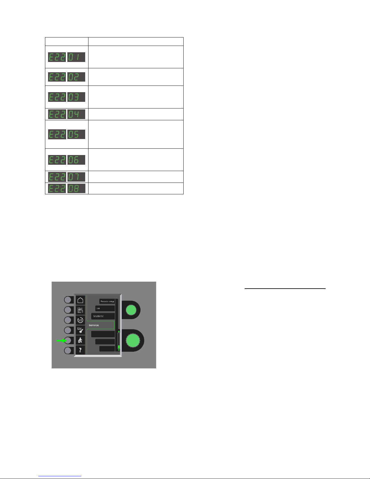
SERVICE
Test
Test funktioner som kun anvendes af serviceteknikeren i forbindelse med servicering af maskinen.
Følgende test kan foretages.:
- Tænd kølemodul
- Tænd blæser
- Tænd magnetventil
- Tænd trådmotor
Følgende information kan aflæses:
- Strømkildetemperatur
- DC link spænding
- IAC modul installeret
GARANTIBESTEMMELSER
Migatronic udfører løbende kvalitetskontrol gennem
hele produktionsforløbet samt afprøvning af de
komplette enheder gennem omfattende test.
Migatronic yder garanti i henhold til nedenstående
bestemmelser ved at udbedre fejl og mangler ved
enheder, der påviseligt og indenfor garantiperioden
måtte skyldes materiale- eller produktionsfejl.
Garantiperioden er 24 måneder for nye
svejsemaskiner, 12 måneder for nyt tilbehør og
6 måneder for reservedele. Garantiperioden regnes
fra dato for fakturering til slutbruger fra Migatronic eller
Migatronics forhandler. I tilfælde af salg gennem
Migatronics forhandler, udløber garantiperioden under
alle omstændigheder senest 36 måneder for nye
svejsemaskiner og 30 måneder for reservedele,
regnet fra dato for fakturering fra Migatronic til
forhandler. Denne frist forlænger på ingen måde
ovennævnte garantiperiode. Den originale faktura
udgør dokumentation for garantiperioden.
Svejseslanger anses som sliddele; og alene fejl og
mangler, der konstateres indenfor 6 uger efter levering
og som skyldes materiale- eller produktionsfejl, vil
blive betragtet som omfattet af garantien.
Garantireparationer hverken forlænger eller fornyer
garantiperioden.
Enhver form for transport af varer eller personer i
forbindelse med en garantireklamation er ikke omfattet
af Migatronics garantiforpligtelse og vil derfor ske for
købers regning og risiko.
Der henvises endvidere til
www.migatronic.com/warranty

16

17
ENGLISH
CONTENTS
Warning / Electromagnetic emissions ................................ 18
Product programme ........................................................... 19
Connection and operation .......................................... 20 - 21
Technical data .................................................................... 22
Software ............................................................................. 23
Special functions ........................................................ 24 - 25
Fault handling ..................................................................... 27
Maintenance ....................................................................... 27
Error codes ................................................................. 28 - 29
Warranty regulations .......................................................... 29
Welding table ................................................................... 157
Wearing parts – wire feed unit ......................................... 158
18
Electromagnetic emissions and the radiation of electromagnetic disturbances
This welding equipment for industrial and professional use is in
conformity with the European Standard EN/IEC60974-10 (Class A).
The purpose of this standard is to prevent the occurrence of
situations where the equipment is disturbed or is itself the source of
disturbance in other electrical equipment or appliances. The arc
radiates disturbances, and therefore, a trouble-free performance
without disturbances or disruption, requires that certain measures
are taken when installing and using the welding equipment. The
user must ensure that the operation of the machine does not
occasion disturbances of the above mentioned nature.
The following shall be taken into account in the surrounding area:
1. Supply and signalling cables in the welding area which are
connected to other electrical equipment.
2. Radio or television transmitters and receivers.
3. Computers and any electrical control equipment.
4. Critical safety equipment e.g. electrically or electronically
controlled guards or protective systems.
5. Users of pacemakers and hearing aids etc.
6. Equipment used for calibration and measurement.
7. The time of day that welding and other activities are to be
carried out.
8. The structure and use of buildings.
If the welding equipment is used in a domestic establishment it may
be necessary to take special and additional precautions in order to
prevent problems of emission (e.g. information of temporary welding
work).
Methods of reducing electromagnetic emissions:
1. Avoid using equipment which is able to be disturbed.
2. Use short welding cables.
3. Place the positive and the negative cables close together.
4. Place the welding cables at or close to floor level.
5. Remove signalling cables in the welding area from the supply
cables.
6. Protect signalling cables in the welding area, e.g. with selective
screening.
7. Use separately-insulated mains supply cables for sensitive
electronic equipment.
8. Screening of the entire welding installation may be considered
under special circumstances and for special applications.
WARNING
Arc welding and cutting can be dangerous to the user, people working nearby, and the surroundings if the equipment
is handled or used incorrectly. Therefore, the equipment must only be used under the strict observance of all relevant
safety instructions. In particular, your attention is drawn to the following:
Electricity
- The welding equipment must be installed according to safety regulations and by a properly trained and qualified person. The
machine must be connected to earth through the mains cable.
- Make sure that the welding equipment is correctly maintained.
- In the case of damaged cables or insulation, work must be stopped immediately in order to carry out repairs.
- Repairs and maintenance of the equipment must be carried out by a properly trained and qualified person.
- Avoid all contact with live components in the welding circuit and with electrodes and wires if you have bare hands. Always
use dry welding gloves without holes.
- Make sure that you are properly and safely earthed (e.g use shoes with rubber sole).
- Use a safe and stable working position (e.g. avoid any risk of accidents by falling).
Light and heat emissions
- Protect the eyes as even a short-term exposure can cause lasting damage to the eyes. Use a welding helmet with suitable
radiation protection glass.
- Protect the body against the light from the arc as the skin can be damaged by welding radiation. Use protective clothes,
covering all parts of the body.
- The place of work should be screened, if possible, and other persons in the area warned against the light from the arc.
Welding smoke and gases
- The breathing in of the smoke and gases emitted during welding is damaging to health. Make sure that any exhaust systems
are working properly and that there is sufficient ventilation.
Fire hazard
- Radiation and sparks from the arc represent a fire hazard. As a consequence, combustible materials must be removed from
the place of welding.
- Working clothing should also be secure against sparks from the arc (e.g. use a fire-resistant material and watch out for folds
and open pockets).
- Special regulations exist for rooms with fire- and explosion hazard. These regulations must be followed.
Noise
- The arc generates acoustic noise according to welding task. In some cases, use of hearing aids is necessary.
Dangerous areas
- Fingers must not be stuck into the rotating gear wheels in the wire feed unit.
- Special consideration must be taken when welding is carried out in closed areas or in heights where there is a danger of
falling down.
Positioning of the machine
- Place the welding machine so there is no risk that the machine will tip over.
- Special regulations exist for rooms with fire- and explosion hazard. These regulations must be followed.
Use of the machine for other purposes than it is designed for (e.g. to unfreeze water pipes) is strongly deprecrated. If the
occasion should arise this will be carried out without responsibility on our part.
Read this instruction manual carefully
before the equipment is installed and in operation

19
PRODUCT PROGRAMME
FLEX
2
3000 Compact:
300A welding machine for MMA and MIG/MAG
welding. The machine is air-cooled and is supplied
with integrated trolley and built-in wire feed unit with
4-roll drive.
Welding hoses and cables
MIGATRONIC’s product range can provide electrode
holders, MIG/MAG torches and hoses, return current
cables, intermediary cables and wear parts etc.
Push pull (option)
FLEX
2
3000 Compact can be retrofitted with extra
equipment; thereby a MIGATRONIC Push Pull torch
can be connected and used.
Torch cooling (option)
When ordering the machine, an integrated cooling
module can be ordered, which enables both watercooled and gas-cooled welding torches to be used.
Trolley with unit for changable voltage (option)
A trolley with a built-in unit which automatically adjusts
the actual three-phased mains voltage (230-500V) to
the FLEX
2
3000 Compact.
Intelligent Gas Control (option)
Gas saving kit, which automatically adjusts the gas
flow.
Accessories
Please contact your Migatronic dealer for further
information on FLEX
2
3000 Compact accessories.

20
CONNECTION AND OPERATION
Permissible installation
The following sections describe how the machine
is made ready for use and then connected to
mains supply, gas supply etc. The numbers in
parentheses refer to the illustrations in this
paragraph.
Dispose of the product according to
local standards and regulations.
www.migatronic.com/goto/weee.
Configuration
MIGATRONIC disclaims all responsibility for
damaged cables and other damages related to
welding with undersized welding torch and
welding cables measured by welding
specifications e.g. in relation to permissible load.
Important!
In order to avoid destruction of
plugs and cables, good electric
contact is required when
connecting earth cables and
intermediary cables to the
machine.
Generator use
This welding machine can be used at all mains
supplies providing sine-shaped current and
voltage and not exceeding the approved
voltage tolerances stated in the technical data.
Motorised generators observing the above can
be used as mains supply. Consult your supplier
of generator prior to connecting your welding
machine. MIGATRONIC recommends use of a
generator with electronic regulator and supply
of minimum 1.5 x the maximum kVA
consumption of the welding machine. The
guarantee does not cover damage caused by
incorrect or poor mains supply.
Lift instructions
The lifting points must
be used (please see
figure) when lifting the
machine.
The machine must not
be lifted with mounted
gas bottle.
Important: stretch out welding hose, earth cable and
interconnecting cable, as necessary, as shown in the
figure to avoid affecting the welding performance and at
worst destructing the welding machine.
Mains connection
Before connecting the power source to the mains supply,
ensure that the power source is of the same voltage as the
mains voltage provided and that the fuse in the mains
supply is of the correct size. The mains cable (1) of the
power source must be connected to the correct three-phase
alternating current (AC) supply of 50 Hz or 60 Hz and with
earth connection. The sequence of the phases is not of
significance. The power source is switched on with the
mains switch (2).
21
Connection of shielding gas
The shielding gas hose is fitted to the back panel of
the power source (3) and is connected to a gas supply
with a pressure reduction to 2-6 bar. One/two gas
cylinders can be mounted on the bottle carrier on the
back of the trolley.
Connection of torch for MIG/MAG welding
The welding hose assembly is pushed into the central
connector coupling (4) and the nut (5) is tightened by
hand. If a water-cooled torch is used, the cooling hose
is connected to the blue quick-release fitting (7) and
the return hose to the red quick-release fitting (6). The
return lead is connected to the negative pole (8).
Moreover, a multi-plug must be connected on the front
of the machine (9) if the torch is a MIG Manager
®
.
Note: MIG Manager
®
can only be connected if a
connection kit is mounted in the machine (special
equipment).
Connection of electrode holder for MMA
The electrode holder and return current cable are
connected to plus connection (10) and minus
connection (8). Observe the instructions from the
electrode supplier when selecting polarity.
Control of cooling liquid
If the machine is delivered with an integrated torch
cooling module, it will be necessary to inspect the
cooling liquid level by means of the level control (11).
Refillment of cooling liquid takes place through the
filler neck (12).
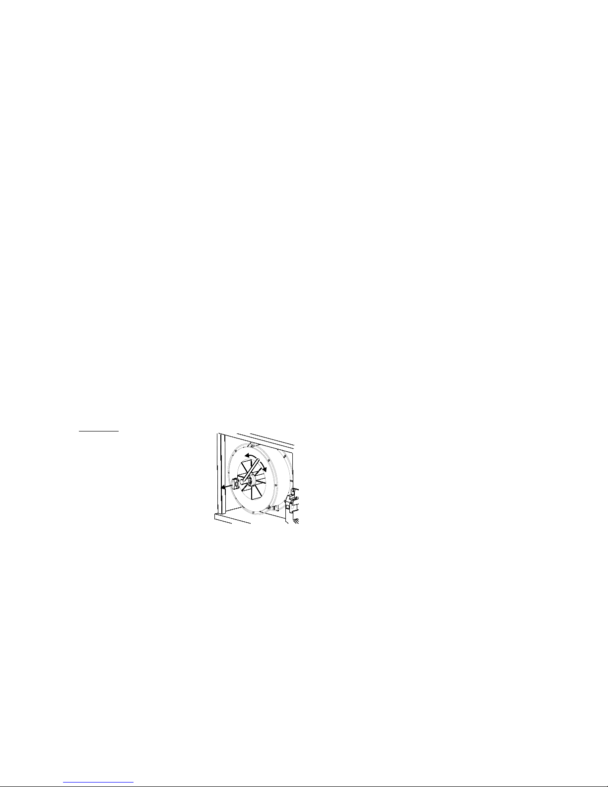
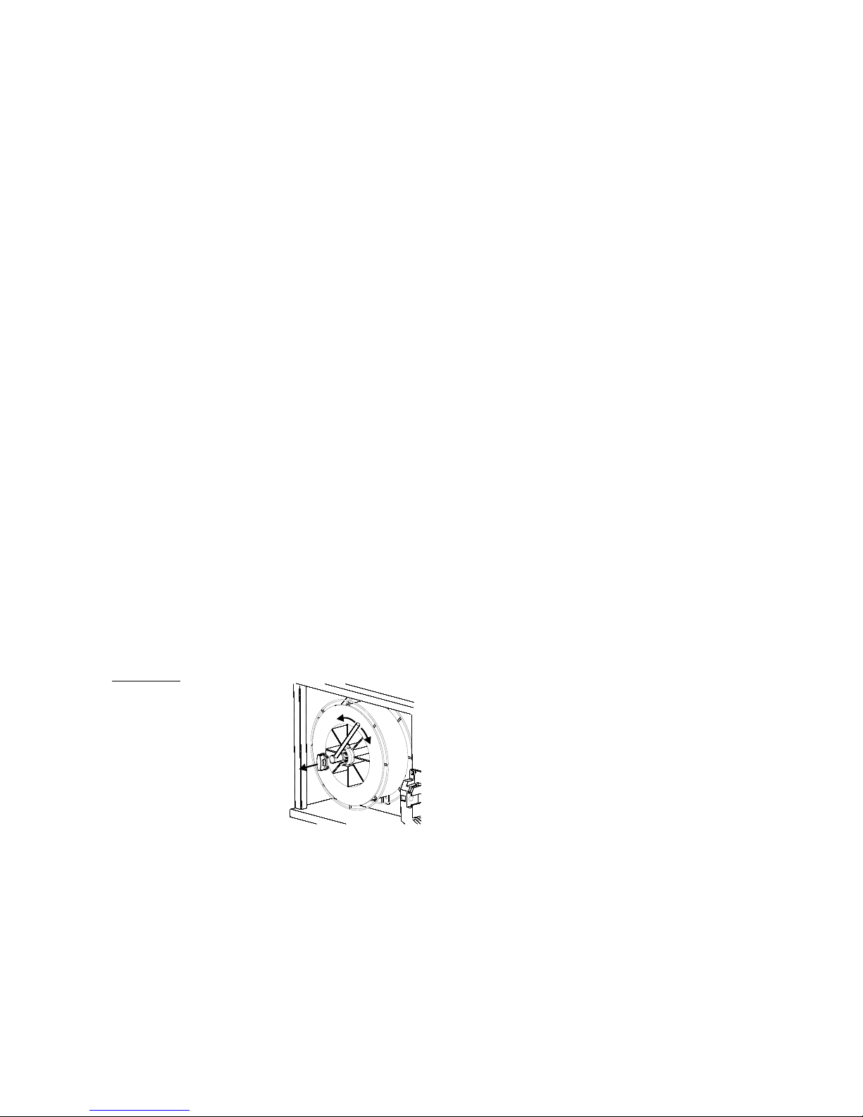
Adjustment of wire brake
The wire brake must ensure that the wire reel brakes
sufficiently quickly when welding stops. The required
brake force is dependent on the weight of the wire reel
and the maximum wire feed speed. A brake torque of
1.5-2.0 Nm will be satisfactory for most applications.
Adjustment:
- Dismount the control knob
by placing a thin screw
driver behind the knob
and thereafter pull it out
- Adjust the wire brake by
fastening or loosening the
self-locking nut on the
axle of the wire hub
- Remount the knob by
pressing it back into the
groove.
Trolley with automatic mains voltage transition
(Special equipment)
Machines supplied with autotransformer can be
connected to the following mains supplies:
3*230V, 3*400V, 3*440V og 3*500V.
Press the power switch (13) to turn on the
autotransformer (green indicator light). The built-in
energy saver function will automatically turn off the
welding machine after 40 minutes of inactivity. Press
the button (14) to turn on the machine again (red
indicator light).
The energy saver function can be permanently
disconnected by a Migatronic technician.
Switch on Press Weld
The machine is almost ready to use
Switch on the welding machine
on the main switch (2)
Select internal/external control (see page 24)
Select welding program
A welding program must be selected in relation to
welding wire, shielding gas or possible electrode.
Please read how this should be selected on your
welding machine in the quick guide.
Adjust the welding current
Please read your quickguide
Weld
22
TECHNICAL DATA
POWER SOURCE FLEX2 3000 C
Mains voltage ±15% (50-60Hz) 3x400 V
Fuse 16 A
Mains current, effective 16.5 A
Mains current, max.. 19.0 A (380V) / 18.1 A (400V)
Power, 100% 10.9 kVA
Power, max. 12.5 kVA
No load consumption 40 VA
Efficiency 0.85
Power factor 0.90
Current range 15-300 A
Duty cycle 20°C (MIG) 300A/100%
Duty cycle 40°C (MIG) 270A/100%
Duty cycle 40°C (MIG) 300A/80%
Open circuit voltage 69-76 V
1
Sphere of application
S
2
Protection class IP 23
Standards
EN/IEC60974-1
EN/IEC60974-2
EN/IEC60974-5
EN/IEC60974-10 (Class A)
Dimensions (HxWxL) air cooled/water cooled 90.6x52.4x92.5 cm/105.1x52.4x92.5 cm
Weight air cooled/water cooled 58 kg/69 kg
WIRE FEED UNIT INTERNAL COOLING UNIT
Wire feed speed 0.5-30 m/min Cooling efficiency (1.0 l. flow) 1100W (1.0 l/min)
Torch connection EURO connection Tank capacity 3.5 litres
Wire-reel diameter 300 mm Flow 1.2 bar – 60°C 1.75 l/min
Duty cycle 40°C 420A/100% Pressure max.. 3 bar
Duty cycle 40°C 500A/60% Standards EN/IEC60974-2
2
Protection class IP 23
Wire diameter 0.6-2.4 mm
Gas pressure max. 0.5 MPa (5.0 bar)
Standards EN/IEC60974-5
EN/IEC60974-10 (Class A)
FUNCTION PROCESS VALUE RANGE
Selection of trigger mode MIG/MAG 2-times/4-times
Control of current/voltage/ wire feed speed - local/torch control/remote control
Wire inching MIG/MAG Yes
Torch cooling - water cooled/gas cooled
Hot-start % MMA 0.0% – 100.0%
Hot-start-time MMA 0.0 – 20.0 s
Arc power MMA 0.0 – 150.0%
Gas pre-flow MIG/MAG 0.0 – 10.0 s
Soft-start MIG/MAG 0.5 – 24.0 m/min
Hot-start Synergic -99% – +99%
Hot-start-time Synergic 0.0 – 20.0 s
Slope down Synergic 0.0 – 10.0 s
Stop Amp Synergic 0 – 100%
Stop Amp time Synergic 0.0-10.0 s
Burn back MIG/MAG 0 – 30
Gas post-flow MIG/MAG 0.0 – 20.0 s
Sequence timer / Spot welding time MIG/MAG 0.0 – 50.0 s
DUO PlusTM efficiency MIG/MAG 0 – 50%
DUO PlusTM time MIG/MAG 0.1 – 9.9 s
Electronic choke -5.0 – +5.0
Sequence 9 sequence steps
1
S This machine meets the demand made for machines which are to operate in areas with increased hazard of electric chocks
2
Equipment marked IP23 is designed for indoor and outdoor applications
23
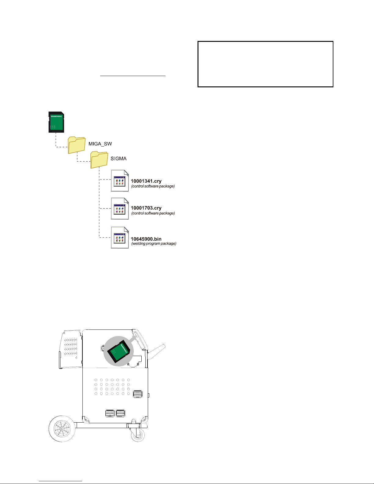
SOFTWARE
In case of exchange of the control unit, software must
be reloaded, using an SD card.
Latest software can be downloaded under Product
software at www.migatronic.com/login. Save the
software on an SD card containing the folders and one
or more of the files shown below.
To order SD card, use item no. 12646000.
Software reading
Insert the FLEX
2
3000 Compact SD-card in the
slide in the right side of the machine.
Turn on the machine.
The display flashes shortly with six lines.
Wait until the set current is displayed.
Turn off the machine and remove the SD card
The machine is now ready for use.
If the SD-card contains software for other units e.g.:
10020115.cry RWF
10020113.cry RCI
These units will be updated if they are connected to
the CAN network.
Please note that this update will be longer in time, so
please do not turn off the machine until the standard
control panel will be displayed at
FLEX
2
3000 Compact.
Licence SW
If additional licences for programs or special functions
have been bought, then the MigaLic.dat files should
be read by the machine in the same way as SWpackages. Please remember to save a backup file.
The MigaLic.txt file contains information about
machine licence number and containing licences at
the SD-card.
All machine user settings are deleted when
the file 10645900.bin has been inserted.
Therefore, always remove the SD-card from the
machine after the software update. Thereby,
continuous software update is avoid each time
the machine is turned on.
24
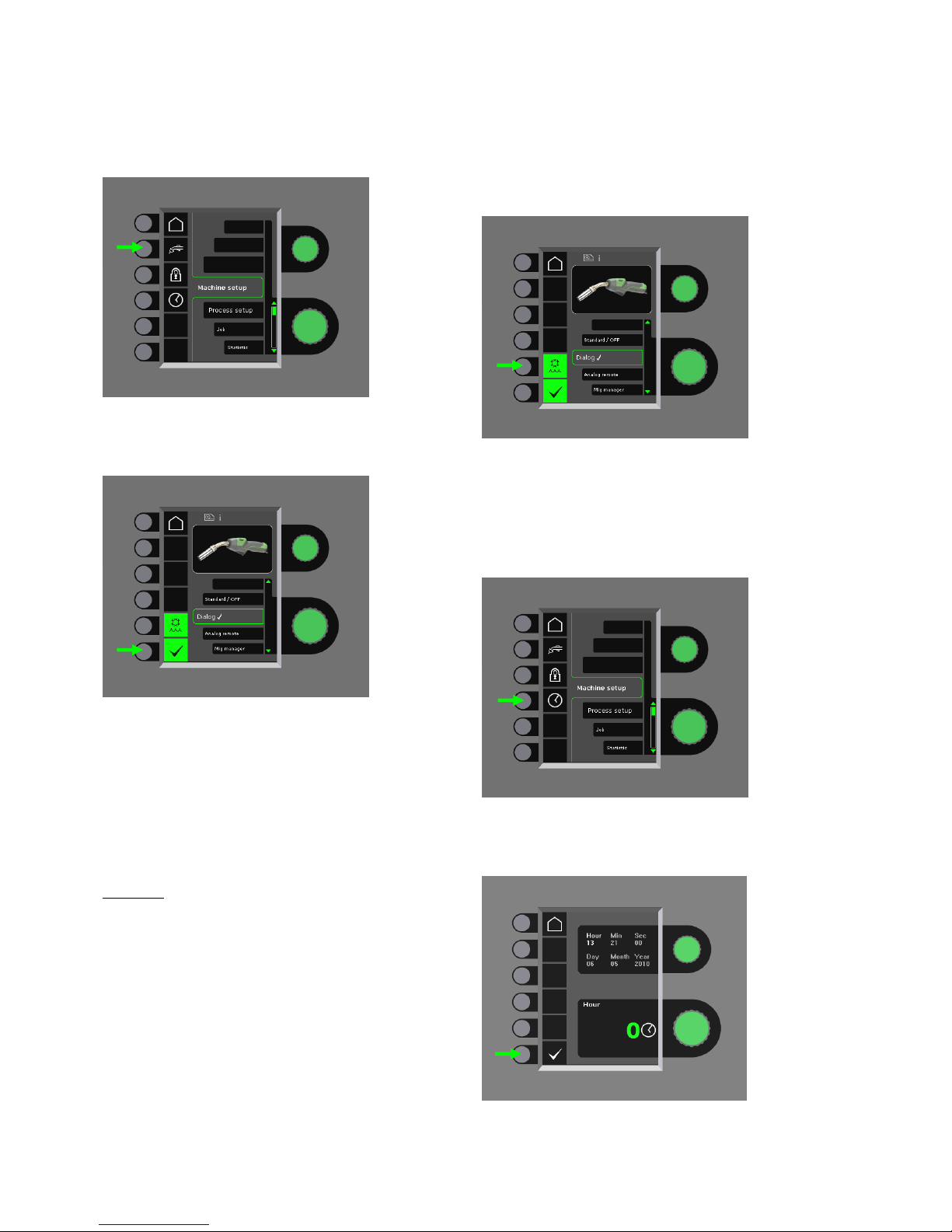
SPECIAL FUNCTIONS
Configuration of internal/external control
It is possible to configure internal and external control
by pressing the following key pad in the Machine
Setup-menu:
Turn the lower control knob until the requested
configuration is displayed. Press the -knob to
confirm the selection (selected configuration is
indicated by ):
Dialog torch:
Current can be adjusted both on the control panel and
on the control wheel on the welding torch. Voltage trim
can be adjusted from the control panel.
Sequence torch:
3 or 7 sequences are automatically defined when
selecting between 3 or 7 sequence torch. Change of
sequences can only be carried out from the torch. All
other settings are carried out internally on the control
panel.
IMPORTANT!
It is not possible to shift between sequence number 1
to 7 (1 to 3 at the ERGO model XMA) if the wrong
sequence torch has been selected. Please select a
suitable type from the list.
Remote control:
Current can be adjusted both on the control panel and
from the control knob on the remote control.
Voltage trim can only be adjusted from the remote
control.
MIG Manager
®
:
Read quick guide for MIG Manager
®
Connection/disconnection of water cooling
(MIG/MAG)
The water cooling function will ensure protection of the
water-cooled torch. The water cooling will
automatically be activated when welding is started and
stops automatically 3 minutes after welding has been
completed. Water cooling is activated by pressing the
following key pad:
When a MIG Manager
®
is connected, it will
automatically control the water cooling function and
disable this configuration.
Setting of time
It is possible to set the time by pressing the following
key pad in the Machine Setup-menu:
It is important to set the correct time, if logging of e.g.
errors should be used. The setting is confirmed by
pressing the following key pad after the setting is
completed:
25
Lock function (Option)
It is possible to select the requested lock level by
pressing the following key pad in the Machine Setupmenu:
Functions are locked to the selected lock level by
inserting the SD-lock-card and unlocked by reinserting
the SD lock-card.
Recall of factory settings
This results in a total reset to factory settings:
Display of licenses
It is possible to get a complete overview of the number
of licenses:
Display of software versions/licence number
Software versions/licence number can be displayed by
pressing the following key pad in the service menu:
Licence number is used for purchase of additional
licences. It is important to state the correct number by
placement of order and to differ between numbers,
small and capital letters.
26
Cable compensation (calibration of resistance in welding hose)
The surface of the workpiece must be clean
to ensure good contact with the torch.

27
ERROR HANDLING
FLEX
2
3000 Compact has a sophisticated built-in
selfprotection system. The machine automatically stops
the gas supply, interrupts the welding current and stops
the wire feeding in case of an error.
Selected errors:
Torch cooling fault
Cooling fault is indicated on machines equipped with
water flow kit in case of no circulation of the cooling
liquid due to faulty connection or choking.
Check that the cooling hoses are correctly connected,
top up the water tank and check welding hose and
branches. The cooling fault is cancelled by pressing
shortly on the –key pad.
Gas control fault
Gas fault exists due to a to low or high pressure on the
gas flow.
Make sure that the pressure on the gas flow is higher
than 2 bar and less than 6 bar, corresponding to 5 l/min
and 27 l/min.
The fault is disconnected by adjusting the manual gas
flow to 27 l/min. The gas fault is reset by a short
pressure on the -key pad.
Error log
All errors are saved in the machine error log in the menu
Service. The error log can be distributed, when inserting
a SD-card and pressing the following key pad:
The error log is now saved at the SD-card.
The error log can be reset when pressing the key pad
with the trash bin.
MAINTENANCE
The machine requires periodical maintenance and
cleaning in order to avoid malfunction and
cancellation of the guarantee.
WARNING !
Only trained and qualified staff members can
carry out maintenance and cleaning. The
machine must be disconnected from the mains
supply (pull out the mains plug!). Thereafter,
wait around 5 minutes before maintenance and
repairing, as all capacitors need to be
discharged due to risk of shock.
Wire cabinet
- Regularly, clean the wire cabinet with
compressed air and check if the grooves and
teeth on the wire drive rolls are worn out.
Cooling unit
- Liquid level and frost protection must be checked
and cooling liquid refilled as required.
- Drain the cooling liquid out of the cooling module
and welding hoses. Remove dirt and flush with
pure water in the tank and cooling hoses. Fill up
with new cooling liquid. The machine is delivered
with a cooling liquid of type propan-2-ol in the
ratio 23% propan-2-ol and 77% demineralized
water, which provides an anti-freeze solution up
to –9°C. (See article number in the spare parts
list).
Power source
- Clean the fan blades and the components in the
cooling pipe with clean, dry, compressed air as
required.
- A trained and qualified staff member must carry
out inspection and cleaning at least once a year.
28
ERROR CODES
One of the following mentioned error codes will be displayed if an error occurs during software update.
Error codes for MWF software 10001341.cry
Error code Cause and solution
There is no software present in the
control unit.
Insert a SD card with software in the
control unit and turn on the machine.
SD card is not formatted.
The SD card must be formatted in a
PC as FAT and place the files down on
the card or use another SD card.
SD card contains no software.
See page 23.
SD card has more files of the same
name.
See page 23.
The control unit has tried to read more
data than is accessible in the memory.
1. Insert the SD card again.
2. Replace the SD card.
3. Contact MIGATRONIC Service.
Software on the SD card is locked for
another type of control unit.
Use a SD card with software that
matches your control unit.
Software on the SD card is locked for
another control unit with another serial
number/ bar code.
Use a SD card with software that
matches your control unit.
The internal copy protection does not
allow access to the microprocessor.
1. Insert the SD card in the machine
again.
2. Contact MIGATRONIC Service.
The memory circuit is defective in the
control unit.
Contact MIGATRONIC Service.
The memory circuit is defective in the
control unit.
Contact MIGATRONIC Service.
The file 10001341.cry has an error.
1. Insert the SD card in the machine
again.
2. Exchange the SD card.
Error codes for welding program package
10645900.bin
Error code Cause and solution
There is no welding programs present
in the control unit
Insert a SD card with software in the
control unit and turn on the machine.
See page 23.
SD card is not formatted.
The SD card must be formatted in a
PC as FAT or use another SD card.
It is only possible to have one file with
welding programs.
Make sure that there is only one file
with the number 10645900.bin on the
SD card. See page 23.
The welding program package does
not match this control unit.
Use a SD card with software that
matches your control unit.
The welding program package is
locked for another control unit with
another serial number/ bar code.
Your software package is copy
protected and cannot be used for a
control unit without the correct license.
The control unit is defective
Contact MIGATRONIC Service.
The file 10645900.bin is not present on
the SD card.
See page 23.
The file 10645900.bin has an error.
1. Insert the SD card in the machine
again.
2. Exchange the SD card.
The Sigma folder with files are not
present at the card or are saved
incorrectly.
1. Make a folder
MIGA_SW / SIGMA as described on
page 23 and save the files in the
folder.
2. Exchange the SD card
The internal memory is to small
Welding program package cannot be
loaded
29
Error codes for Power control package 10001703.cry
Error code Cause and solution
The file 10001703.cry has an error.
1. Insert the SD card in the machine
again.
2. Exchange the SD card.
SD card is not formatted.
The SD card must be formatted in a
PC as FAT. Or use another SD card.
The software does not match this
control unit.
Use a SD card with software that
matches your control unit.
DSP-PCB is defective
Contact MIGATRONIC Service
Data transmission error
Turn on and off the machine.
Exchange the SD card if the error is
displayed again. Contact your dealer
if necessary.
The file 10001703.cry has an error.
1. Insert the SD card in the machine
again.
2. Exchange the SD card.
DSP-PCB is defective
Contact MIGATRONIC Service
The SD card contains too many files
with 10001703.cry-data
SERVICE
Test
Test functions which should only be used by the
service technician in connection with troubleshooting
of the machine.
The following test can be carried out:
- Turn on cooling unit
- Turn on fan
- Turn on magnetic valve
- Turn on wire feed motor
The following information can be displayed:
- Power source temperature
- DC link voltage
- IAC module installed
WARRANTY CONDITIONS
Migatronic continuously carries out quality control
throughout the manufacturing process as well as
check of the complete units through comprehensive
testing.
Migatronic provides warranty in accordance with the
following provisions, by correcting errors and defects
on units, that demonstrably and within the warranty
period may have been caused by faulty material or
workmanship.
The warranty period is 24 months for new welding
machines, 12 months for new accessories and
6 months for spare parts. The warranty period is
calculated from the date of invoice to the end user
from Migatronic or Migatronic’s dealer/distributor. In
the case of sales through Migatronic’s
dealer/distributor, the warranty period expires in any
event within 36 months for new welding machines and
30 months for spare parts from the date of invoice
from Migatronic to the dealer/distributor. This
extension in no way extends the warranty period. The
original invoice is proof of the warranty period.
Welding torches are considered as wearing parts, and
only errors and defects found within 6 weeks upon
delivery and due to faulty material or workmanship,
will be considered under warranty.
Warranty repairs neither extend nor renew the
warranty period.
Any transport of goods or persons in connection with a
warranty claim is not covered under Migatronic’s
warranty obligation and will therefore be at the buyer’s
expense and risk.
Please also refer to www.migatronic.com/warranty

30
 Loading...