

Page 1

Full HD Digital & Analog Signal
Mixed Video Switcher
User Manual V1.1
△!
MAGNIMAGE
Before using this Mixed Video Switcher, please read this
manual carefully and preserve for future reference.
MIG-630C series
Page 2

Statements
Without the written permission, any unit or individual could not
copy, reproduction or translate the book or part of it. Also could
not transmit it in any form or any way(electronic, mechanical,
photocopying, record or other way) for any business and profitable
purpose.
The product specifications and information mentioned in this
manual is just for reference, will not give prior notice if there is any
updated. Unless there is a special agreement, it is just used as
guidelines. All the statements or information in this manual shall
not constitute any form of guarantee.
Page 3

BRIEFS ················································································································· 1
TRADEMARK CREDIT ·································································································· 1
ABOUT SOFTWARE ···································································································· 1
FEATURES ················································································································ 1
USING DIRECTIONS ····························································································· 3
INCLUDED ACCESSORIES ····························································································· 3
PORT EXPANSION ······································································································ 4
SAFETY TIPS ············································································································· 5
FEATURES ············································································································ 6
OVERVIEW ·············································································································· 6
TECHNICAL SPECIFICATIONS ······················································································ 10
USAGE MENU ···································································································· 11
NON-MENU STATE INTRODUCTION ··································································· 12
MAIN MENU INTRODUCTION ····················································································· 13
Main Menu ····································································································· 13
Image Set Submenu ························································································ 14
Import Configuration ······················································································ 15
Output Configuration ····················································································· 16
Image Transition ····························································································· 18
VGA Adjust······································································································ 19
PIP ·················································································································· 20
Image Crop ····································································································· 21
Chroma Key Function ······················································································ 22
LOGO Setting ······························································································· 23
Test Pattern ···································································································· 25
QUICK APPLICATION ························································································· 28
PORT INTRODUCTION ······························································································ 28
SIGNAL SWITCHING ································································································· 28
Shortcut Introduction ····················································································· 29
MODEL INTRODUCTION ···················································································· 33
Contents
Page 4

WARRANTY EXPLANATION ················································································ 33
WHOLE UNIT WARRANTY PERIOD ·············································································· 33
THE WARRANTY PROVISIONS ····················································································· 33
Page 5
1
Thanks for your purchasing our full HD Digital & Analog mixed signal video
switcher. Do hope you can enjoy the experience of the product performance.
The design of the LED video processor conforms to international and industry
standards. But if with improper operation, there will be a personal injury and
property damage. In order to avoid the dangerous, please obey the relevant
instructions when you install and operate the product.
Trademark credit
VGA and XGA are the trademarks of IBM.
VESA is a Video Electronics Standards Association's trademark.
Even if not specified company or product trademarks, trademark has
been fully recognized.
About software
Do not change, decompile, disassemble, decrypt or reverse engineer the
software installed in the product, these acts are illegal.
Features
available for 10 signals input at a time(can be extended to 12);
available for 3 image output(DVI+VGA port, including 1 main output and
2 PVW
available for 1 Logo input and 1 black background input
available for multi switch effects including instant switch, fade in and
fade out, and edge dissolve, and the switch time is adjustable
Briefs
Page 6

2
available for overlying, cutout synthesis function, and can easily achieve
caption overlying and image synthesis effects
internal multi image layer handling,and available for 3 image output at a
time at most
available for storage and invoking of multi-templates
Page 7
3
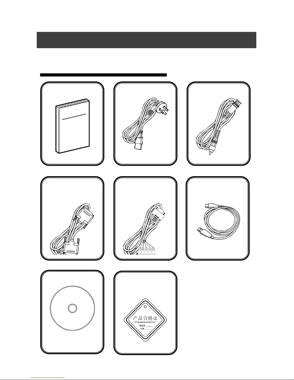
Included Accessories
Using directions
Using manual
Power line
CVBS cable
DVI signal cable
USB Cable
Compact Disk
5BNC-VGA
switching line
Certificate of
Quality
Page 8
4
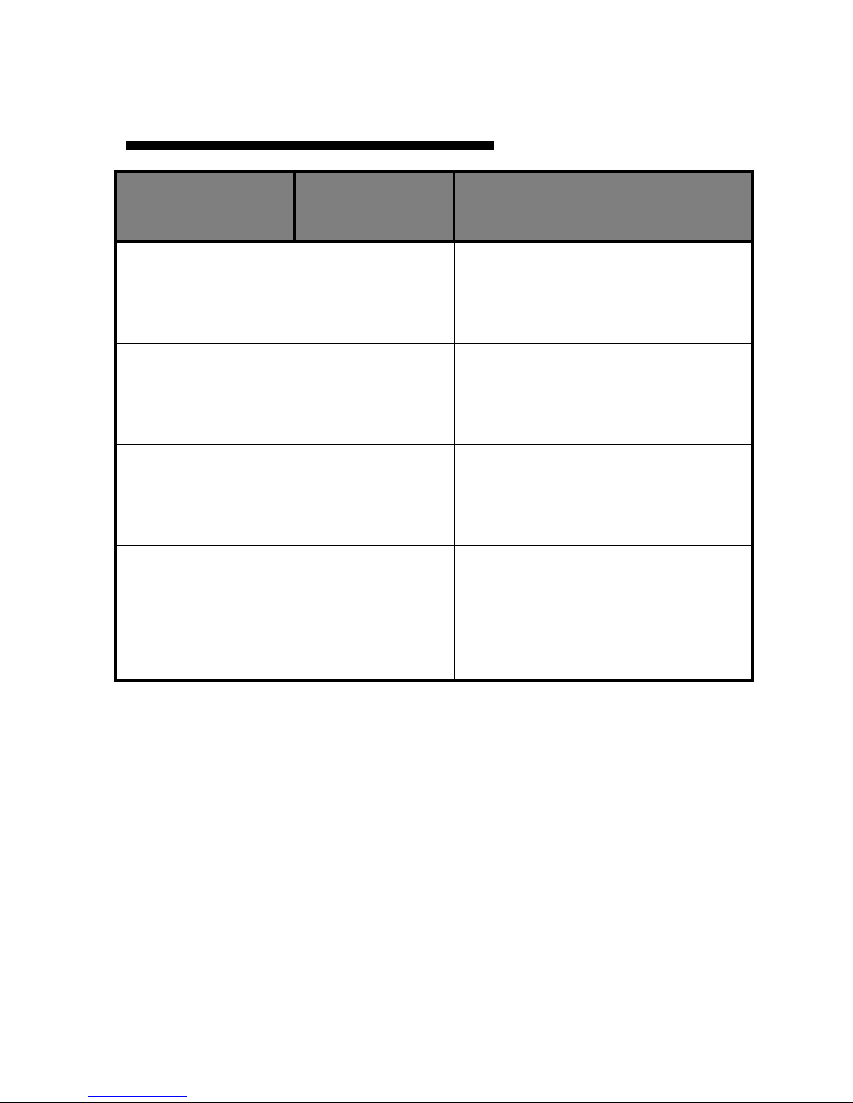
Port Expansion
Name
Corresponding
product model
Explanation
One external
expandable SDI
input
MIG-630CS1
External one channel SDI input
Two external
expandable SDI
inputs
MIG-630CS2
External two channel SDI input
One external
expandable DVI
input
MIG-630CD
External one channel DVI input
One External
expandable SDI
input and one
DVI input
MIG-630CSD
External one channel SDI input and
one channel DVI input
Page 9

5
Safety Tips
This product power supply input voltage range is from 110~240VAC,
50/60Hz, please use the correct power.
Please make sure that all power cables are unplugged when connecting
or disconnecting any signal lines or control lines.
Make sure that all signal and power cables are unplugged when adding
hardware to the products or removing the hardware devices in this
product.
Please turn off the switcher power supply, and release the static
electricity from your body by touching a grounded surface before
making any hardware operation.
This product must be used in a clean, dry, ventilated environment. This
product cannot be used in environments of high temperature and
humidity.
This product is electronic products which should be kept away from fire,
water, inflammable and explosive dangerous goods.
This product has high-voltage components. Please do not open the case
or conduct any self-maintenance to this equipment.
Immediately turn off the power switch should there any smoke, odor, or
abnormal conditions occur and contact your dealer.
Page 10

6
Overview
MIG-630C series is the video switcher developed especially for display
systems. It adopts industry-leading image processing chip with 12
internal digital processing, making images clearer and colors richer.
Its advanced interlace moving image adaptive processing technology
can eliminate the trailing and jaggies of video image motion. For normal
PAL / NTSC video, the output image is more crisp and clear. For HD 1080i
signal, the output of image detail is clearer and colors richer, making the
image quality in the industry-leading level.
The complete video interface includes 6 channel VGA port, 6 channel AV
port, one SDI expansion port, one digital signal expansion port and 3
signal output interface, each contains one DVI and one VGA output,
achieving multi-channel analog digital mixed- signal input and the mixed
independent output of multi-channel analog and digital signal.
The product supports a variety of switching mode including flash switch,
fade-in and fade-out, wipe and edge of the dissolve, etc. The switching
time is adjustable which is able to meet the requirements of the various
occasions.
Features
Page 11

7
Multi-layer processing technology is set in the product which can open
three screens at the same time, and support 1 channel Logo input and
black input.
The product supports graphics overlay and matting function, facilitating
the achievement of a subtitle overlay and image synthesis.
The product’s man-machine interface is friendly which is easy and fast
to operate.
The machine is pure hardware architecture, and its work is stable and
reliable.
Page 12

8
E.M.
DVI1~DVI4
VGA1~VGA6
AV1~AV6
Video Input Port
Expandable Input Port (One
Channel SDI Extendable and
One Digital Video Interface)
DVI Input Port (DVI-D
6 Channel VGA Input Port
6 Video Input Port
VGA1~VGA3
DVI1~DVI3
Video Output Port
3 Channel VGA Output Port
3 Channel -DVI Output Port
Rear panel introduction
Page 13
9
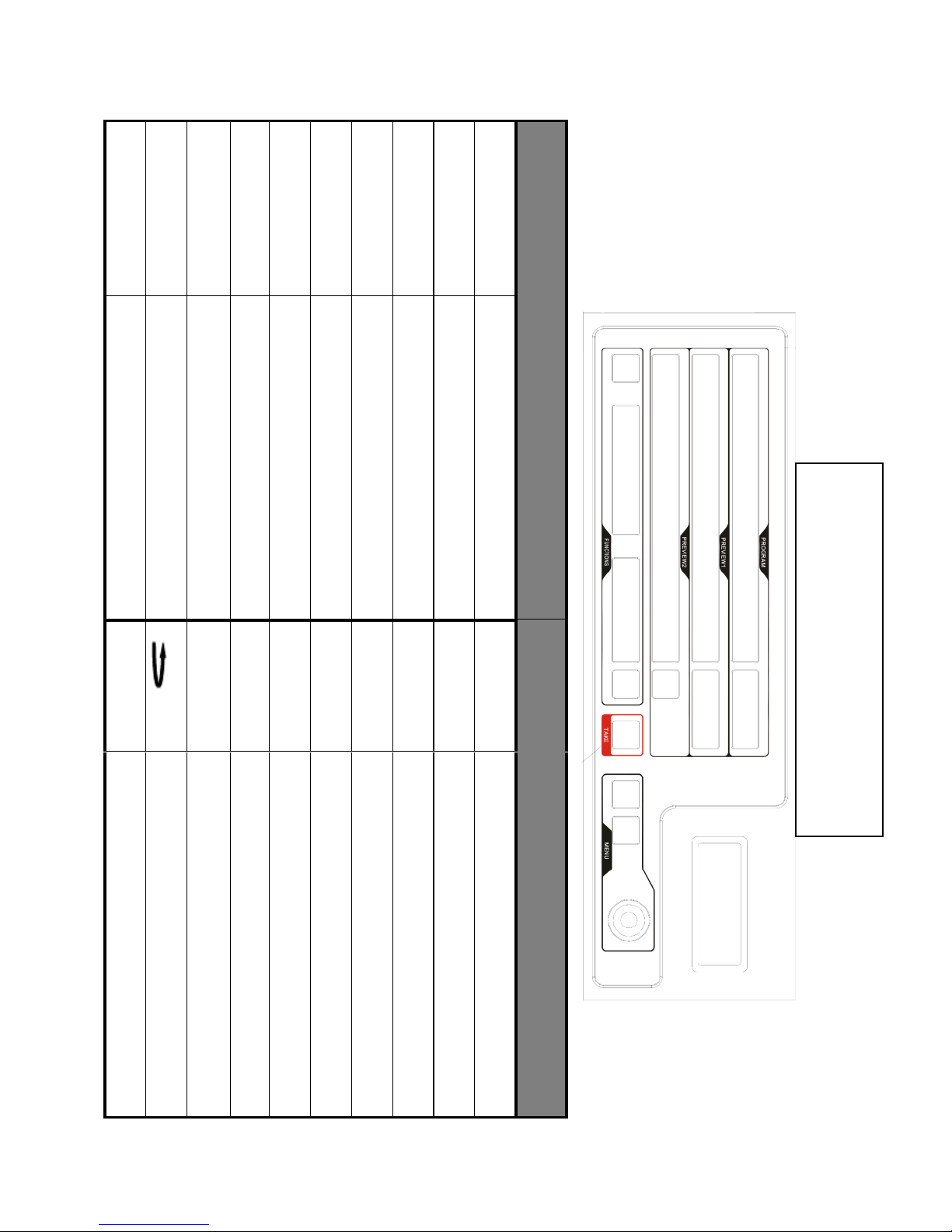
EFFECT1
POSITION
SIZE
Multi Preview
PIP2
PIP1
LOCK
E.M
SDI
1~10
Key Description
Switch effect shortcut 1
Output image location adjustion
Output image size adjustion
Multi-preview shortcut key
Start picture in picture 2
Start picture in picture 1
Lock key
Expand module input choosing
SDI Input signal choosing key
10 channels input signal
knob
OK
TAKE
MODE
BLACK
LOGO
FADE
CUT
EFFECT2
Menu key
backspace
Confirmation key
Switch key
Template selecting key
Blackground selecting key
LOGO selecting key
Fade in and fade out key
Instant switch key
Switch effect shortcut 2
Front panel introduction
Page 14
10
Technical Specifications
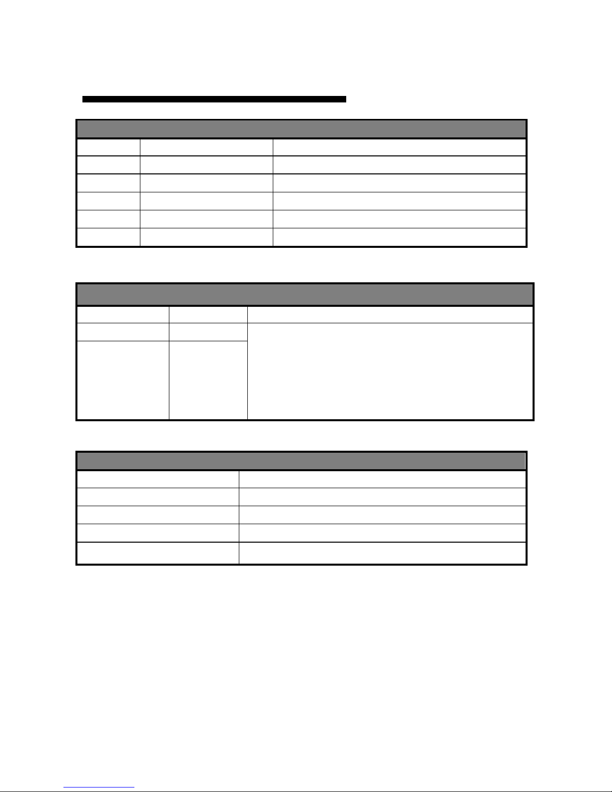
Input Index
Port
Channel(s)
Resolution Specifications
AV 6 PAL/NTSC
VGA
6
VESA Standard
DVI
4
VESA Standard (Support 1080i Input)
SDI
1 (Extendable Port)
480i,576i,720p,1080i/p(3G SDI)
E.M
1 (Extendable Port)
SDI or DP Port Extendable
Output Index
Port
Channel(s)
Resolution Specifications
VGA
3
1024×768/60Hz
1280×1024/60Hz
1440×900/60Hz
1600×1200/60Hz
1920×1080/60Hz/50Hz
1920×1200/60Hz
DVI
3
Machine Specification
Input Power
110~240VAC,50/60Hz
Machine Power
80W
Operating Temperature
0~45℃
Dimensions
485mm ╳ 345mm ╳ 136mm
Weight
5.5 Kg
Page 15

11
MIG-630C series uses a highlight high contrast LCD to display the user menu.
Under the conditions of user not having the operation or the operation timed
out, the LCD screen will display the non-menu state. If you use the buttons on
the front panel to set the machine, LCD screen will display the appropriate
menu according to user’s operation, prompting users to operate better,
faster and more intuitively.
The following will combine the LCD screen display and front panel buttons to
introduce you to the menu system of series MIG-630C in detail.
Usage Menu
Page 16

12
After opening the power of the MIG – 630C series, and during the system’s
startup, the boot interface will be displayed on the left of the front panel LCD
screen. After the start up, the screen will show the current state of the
machine as shown below:
There is a total of four aspects in the figure above, described as follows:
number of
rows
Explanation
First Row
The main output channel shows the input signal channel, the
signal type and its resolution.
Second Row
Pre-monitoring channel displays the input signal channel, the
signal type and its resolution.
Third Row
Pre-monitoring double-channel display shows the input signal
channel, signal type and its resolution.
Fourth Row
Resolution of three-channel output.
Note: #+figure, indicate No. of each input port, corresponding to the No. Of
the rear panel.
Non-Menu State introduction
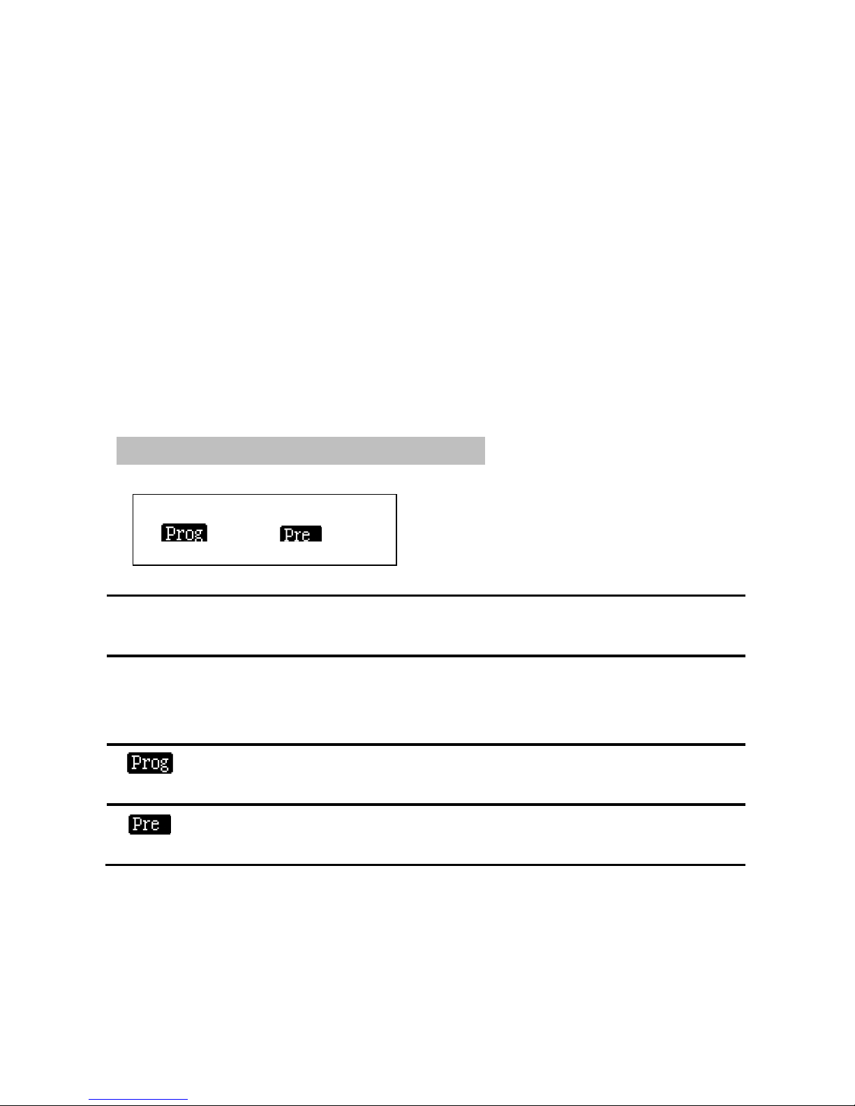
Prog
Output Resolution: 1920x1080 60Hz
Pre1
Pre2
#1
VGA
1920x1080
60Hz
#2
#7
VGA
DVI
1920x1080
No signal
60Hz
Page 17
13
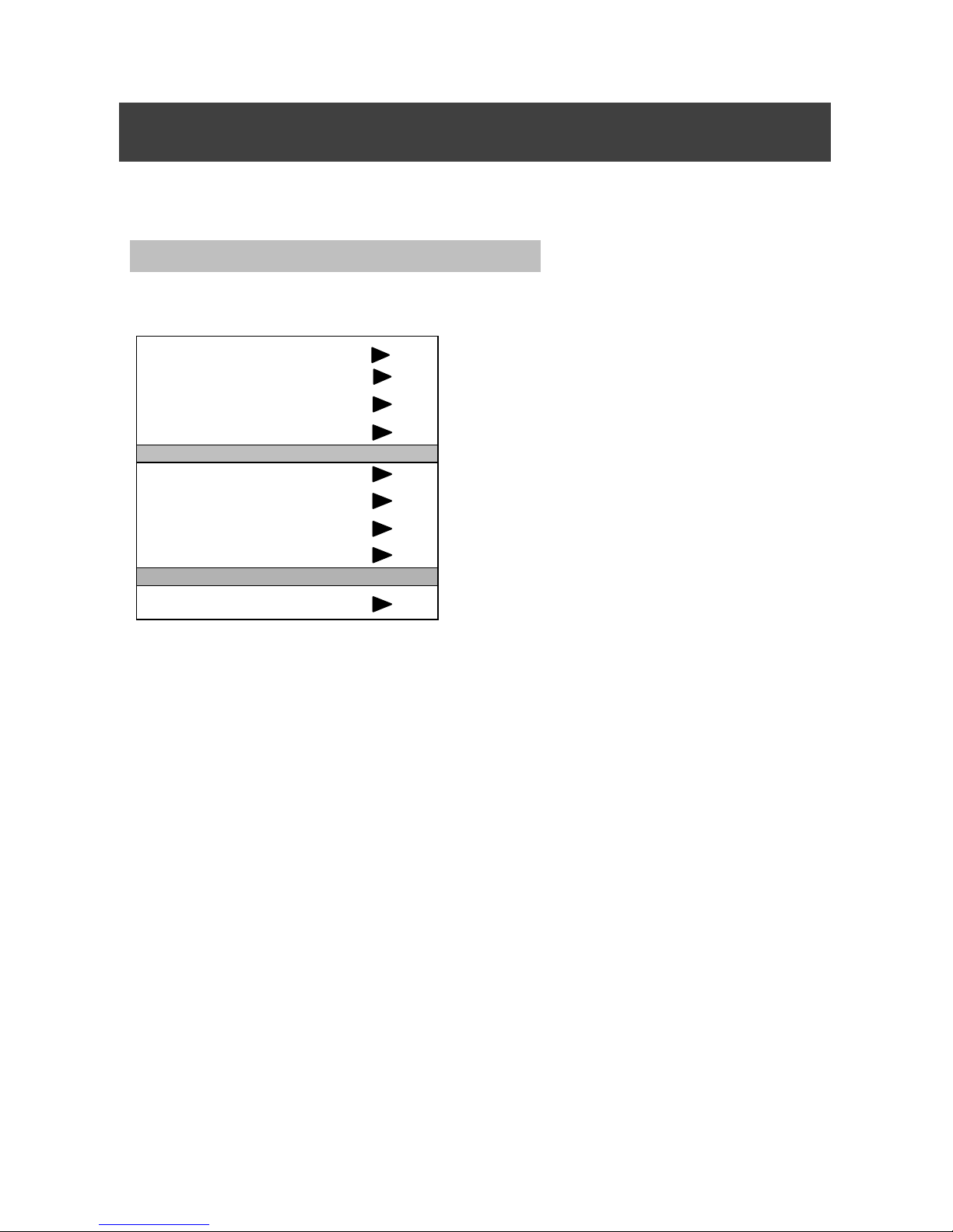
Use "OK" button in the main menu to return and the knob button to
select and adjust various projects. The operation has a fixed mode,
please see the table below:
Main Menu
In the non-menu state, press "knob" and the menu system will enter the
main menu and what displayed on the LCD screen will be shown as below:
Image Settings
Input Configuration
Output Configuration
Picture Switching
VGA Adjust
PIP
Image Crop
Chroma Key Function
Function
By rotating the knob to select the option you want to perform and then tap
the knob or "OK" button to enter the option to operate. Press the "Back" key
to exit.
Main menu introduction
Page 18
14
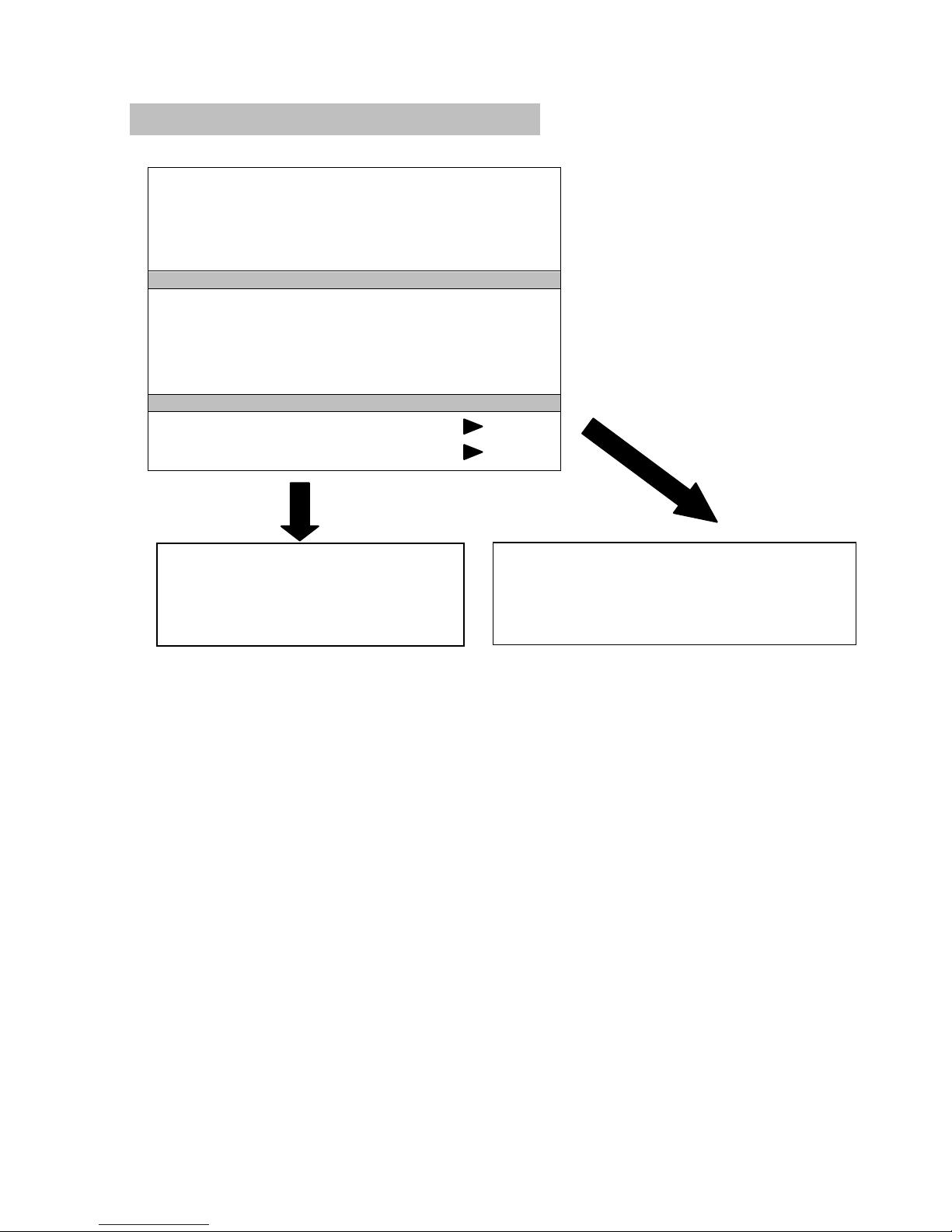
Image Set Submenu
Image Mode
Standard
Brightness
50
Contrast
50
Color
50
Hue
50
Acuteness
12
VGA Enrichment
Off
DVI Enrichment
Off
Color Temperature
Image Parameter Reset
color temperature
Standard
Red
50
Green
50
Image parameter reset
Press the OK button to continue
Press return to cancel
Page 19
15
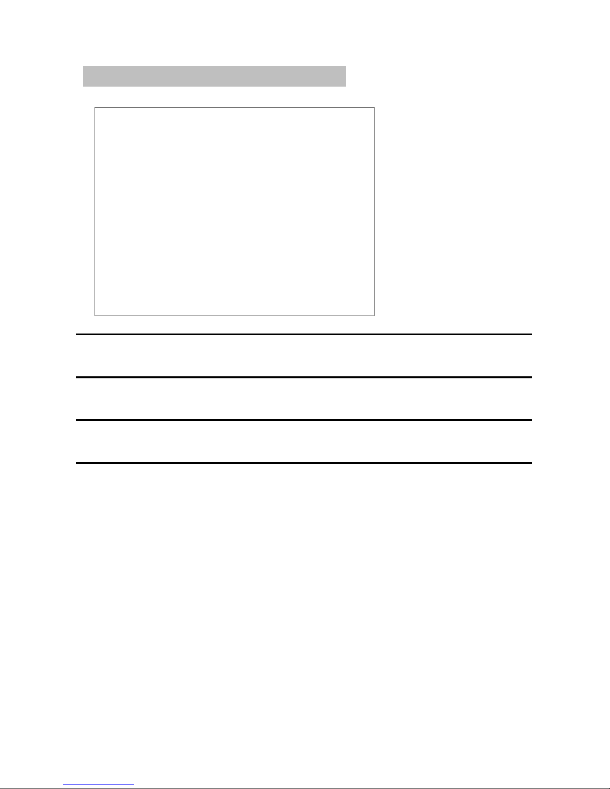
Import Configuration
Button 1
Port #1
Type VGA
Button 2
Port #2
Type VGA
Button 3
Port #3
Type VGA
Button 4
Port #4
Type VGA
Button 5
Port #5
Type VGA
Button 6
Port #6
Type VGA
Button 7
Port #7
Type DVI
Button 8
Port #8
Type DVI
Button 9
Port #9
Type DVI
Button10
Port #10
Type DVI
SDI
Port #11
Type SDI
E.M
Port #12
Type SDI
Button
Refers to the switch keys serial number on the front of the stage
panel
Port
Refers to the units serial number on the rear of switch panel
interface
Type
Refers to the input signal type corresponding to the port(AV,
VGA,DVI or SDI)
Attention should be paid to the port type: for buttons 1 to 6, the
corresponding ports are 1 to 6, and type can be selected VGA or AV; for
buttons 7 to 10, the corresponding ports are 7 to 10, and type can only be
DVI; the port 11 corresponding to Button SDI is an extendable SDI port; the
port 12 corresponding to button EM is another extendable digital interface.
Page 20
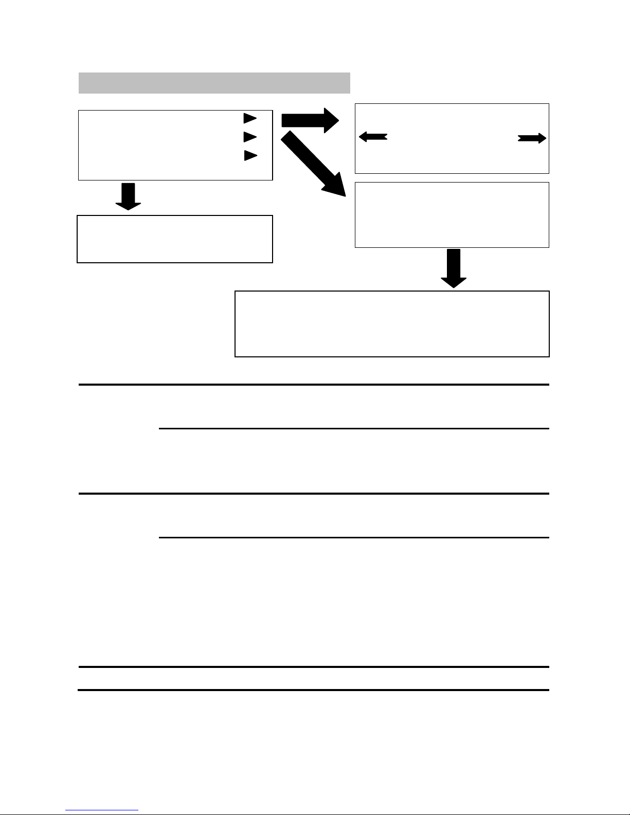
16
Output
Resolution
MIG-630C series supports 7-channel resolution output as
follows:
1024x768/60Hz, 1280x1024/60Hz, 1440x900/60Hz,
1600x1200/60Hz,
1920x1080/50Hz, 1920x1080/60Hz, 1920x1200/60Hz,
Output
window
The output of the three-way window size is as follows: the main
output, pre-monitoring 1 and pre-monitoring 2.
Horizontal Width:The level of points of the output window。
Vertical Height: the vertical points of the output window。
Horizontal Position: the level of starting position of the output
window。
Vertical Position : vertical starting position of the output
window。
Reset
Restore the original size of the window.
Output Configuration
Output
Output Window
Window Reset
The output switch
1024X768 60Hz
PressOK to confirm
Main Output
Pre-monitoring 1
Pre-monitoring 2
Press OK to confirm
Press the back key to return
Horizontal width:1024 Vertical height:768
Horizontal position:0 Vertical position:0
Press OK to confirm
Page 21

17
The selection of the resolution is to set the output resolution to the three
channel output port (the resolution of three channel output port is the same).
Then to individually adjust the screen size and position of the three channel
output signal by adjusting the output window (screen size, position can only
be adjusted within the set resolution range).
Page 22
18
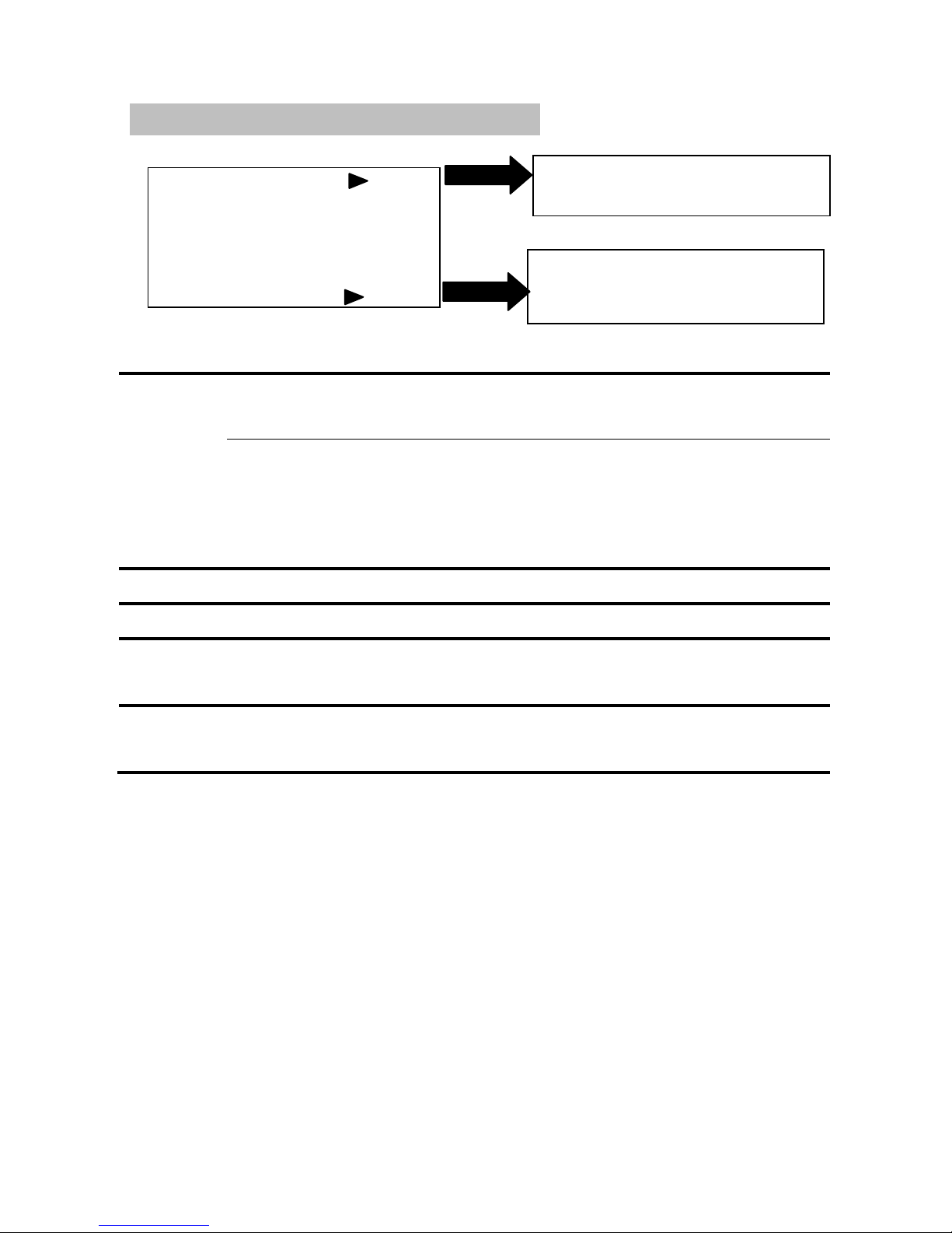
Image Transition
Switch Mode
Effect
CUT
Duration
0
Transition Zone
2
Button Layout
Switch
Mode
Two choices of "Exchange" and "Copy"
Exchange: the exchange between main output window screen
and preview output window screen.
Copy: copy the preview output window screen to the main output
window.
Effect
Effect when switching screen.
Duration
The time spent to switch pictures.
Transitio
n Zone
The unit of screen transition edge is pixels when switching the
screen.
Button
Layout
Deploy the switch effect of “effect 1” and “effect 2”.
MIG-630C series has 16 kinds of transition effects: flash switch, fade-in and
fade-out, right slide, left slide, up slide, down slide, horizontal inward,
horizontal outward, vertical inward, vertical outward, box inward, box outward,
cross inward, cross outward, checkerboard and blinds.
Duration is time spent to switch pictures which can adjust the time between
the two effects of the screen through selecting the cycle time.
Through button configuration it can define the switching effect of "Effect1"
and “Effect2”, and can switch signal directly by tapping the two keys to
select a transition effect.
Switch
Copy
Effect1 Left Slide
Effect2 Shutter
Page 23
19
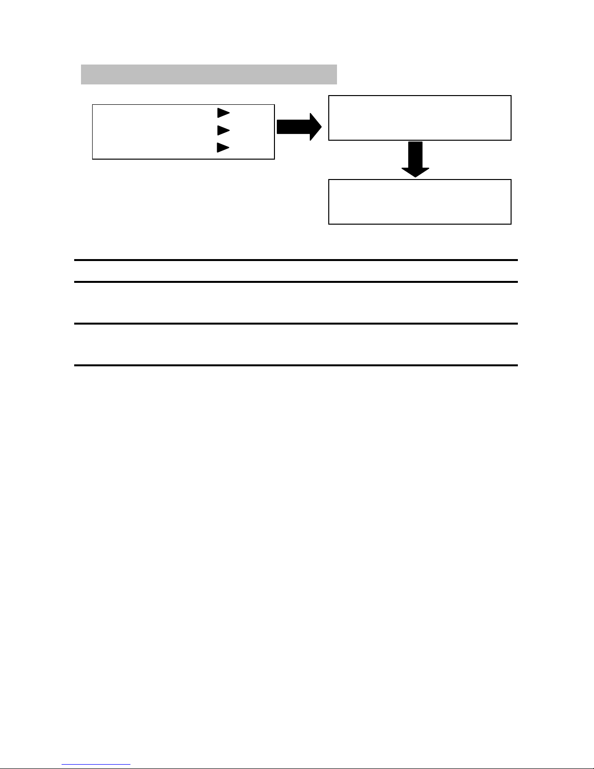
VGA Adjust
Main Output
Pre Monitoring 1
Pre Monitoring 2
Main Output
Correction of the VGA input signal in main output channel
PIP 1
Correction of the VGA input signal in first pre-monitoring
channel
PIP 2
Correction of the VGA input signal in second pre-monitoring
channel
Correcting
………
Corrected
………
Page 24
20
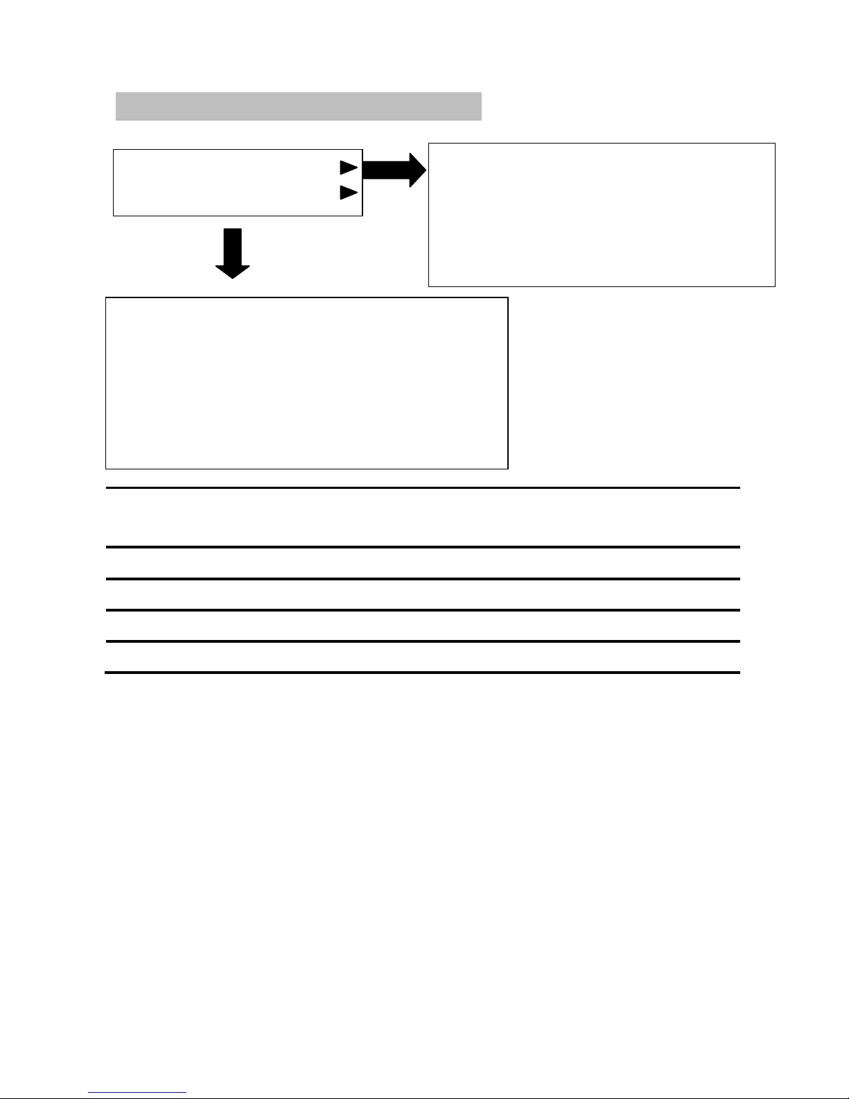
PIP
PIP 1
PIP 2
PIP
Picture in Picture has the function of "open" and "off",
the default is off。
Horizontal Width
Level of the points of output window.
Vertical Height
Vertical points of the output window.
Horizontal Position
Starting position of the output window.
Vertical Position
The vertical starting position of the output window.
First open the picture in picture. Adjust the horizontal width and vertical
height to adjust the size of the PIP. By adjusting the horizontal and vertical
position to adjust the position of the PIP, dual screen or three-screen picture in
picture, picture out picture can be achieved.
PIP 1
On
Horizontal
Width 1024
Horizontal
Position 768
Vertical
Height 0
Vertical
Position 0
PIP 2
off
Horizonta l
Width 1024
Horizontal
Position 768
Vertical
Height 0
Vertical
Position 0
Page 25
21
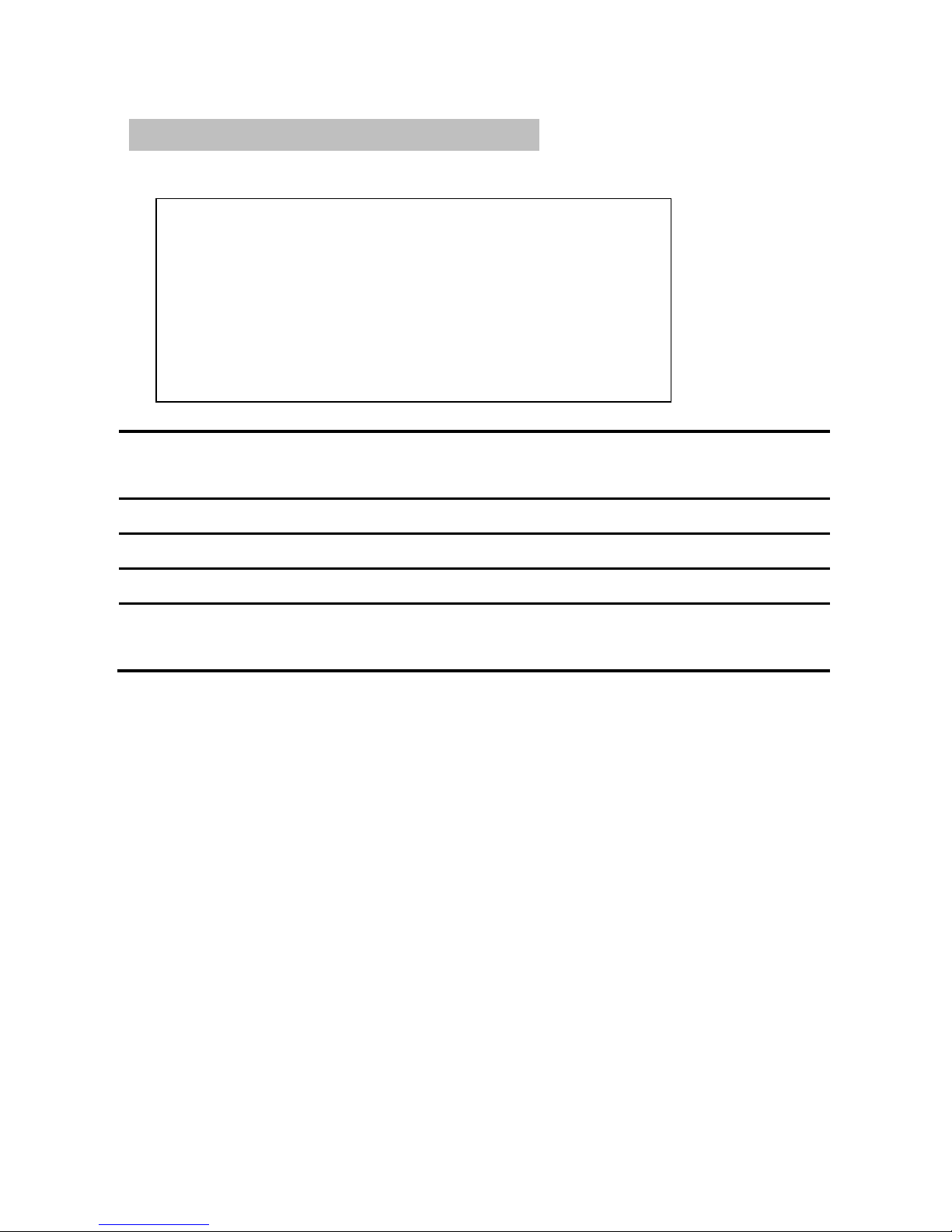
Open "image capture" function. Adjust the horizontal width and vertical
height to determine the level of interception of the image pixels and vertical
pixels. Determine the regional location of the intercepted image through
adjusting the horizontal position and vertical position so that you can cut off
part of the image, such as the black edges from top to bottom in HD movies,
or make screenshots in a region to zoom into full screen.
Image Crop
Port
#10
DVI
Main Output
Image Crop
On
Horizontal
Width 1024
Horizontal
Position 0
Vertical
Height 768
Vertical
Position 0
Image Crop
The image capture has the function of "open" and
"off", the default is off.
Horizontal Width
Interception of the level of image points.
Vertical Height
Vertical interception of image points.
Horizontal Position
Interception of the image starting position.
Vertical Position
Interception of the vertical starting position of the
image.
Page 26
22
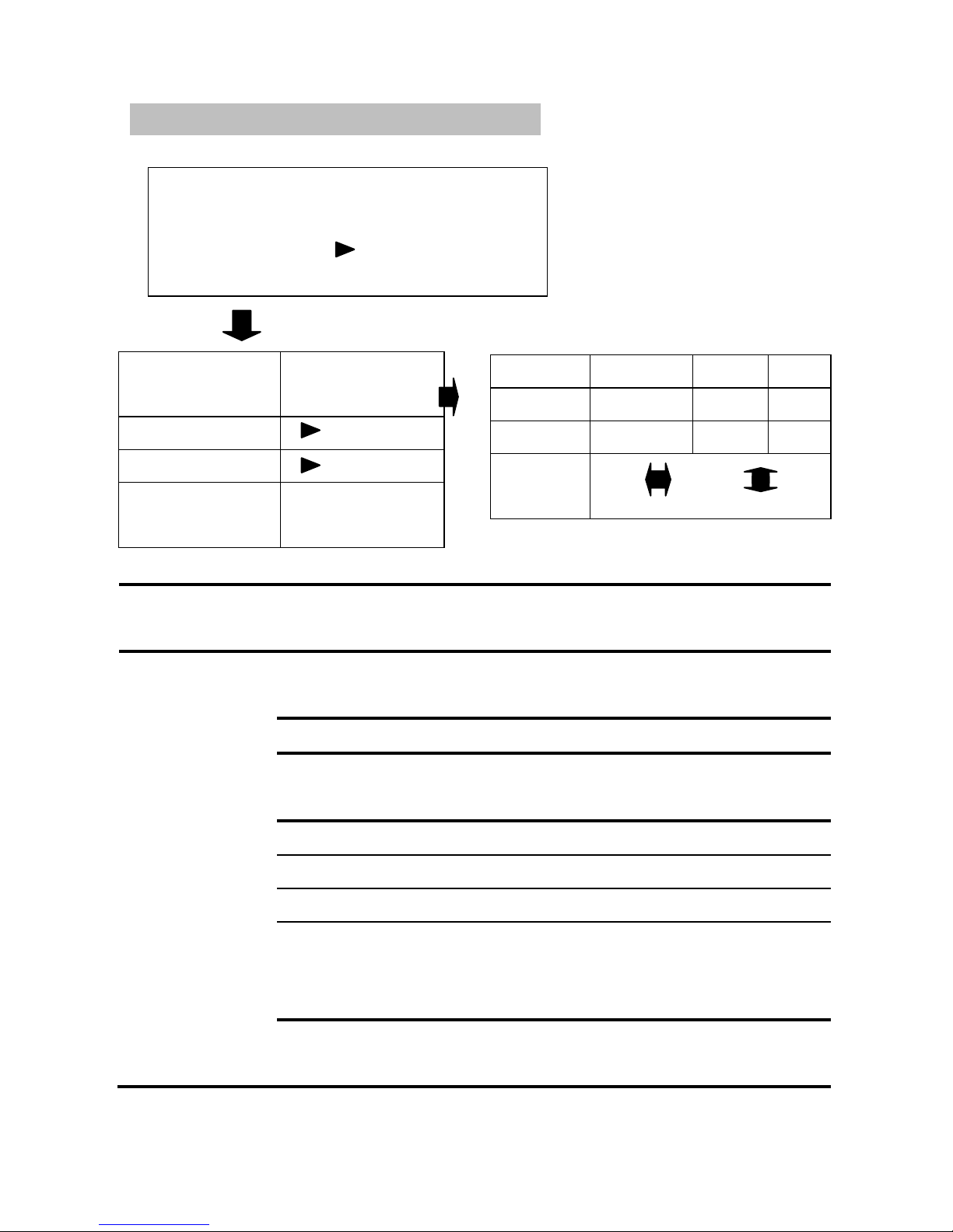
Chroma Key Function
Chroma key
function
Off
Chroma key
settings
Chroma key
function
Chroma key has the function of "open" and "off", the default
is off.
Chroma key
settings
Color settings.
Layer Selection Select the layer screen.
Color Range Select the scope of three primary
colors.
Red Range 0~255
Green Range0~255
Blue Range0~255
Auxiliary Cursor: To move the icon by selecting the "up" or
"down", “left” or “right”.
Color range second switch. "Open" and “off" in the color
range.
Red
(0~0)
Red
0
Green
(0~0)
Green
0
Blue
(0~0)
Blue
0
Auxiliary
Cursor
Layer Selection
Picture in
picture 2
Color range 1
Color range 2
Color range 2
switch
Disable/Enable
Page 27
23
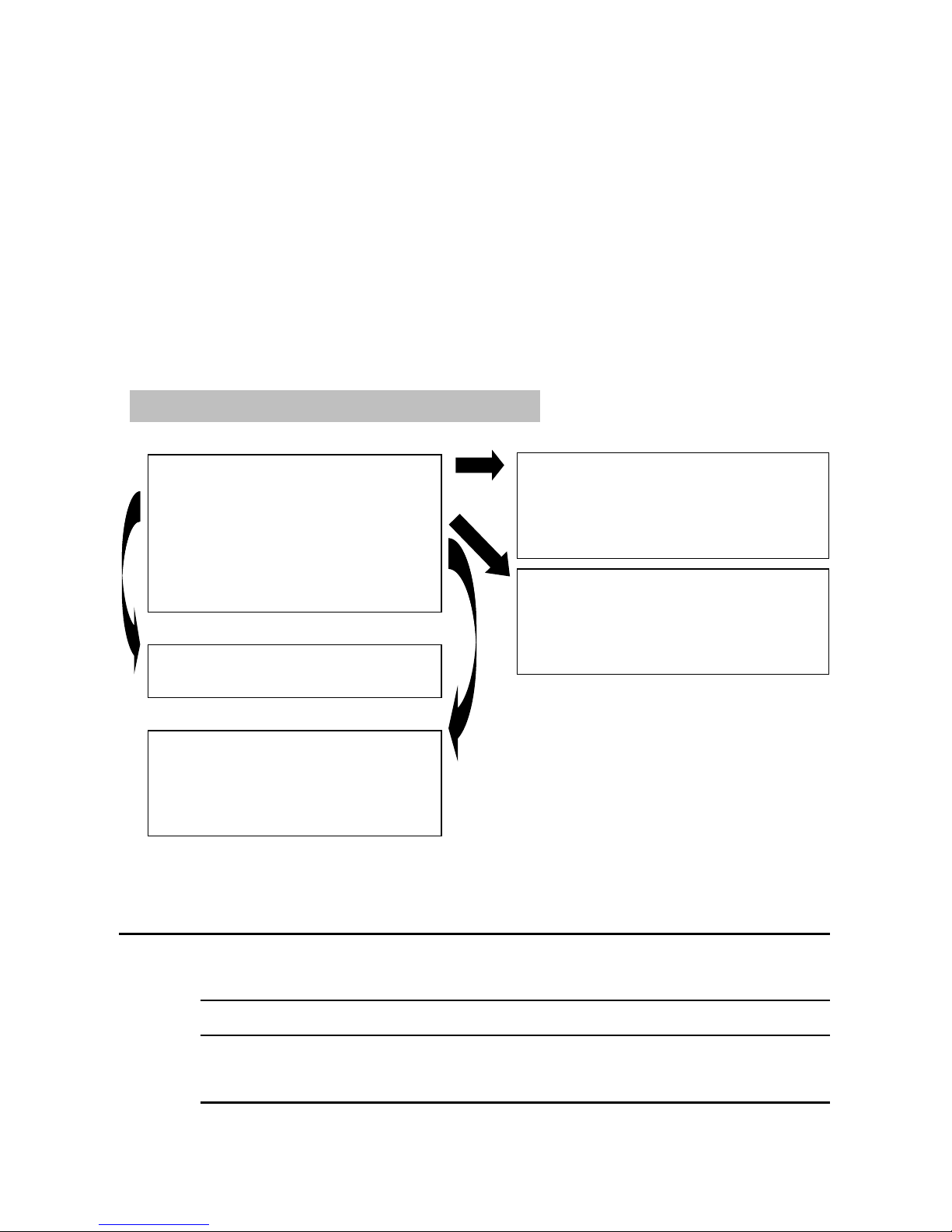
After finishing selecting LOGO layer (PIP 1 or PIP 2), enter color range 1, then
select the color need to be wiped through the auxiliary cursor "left" or "right",
“up” or “down”. Take white LOGO with black background for example. You
can move the cursor to the black areas and press "OK" to erase the black areas
of the LOGO screen. By doing this, the main screen image can float out and
LOGO can thus be embedded in the main screen.
LOGO Setting
Save Logo
►
Clear Logo
►
Load Logo
►
Storage
►
Layer
On Top/
File:
1.BMP ●
Clear
►
1.BMP ●
5.BMP ●
2.BMP ○
6.BMP ○
3.BMP ●
7.BMP ○
4.BMP ●
8.BMP ○
Save
LOGO
Source
Selected to save Logo output channel which can be
PREVIEW or PROGRAM
File
Selected to save LOGO file, it can be 1~8.BMP
H width
To adjust the horizontal width of the frame from the
source channel.
Source
Pre
文件:1.BMP
H Size
800
V Size
60
H Pos.
128
V Pos.
13
Save
►
Locate
Pre1
File:
1.BMP ●
H Pos.
0
V Pos.
0
Load LOGO
►
Page 28

24
V height
To adjust the vertical height of the frame from the
source channel.
H
position
To adjust the horizontal setting of the frame from the
source channel.
V
position
To adjust the vertical setting of the frame from the
source channel.
Save
LOGO
To save the selected part of image from the source
channel to the specified files, the process takes a few
minutes.
Clear
LOGO
File
Select the files that need to clear LOGO content.
Clear
LOGO
Clear the LOGO content of the specified files.
Load
LOGO
Channel
Output channel used to selected the location of display.
File
Select the LOGO files which needs to be loaded.
H
position
To adjust the horizontal width of the frame from the
location channel.
V
position
To adjust the vertical height of the frame from the
location channel.
Load
LOGO
Load the specified LOGO files to the LOGO layer
according to the frame position of the location channel.
Storage state
View the storage state of all the available files.
Page 29
25
Note1: the switcher will shut down for a period in the process of saving logo,
this process may last for 8~180 seconds.
Note 2: Two key lights in the front panel may twinkle alternately in the process
of saving or loading LOGO files.
Note 3: It takes 170~180 seconds to save LOGO, the time takes to load is in
proportion to the LOGO area.
Note 4: Please do not cut off the electricity supply before the saving process
reaches 100%, or the operation will fail.
Note 5: ○ indicates that file is empty, indicates that LOGO content has been
saved in the file.
Test Pattern
Adjust All
On
0
0
Set
On
The other three will be adjusted automatically when
adjusting any one of the output channel.
Off
The following four output channels are independent of
each other, and they can be adjusted to different test
cards.
Scope 0~72,0 is to close test card,adjust the test card of the main
output channel.
Scope 0~72,0 is to close test card,to adjust preview 1 output
channel.
Page 30
26
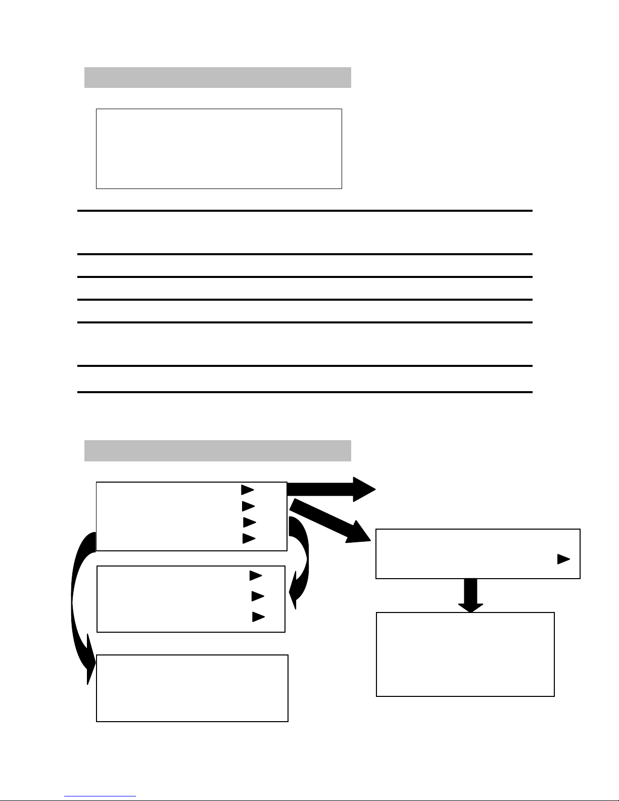
Customized EDID
DVI port #7
H 1920 V
Output refresh rate
apply ► reset ►
DVI port
Select the signal source port which needs customized
EDID.
H
Adjust the value of horizontal resolution.
V
Adjust the value of vertical resolution.
Output refresh rate
Adjust the value of refresh rate.
application
Write the adjusted resolution parameters into user
setting, apply the customized EDID.
Restore
Restore the default parameter settings.
Fuction
Language
Multi-Preview
User Templates
Factory Reset
Multi-Preview Off
Port Configuration
Input 1 VGA On
Input 2 VGA On
Input 3 VGA On
Input 4 VGA On
Saved Template
Loaded Template
Template Reset
Factory Reset
Press "OK" button to confirm
Press the "Back" key to return
Page 31

27
Language
You can choose the type of language customer needs.
"English" and "Chinese".
Multi-Preview
Simultaneously preview the specified or the entire channel
screen. Multi-channel pre-monitoring uses the
time-sharing processing technology. Therefore when
opening the multi-channel preview function, please select
the input channels which need to pre-monitored. Only
activated channels are pre-monitored.
User Template
"Save" or "Activate" template.
Saved Template Save the current parameter settings in
the specified template. Select the knob to save the
template serial number.
Loaded Template Loaded the template saved in
advance. Select the knob to choose the desired template
need to be loaded。
Template Reset Restore the factory settings of the
template.
Factory Reset
Restore factory settings.
Usually there will be different parameter settings when switching from one
image to another, so it needs to adjust corresponding parameter settings if
switch from two-image to three-image. There will not be enough time on site,
so the functions of templates will be important. Preparing the two-image data
into a template and three-image data into another, it only needs to switch
between the two templates to achieve multi-image switching.
Page 32
28
Port Introduction
MIG-630C series is supportive for 6 AV signal input, 6 VGA signal input and 4
DVI input,and 2 expanding input, including 1 SDI input and 1 DVI input.
MIG-630Cseries is supportive for 3 group signal output including main output,
preview 1 and preview 2. They are all independent output, and each group
includes 1 VGA and 1 DVI.
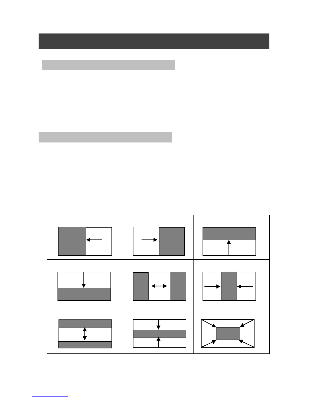
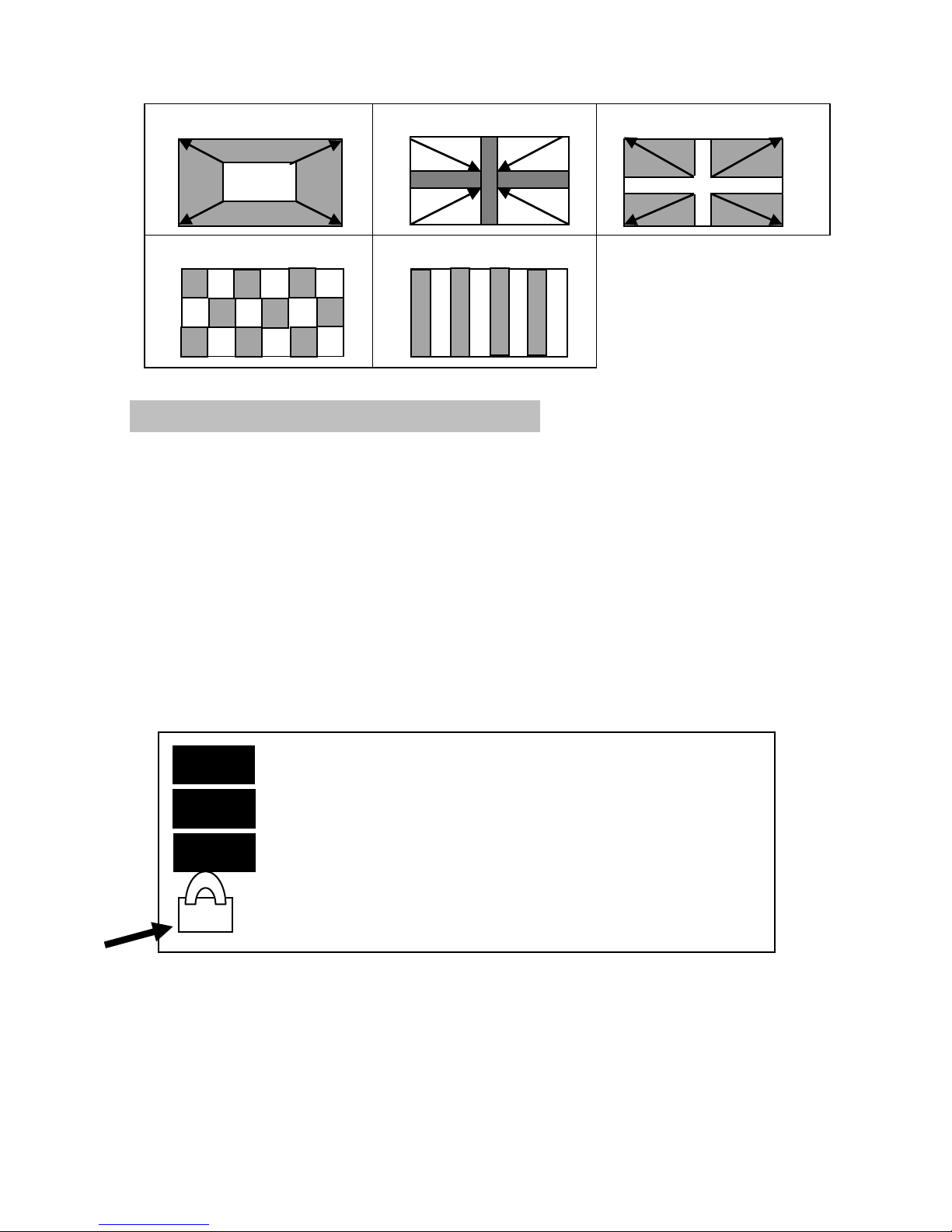
The 14 kinds of transition effects are shown as below:First choose input signal
which needs to present through PRE 1. When the signal is presented on the
screen steadily, switch the preview channel image and main channel image by
switch button. The switching mode can be exchanging or copying, and the
switching effect can be selected, like instant switch or fade in and fade out, or
wiping. The 14 types of switching effects are shown below:
Slide to the Left
Slide to the Right
Slide Up
Slide Down
Horizontal
Outwards
Horizontal Squeezing
Vertical Expanding
Vertical Squeezing
Squeezing
QUICK APPLICATION
Signal Switching
Page 33
29
Expanding
Cross-shape
Squeezing
Cross-shape Expanding
Checkerboard
Shutter
Shortcut Introduction
Number Key
There are three rows of number keys. The first row are signal choosing keys of
the main channel, and the second row is input signal choosing key of channel
DVI 1. The third row is input signal choosing key of DVI 2. These keys are
corresponding to signal paths of rear panel.
LOCK
Locking button,lightly press this key,and the menu panel turns out with a
lock image(as the arrow below shows). At this time, other keys on the panel
are invalid, avoiding incidents caused by neglect touch.
Prog
Pre1
Pre2
#1
#2
#7
VGA
VGA
DVI
1920x1080
1920x1080
No signal
Output distinguish ability: 1920x1080
60Hz
60Hz
T
Page 34
30
PIP1
Double image shortcuts, lightly press this key, and open the debug menu of
picture in picture 1 in DVI 1.
PIP2
Double image shortcuts, lightly press this key, and open the debug menu of
picture in picture in DVI 2.
MULTI PREVIEW
Multi image preview, lightly pressing this key, and preview the chosen input
signal in DVI 2 by time division.
SIZE
Shortcut for adjusting image size,lightly pressing this key, and the menu to
adjust the three image size will pop out.
Picture in Picture1
Open
Horizontal Width1024
Horizontal Location 768
Vertical Height 0
Vertical Location 0
Picture in Picture 2
Open
Horizontal Width 1024
Horizontal Location 768
Vertical Height 0
Vertical Location 0
Size
Prog
Pre1
Pre2
H 1024 V 768
H 1024 V 768
H 1024 V 768
Page 35
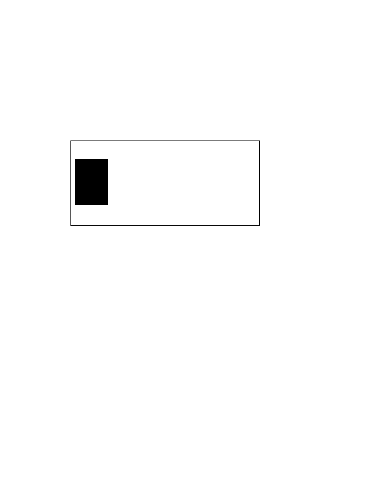
31
Prog represents the main channel. Pre1 represents preview channel 1. Pre2
represents preview channel 2. H represents horizontal width. V represents
vertical height.
POSITION
Shortcut for adjusting image location,lightly pressing this key, and the menu
to adjust the three image location will pop out.
Prog represents the main channel. Pre1 represents preview channel 1. Pre2
represents preview channel 2. H represents horizontal start. V represents
vertical start.
EFFECT1 和 EFFECT2
Effect switching button,define the switching effects of the two keys, and
lightly press the two keys, then switch effects can be chosen.
CUT
Instant switch button,lightly press this key and turn the switch effect into
instant switch.
FADE
Fade in and fade out button,lightly press this key and make the switch effect
fade in and fade out.
Position
Prog
Pre1
Pre2
H 0 V 0
H 0 V 0
H 0 V 0
Page 36
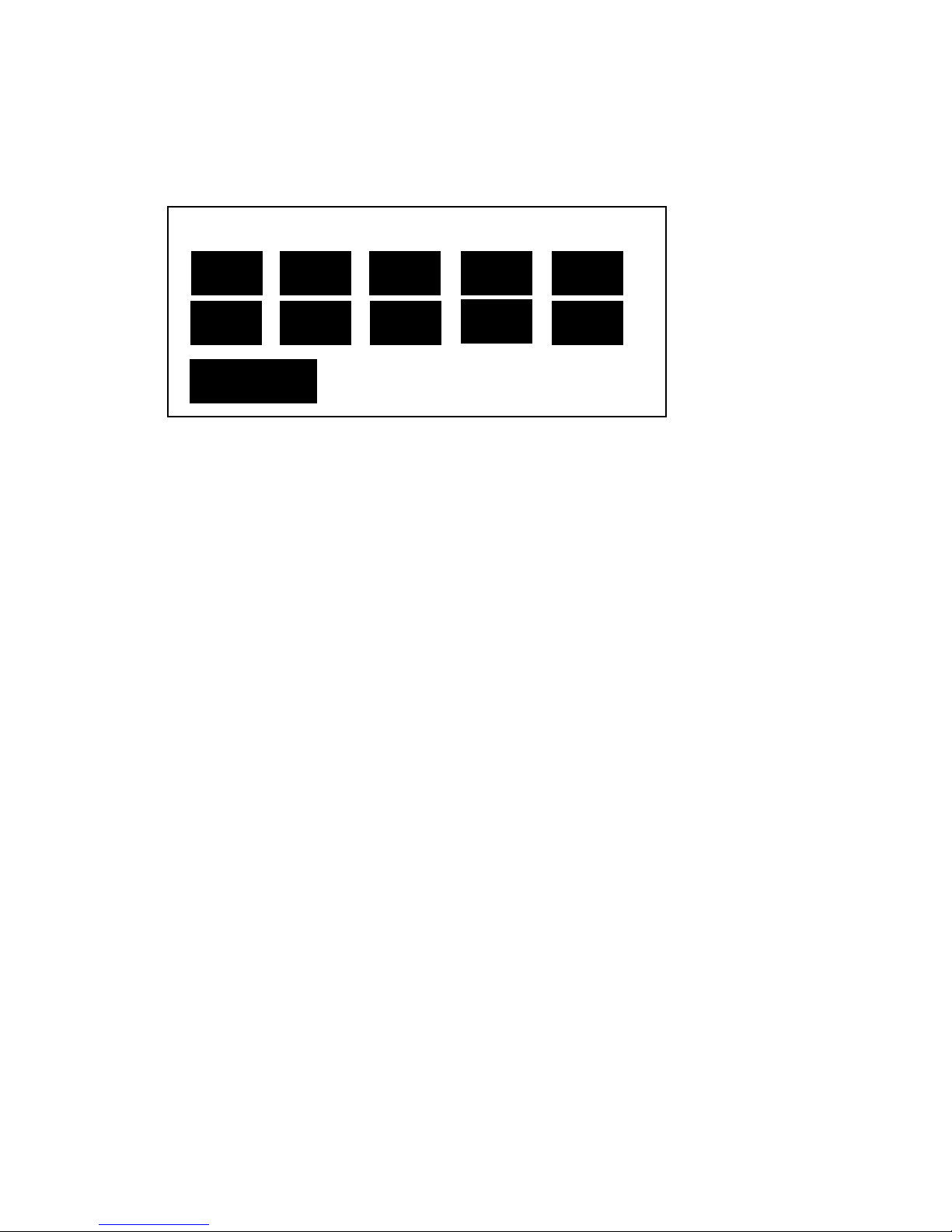
32
MODE
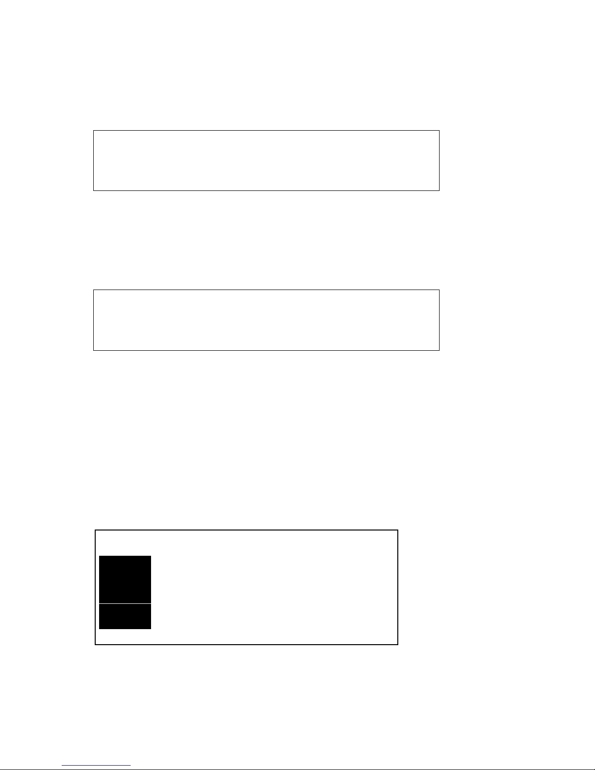
Mode shortcut button, lightly press this key and mode dialog box will pop out
as below
Number Key 1 to 10 can choose serial number of templates which are needed
for loading or reservation. Lightly pressing key “EFFECT1”, the current menu
can be switched into template loading interface. Lightly pressing key “EFFECT
2”, the current menu can be switched into template reserving interface.
FREEZE
Screen freeze button, the three output channels are equipped with one freeze
key each. Lightly pressing this key will stop the graphics.
LOGO
Shortcut button, lightly pressing this key, prepared LOGO can be added. This
shortcut only serves for main channel and DVI 1 channel.
BLACK
Black background shortcut button,lightly pressing this key will make the
channel turn a blank screen. This shortcut only serves for main channel and
DVI 1 channel.
TAKE
Switching button,lightly pressing this key executes switching.
OK
Confirmation button,lightly pressing this key to choose or perform certain
function.
Backspace button, lightly press this key and return to superior menu.
Preview 2 Number Key Loading Mode
1 2 3 4 5
6
7 8 9
10
: Load/Reserve
EFFECT1/2
Page 37
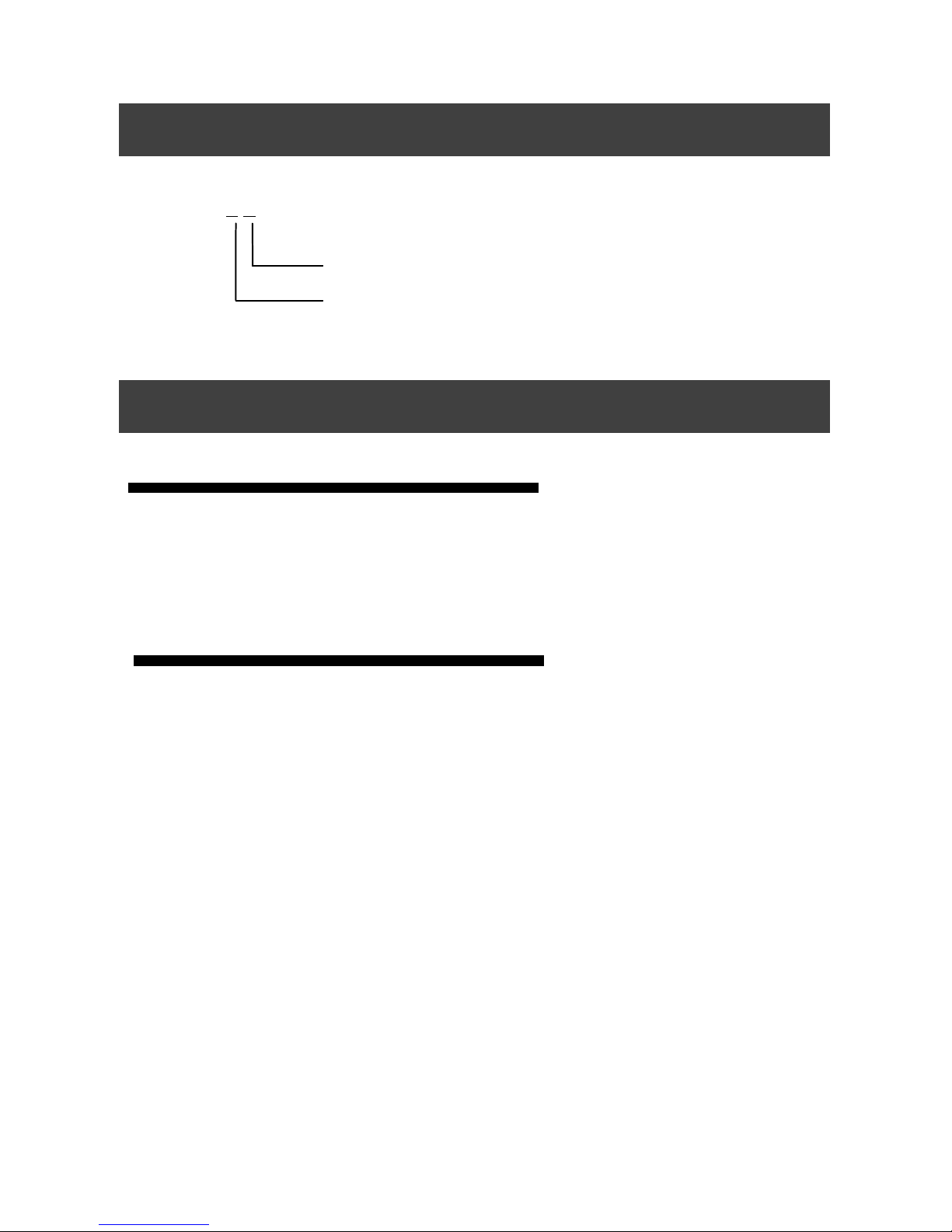
33
MIG-630C X X
Whole Unit Warranty Period
One year (from the buying date);
If the invoice is lost, the 60 days after the production date will be the
warranty start date for the product.
The warranty provisions
Immersion in water, collision, blots and scratch on surface after use, or
other failures and damages caused by abnormal use;
Disassembling and retrofit unauthorized by our company;
Failures and damages caused by abnormal working environment (like
over heated temperature, low or unsteady voltage);
Failures and damages caused by irresistible reasons (like fire hazard and
earthquake) or natural hazards (like lightening stroke) ;
Beyond warranty period.
Model Introduction
Warranty Explanation
Expand Input 1
Expand Input 2
 Loading...