

Mietzsch VRE 100/731, VRE 100/734, VRE 560/731, VRE 560/734, VRE 160/731 User Information
...
GmbH Lufttechnik Dresden
USER INFORMATION
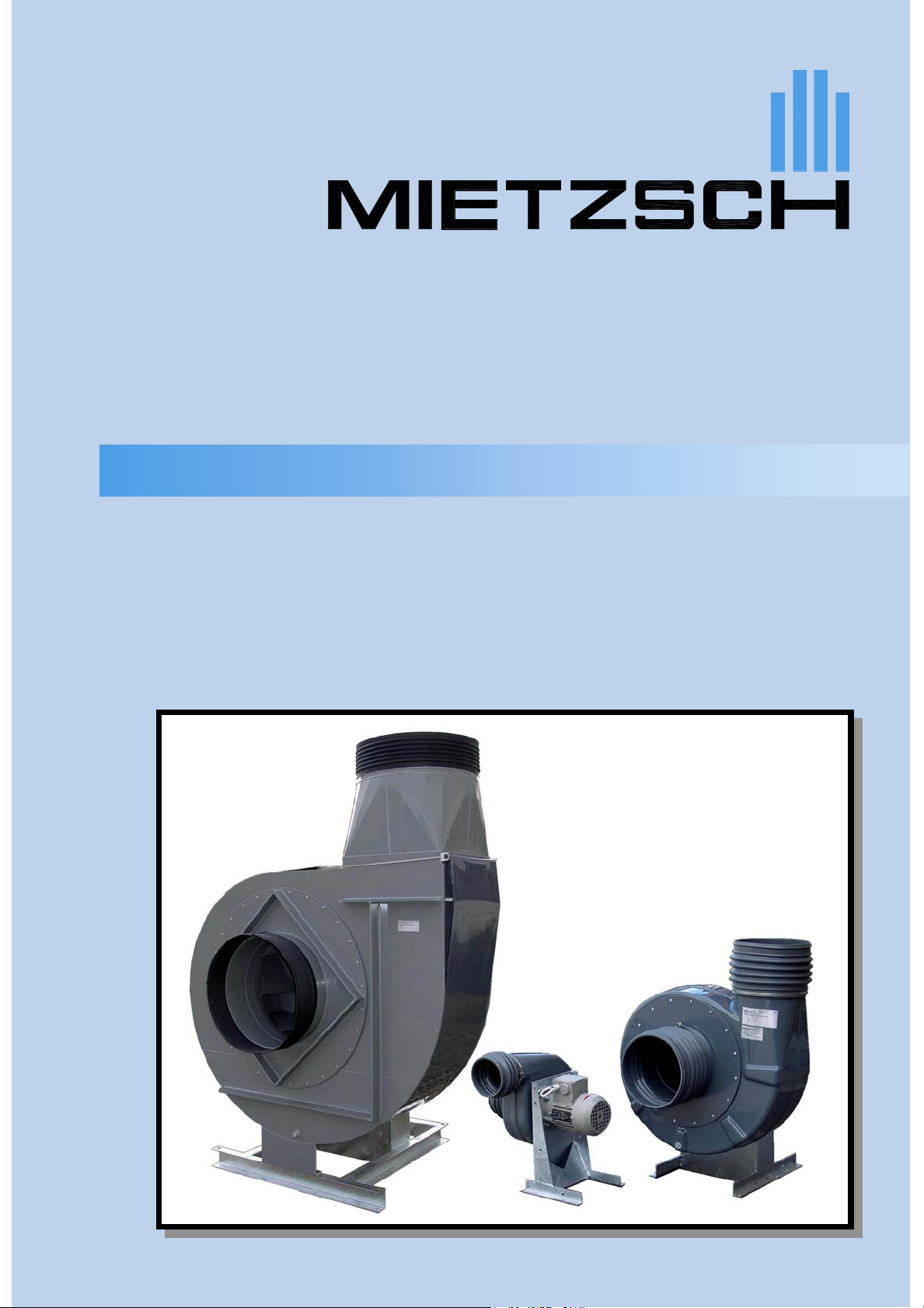
RADIAL FANS
RADIAL FANS
SERIES VRE 100 ... 560
direct driven
Issue 09/06
Radial fans of plastic materials
Series VRE VRE 100 ... 560
direct driven
Application in all ranges of ventilation
High chemical resistivity by the use of plastic materials
(PVC, PPs, PE, PVDF,GfK, electrically conductive plastic)
High efficiency and little noise emission
Volumetric flow up to 36 000 m3/h
Pressure increase up to 3 300 Pa
Capacity gradation by nine sizes and two versions
Housing positions left and right (L and R)
Explosion-proof versions according to European Directive 94/9/EG (ATEX)
Varied casing connectors
Many electrical and ventilation accessories
Data specified herein are subject to alteration without prior notice.
i_vre_en (09/06)
They will not be valid without written confirmation by the manufacturers.
Radial fans of plastic materials
Series VRE
direct driven
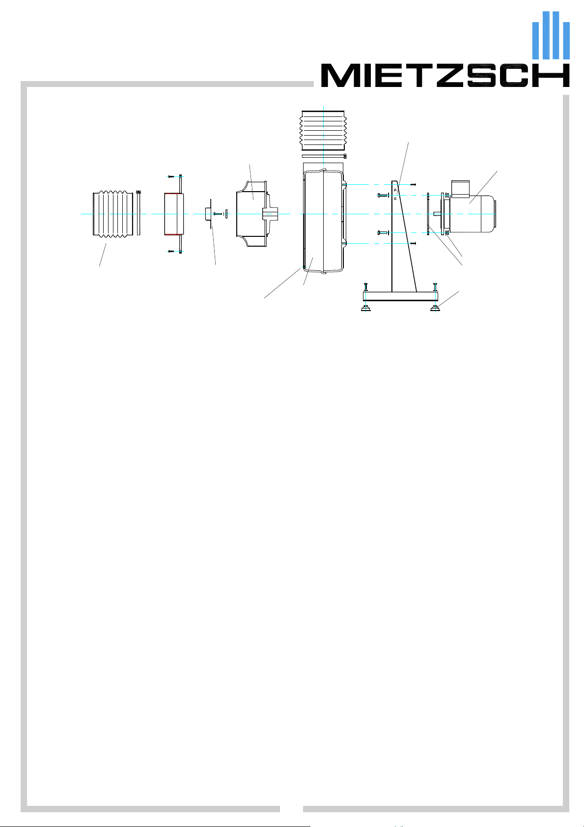
Technical explanation
base
intake socket
elastic connection
with tensioning tape
hub protection cap
impeller fastening
APPLICATION
High resistance to corrosion resulting from the use of high-quality plastic materials makes the radial fans of type VRE
suitable in particular for process exhausting devices in the chemical and pharmaceutical industries, for ventilating
laboratories, battery rooms, pickling and washing plants, galvanic and agricultural facilities etc.
impeller
casing
condensate drain
motor
motor fastening
adapter ring
vibration absorbers
TECHNICAL DESCRIPTION
Main components of the fans are the impeller, spiral casing, casing connections, base, and driving motor. The motor is
flange-connected directly to the base and completely separated from the flowing medium. The impeller has been arranged
on the motor shaft and is driven directly. Steel components - such as screws, hub and hub connections - are made of acidresistant steel or protected against corrosion by plastic coverings.
The aerodynamic design of the fans is state-of-the-art so that high efficiency, low sound levels, and high performance
density can be achieved.
Every fan is supplied as a complete assembly unit ready for use. Vibration absorbers matched in size and quantity, elastic
connections on the pressure and suction sides, and a condensate drain bore with closing cap are elements of the standard
range of delivery.
Design features
Impeller: There are two impeller designs covering a wide range of performance:
Type 731 with vanes curved backward
Type 734 with vanes curved forward
Special impellers are used for special applications. Impellers with vanes in radial arrangement, for instance,
are advantageous if the medium conveyed contains intensely sticking substances.
The impellers are made of single components and assembled with progressive joining methods. Dynamic
balancing complies with ISO 1940.
Materials: PVC, PPs, PVDF, FRP (for high demands), electrically conductive plastic material (explosion-proof fans)
Casing: The casings are made of deep-drawn half shells (sizes 100 … 250 made of PVC or PPs) or even side walls
and a jacket which are tightly welded. The connection diameter on the suction side is in any case identical with
the nominal size of the fan. The casing can be opened on the suction side for cleaning. A condensate drain has
been arranged in deepest position.
Sealness of the shaft lead-through that is sufficient for many applications results from the vanes with far end
arrangement. Higher demands on sealness are met by an additional seal between impeller and casing (see
section Shaft seal).
A shatter guard or an additional FRP reinforcement should be arranged for cases of high demands on safety.
A wide range of casing connections is available for connecting ventilation lines.
Note: Connected plant components must not load the fan mechanically.
Materials: PVC, PPs, PVDF, FRP (for high demands), electrically conductive plastic material (explosion-proof fans)
Base: Robust welded design of zinc-coated sheet steel, optionally available: varnished or of stainless steel.
Motors: Standard motor: 3 ~ 400 V/ 50 Hz, degree of protection IP 54, design B 5 (in special cases B 14 or B 3)
Single-phase motors 230 V/ 50 Hz, motors with special voltages and different degree of protection, polechanging and explosion-proof motors
Motors with thermal winding protection (PTC resistor) --> special design TS
Motors with integrated frequency inverter --> special design MFU
i_vre_en (09/06)
MIETZSCH GmbH Lufttechnik Dresden Großenhainer Str. 137 01129 Dresden Fax (0351) 8 58 00 74 http://www.mietzsch.de
03
Radial fans of plastic materials
Series VRE
direct driven
Technical explanation
CONDITIONS OF USE
permissible ambient temperature: -30 °C … 40 °C (EX motors -20 °C ... 40 °C)
permissible temperature of medium conveyed: -30 °C … 40 °C
Higher temperatures depend on the design size, material, and speed rate and are subject to consultation with the
manufacturers.
The applied materials have good chemical resistance against many substances. It should be considered, however, that
evens plastic materials are attacked by certain chemicals. This depends on the following items:
Chemical composition and concentration of medium conveyed
Temperature and time of action
Mechanical loading and residual stress resulting from processing
Many applications in fields such as laboratories and stockrooms for chemicals, in agriculture and damp-loaded processes
led to good results with "standard materials" such as PVC or PPs that can be used without any problem in most cases.
Critical applications may occur in the process-technological industry - surface refinement, pickling plants, process exhaust
air in microelectronics.
For selection of suitable materials the purpose of use of the fan and the type of medium conveyed should be
specified in requests or orders.
Slightly dust-laden media can also be conveyed but lead to increased wear.
Notes on outdoor use: If possible, fans should not be exposed to intense ultraviolet radiation.
The motor should be protected by a weather hood.
Ambient conditions have to be considered in material selection.
Working range: The fans show stable operation in the entire range of the characteristic shown. Operation with smaller
volume flows is possible but very ineffective. Use with larger volume flows may lead to motor overload
(type 734 in particular) and must be avoided.
Parallel arrangement: of type 731 is possible in any case, of type 734 after consultation with the
manufacturers only.
Series arrangement: requires the manufacturers' agreement (increased casing pressures).
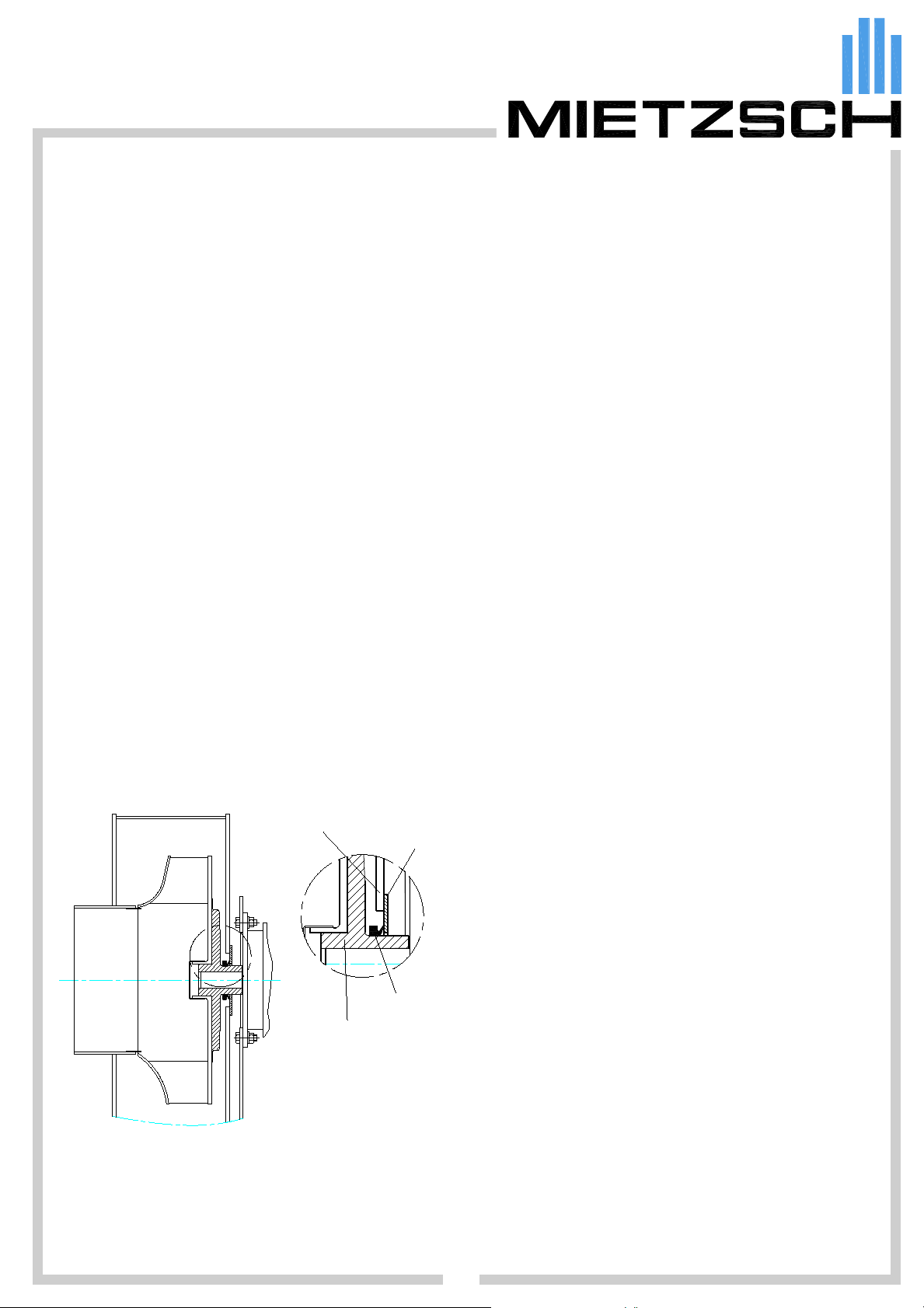
SHAFT SEAL
Radial fans VRE with standard design have vanes in far end arrangement and formed on the rear hub protection cap. This
means permanent intake of external air through the minimized gap of the shaft lead-through if
pressure loss on suction end is greater that one third of total pressure loss.
This is the reason why components with high pressure losses such as washers, filters, separators etc. should be arranged,
whenever possible, before the fan, i.e. on the suction side.
casing wall
counter-runway
sealing ring
impeller hub
A shaft seal is used if this "aerodynamic casing sealing" is
not sufficient. This may happen if, for instance, there is the
risk of aggressive gas escaping with the fan at rest.
The hub body of special design GD carries a sealing ring
with axially acting flexible sealing lip.
The counter-runway in the casing wall consists of a material
with good sliding properties (stainless steel or a special
plastic material, the latter in cases of action of hydrochloric
acid, chromic aid, hydrofluoric acid etc.).
This seal is used for high demands on gastightness and in
cases of relatively dry outlet air. It is distinguished by its long
service life.
There are various special seals such as gas shutoff seals,
labyrinth seals etc. for very high demands on tightness, in
particular in cases of high humidity and much condensate.
The manufacturers should be contacted for such
applications.
SPECIAL DESIGNS and ACCESSORIES (more details at the end of this brochure)
Cleaning opening, shatter guard, weather hood for motor, various connections for condensate drain, base of stainless
steel, intake and outlet protective grating
Ventilation components: ducts, elbows, flaps, air hoods, pipe and profiled silencers
Electrical accessories: repair switches, motor protection switches, pole changing switches, complete fan controls,
i_vre_en (09/06)
MIETZSCH GmbH Lufttechnik Dresden Großenhainer Str. 137 01129 Dresden Fax (0351) 8 58 00 74 http://www.mietzsch.de
frequency inverters (also with pressure and volumetric flow regulation), air flow monitoring.
04
Radial fans of plastic materials
Series VRE
direct driven
Technical explanation
EXPLOSION PROTECTION
Guideline 94/9/EG (ATEX) newly regulates explosion protection for non-electrical devices from July 1, 2003. In addition to
observation of design and safety instructions according to DIN EN 14986 and DIN EN 13463, the fan has to be assigned
exactly to the relevant degree of protection and labelled accordingly. The manufacturers have to prove conformity.
Areas with hazard of explosion exist in the chemical industry, in gasworks, coking plants, varnishing units, petrol stations,
sewage and wastewater treatment plants, laboratory systems etc.
Prerequisites of explosion are:
Flammable substances (such as gas, dust),
Oxygen in sufficient quantity of air
Ignition source (sparks, fire, hot surfaces, electrostatic discharges)
The following measures have to be taken if explosions cannot be excluded:
Prevention of explosible atmosphere
Avoidance of ignition sources
Moderation of damaging effects of explosions
An efficient and supervised ventilation system is often a sufficient measure for avoiding ignitable atmosphere and,
consequently, hazard of explosion.
Protection demands on a fan depend on the probability of occurrence of explosible atmosphere in the medium conveyed
or/and in the surrounding. Hazard is classified in three zones:
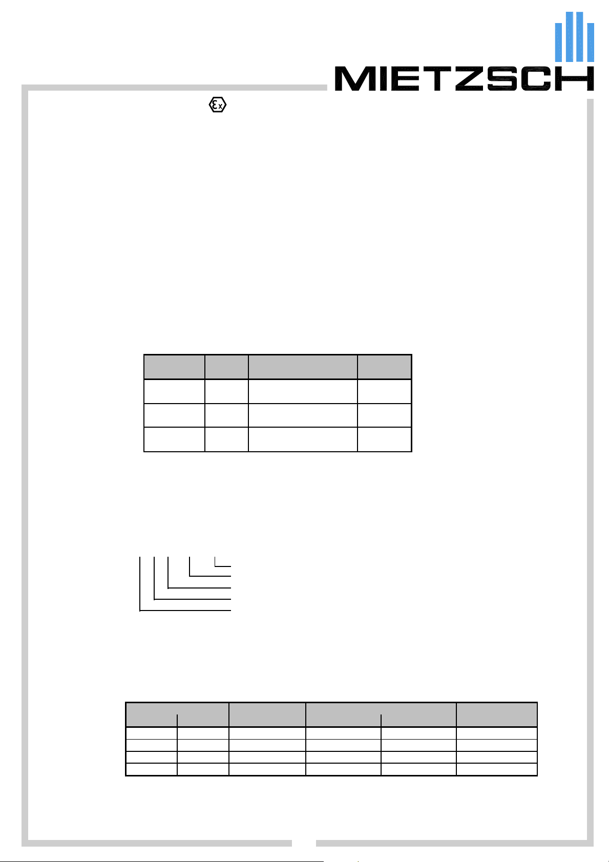
Explosions Hazard Avoidance of Category
hazard zone ignition sources acc. to ATEX
continuous zone 0 even in the event of 1
long periods rare incidents
likely zone 1 even in the event of 2
to occur frequent disturbances/faults
infrequently zone 2 during norm al operation 3
short period
The plant operator or the relevant board of control has to decide which protection is necessary and which additional
regulations have to be considered. This means that the customer has to specify in the order which kind of protection the fan
has to have.
Fans VRE are supplied for the following types of ignition protection:
Zone 1: II 2G c IIB+H2 T3
Zone 2: II 3G c IIB+H2 T3
temperature class T3 (ignition temperature of gas > 200 °C)
explosion group of gases IIB+H2 (IIA and H
constructional safety
category (2G = gases of zone 1, 3G = gases of zone 2)
Equipment-group II (use in mining not permissible)
On principle, application in zone 0 is not possible. Gases of explosion group IIC (hydrogen excluded), gases with ignition
temperature below 200 °C, and combustible dusts are likewise impermissible.
included, IIC not included)
2
Classification generally differentiates between inside (medium conveyed) and outside (surrounding). Every zone of hazard
requires its special design. Explosion-proof electrical devices (motors, switches etc.) and electrically conductive materials
(preferably conductive and flame retardant polypropylene --> PPsX) are employed. General classification is as follows:
Ha za r d zon e
inside outside
zone 2 zone 2
zone 2 none
zone 1 zone 1 Z1Z1 EEx e II EEx de conductive
zone 1 zone 2 Z1Z2 EEx e II EEx de conductive
Special demands for operation with frequency inverter
Motors with increased safety EEx e II must not be used in inverter operation. Motors EEx de with flameproof enclosure can
be employed in inverter mode if they are equipped with special winding protection (special design TS15). Standard motors
can be used and operated in inverter mode if the surrounding is not an EX zone and the fan meets certain design demands.
i_vre_en (09/06)
MIETZSCH GmbH Lufttechnik Dresden Großenhainer Str. 137 01129 Dresden Fax (0351) 8 58 00 74 http://www.mietzsch.de
MIETZSCH Impeller/ housing
designation without inverter with inverter material
Z2Z2 EEx e II EEx de not conductive
Z2Z3 EEx e II standard not conductive
05
Motor

Radial fans of plastic materials
Series VRE
direct driven
Technical explanation
EXPLANATION OF TYPE DESIGNATIONS
VRE 250 / 731 W 1450 - TS - GD - 090 L - PE/PPs
Fan (radial, one suction side)
Nominal size (inlet diameter /mm)
Impeller type
731 - curved backward
734 - curved forward
(special disigns of impeller types)
Direct drive
Nominal speed rpm
(higher speed in cases of pole-changing motors)
Brief designation of special versions
E = single-phase drive
TS = with thermal winding protection (thermistor)
P1 = pole-changing motors with speed halving (Dahlander)
such as 1450 P1 = 1450/710 rpm
P2 = pole-changing motors with Separate windings
such as 1450 P2 = 1450/950 U/min (changeover to next smaller speed)
EX = with motor increased safety EEx e II T3
EXde = with motor flameproof enclosure EEx de IIC T4
ZiZo = explosion-proof fan for zone i=inside and o=outside
such as Z1Z2 = inside zone 1 and outside zone 2
GD = gastight (with shaft sealing)
GDS = high gastight casing for humid media with condensate
DD = motor in delta connection for frequency inverter 3x230V
(in case of mounted repair switch)
Housing positions (view from intake side)
Material (casing/impeller)
PERFORMANCE PARAMETERS
All performance parameters are determined on MIETZSCH-own test racks. The design corresponds to DIN 24 163. The
volumetric flow is determined from the differential pressure by means of a measuring nozzle according to EN ISO 5167 .
In cases of radial fans that are destined to be arranged within a plant, the total pressure difference ∆p
∆p
= p
t
t D
- p
t S
= ( p
stat D
+ ρ/2 * c
2
) -
D
( p
stat S
+ ρ/2 * c
2
)
S
This size corresponds to the usable total pressure losses on the suction side (S) and the pressure side (D).
If area of inlet and outlet are equal total pressure difference is identically to static pressure difference
∆p
= p
t
statD
-
p
statS
= ∆p
stat
In praxis a pressure difference diminished by the dynamic pressure is often used. This size corresponds to the pressure
difference for free blowout ∆p
= ∆pt - ρ/2 * c
∆p
fa
Duct sound power level L
which is used for roof fans:
fa
2
D
WA
(to designate it static pressure difference is incorrect)
The measuring method for determination of the duct sound power level is specified in DIN 45 635, Part 9. Interpretation is
according to
= L
L
WA
value measuredt
Sound pressure level L
3m
+ 10 * log ( π / 4 * D2 ) dB D = diameter of measuring line
Several measuring points are arranged on an enveloping surface around the fan. Conversion to the specified level at 3
meters is calculated from
results from
t
L
= L
3m
value measuredt
i_vre_en (09/06)
+ 20 * log ( rm / 3m ) dB
06
MIETZSCH GmbH Lufttechnik Dresden Großenhainer Str. 137 01129 Dresden Fax (0351) 8 58 00 74 http://www.mietzsch.de
Radial fans of plastic materials
Series VRE
direct driven
Technical explanation
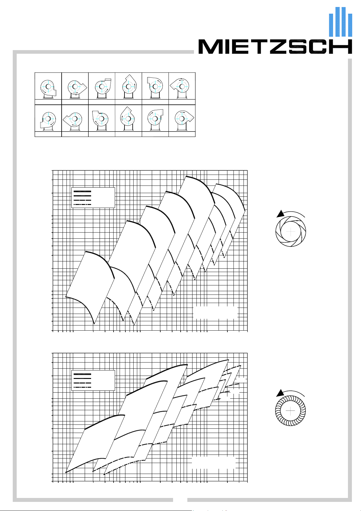
HOUSING POSITIONS (view from inlet side)
0L
0R 45R
SURVEY OF TYPES - PRESELECTION
4000
3000
2000
1000
∆p / Pa
t
500
400
300
45L 90L
90R
2900 U/min
1450 U/min
950 U/min
710 U/min
135L
135R
180L
180R
0
6
1
All fans are available in direction of rotation L (left)
und R (right) and in 6 different housing positions.
225L
Changing the position of the casing after
manufacturing is complicated. Please consult the
manufacturer.
225R
VRE 731
impeller with backward
5
1
3
0
5
2
0
0
2
0
5
4
0
0
4
0
6
5
0
0
5
curved vanes
direction of rotation left
200
0
0
1
ß
ö
r
g
n
n
e
N
2900 U/min
1450 U/min
950 U/min
710 U/min
e
Bezugsdichte des Fördermediums
ρ = 1,2 kg/m³
.
V / m³/h
0
0
0
0
2
5
0
6
1
2
0
0
1
e
ß
ö
r
g
n
n
e
N
1
3
0
5
Bezugsdichte des Fördermediums
4
560
500
450
ρ = 1,2 kg/m³
VRE 734
impeller with forward
curved vanes
direction of rotation left
.
V / m³/h
i_vre_en (09/06)
4000
3000
2000
1000
∆p / Pa
t
100
50
30
10050 2000200 300 1000500 1000050003000 20000 30000
500
400
300
200
100
80
10050 2000200 300 1000500 1000050003000 3000020000
07
MIETZSCH GmbH Lufttechnik Dresden Großenhainer Str. 137 01129 Dresden Fax (0351) 8 58 00 74 http://www.mietzsch.de
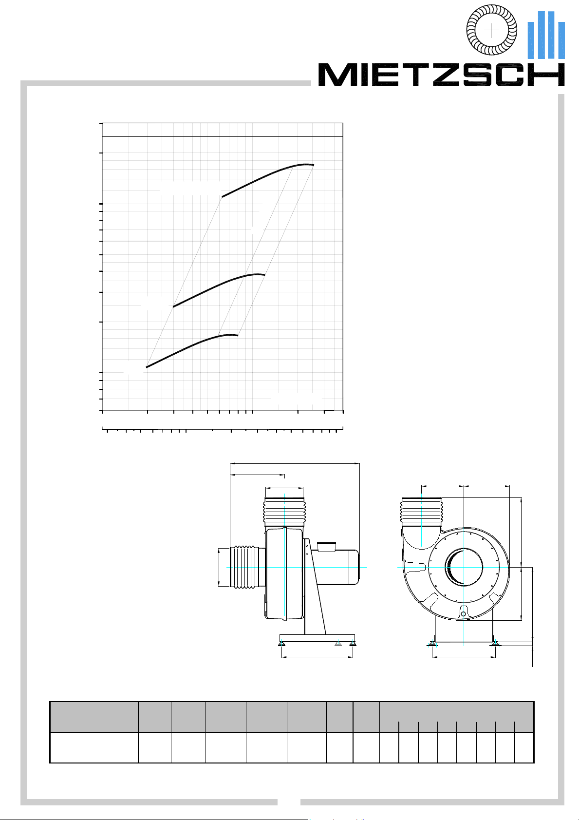
Radial fans of plastic material
r
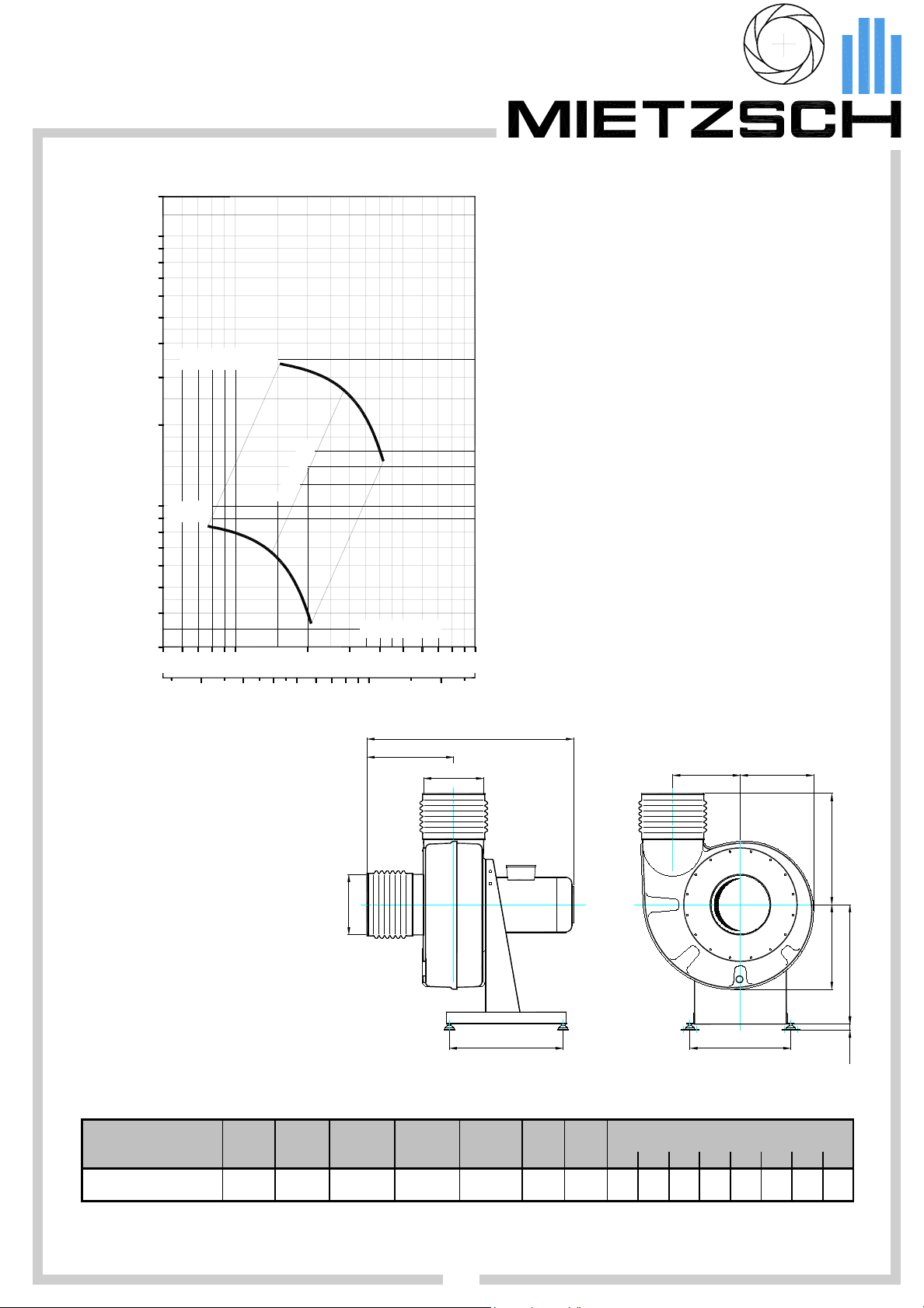
VRE 100 / 731
Impeller with backward curved vanes
PERFORMANCE
1400
Working range
∆p / Pa
t
1000
500
400
300
200
100
50
30
2900 U/min
1450
50
0,02
100
0,03
=
a
m
η
200
0,05
- stable regime in entire characteristic
range
- fan can be operated beyond
characteristic specified
- parallel connection possible, series
connection after consultation with the
manufacturers
Design features
- welded impeller with 8 vanes curved
5
7
,
0
x
ρ = 1,2 kg/m³
300
0,1
500400
0,2
1000
.
V / m³/h
.
V / m³/s
backward
-casing
deep-drawn for PVC or PPs
welded for special materials
- motor outside the flow conveyed
- robust sheet metal base, zinc-coated
- vibration absorbers in range of
delivery
- variant connectors of casing
PRINCIPAL DIMENSIONS
(made of PVC or PPs )
The principal dimensions refer to elastic
connectors on inlet and outlet and for
housing position 90R.
Height of axis is identical for all housing
positions.
Further dimensions see page 26.
For special materials see page 28.
Number of
Drawings in format dxf
vibration absorbers : 4
--> MIETZSCH-CD
Ø 110
165
Ø 110
max.570
198
119
120
205
144
204
MOTOR VERSIONS for standard motor 3~400V/50Hz
(Data for other motors, such as single-phase, polechanging or Ex, upon inquiry.)
fan type speed required powe
rpm kW kW A kg dB(A) dB(A) 63 125 250 500 1000 2000 4000 8000
VRE 100/ 731W1450 1450 0,0045 0, 12 0,42 9,5 45 62 39 43 58 54 54 55 44 37
VRE 100/ 731W2900 2900 0,035 0,18 0,51 10 51 68 52 60 62 63 61 55 46 36
power nom. motor nom. motor weight
current with motorL
L
L
A3mLWA
= A - weighted sound pressure level at distance of 3 m
A3m
= A - weighted sound power level in duct
WA
octave-band L
WA-Okt
/ dB(A)
240
20
i_vre_en (09/06)
08
MIETZSCH GmbH Lufttechnik Dresden Großenhainer Str. 137 01129 Dresden Fax (0351) 8 58 00 74 http://www.mietzsch.de

Radial fans of plastic material
r
VRE 100 / 734
Impeller with forward curved vanes
PERFORMANCE
1400
Working range
∆p / Pa
t
1000
500
400
300
200
100
2900 U/min
1450 U/min
50
30
50 200
0,02
100
0,03
0,05
7
6
,
0
=
x
a
m
η
ρ = 1,2 kg/m³
400 500
300
0,1
0,2
1000
.
V / m³/h
.
V / m³/s
- stable regime in entire characteristic
range
- operation with larger volumetric flows
may lead to motor
- parallel and series connection
possible after consultation with the
manufacturers
Design features
- welded impeller with 32 vanes curved
forward
-casing
deep-drawn for PVC or PPs
welded for special materials
- motor outside the flow conveyed
- robust sheet metal base, zinc-coated
- vibration absorbers in range of
delivery
- variant connectors of casing
PRINCIPAL DIMENSIONS
(made of PVC or PPs )
The principal dimensions refer to elastic
connectors on inlet and outlet and for
housing position 90R.
Height of axis is identical for all housing
positions.
Further dimensions see page 26.
For special materials see page 28.
Number of
Drawings in format dxf
MOTOR VERSIONS
vibration absorbers : 4
--> MIETZSCH-CD
for standard motor 3~400V/50Hz
Ø 110
165
Ø 110
max.570
198
119
120
205
144
204
(Data for other motors, such as single-phase, polechanging or Ex, upon inquiry.)
fan type speed required powe
rpm kW kW A k g dB(A) dB(A) 63 125 250 500 1000 2000 4000 8000
VRE 100/ 734W1450 1450 0,024 0,12 0,42 10 45 61 42 56 56 53 56 47 39 23
VRE 100/ 734W2900 2900 0,17 0,18 0, 51 10 54 72 57 65 67 63 67 64 51 42
power nom. mot or nom. mot or weight
current with motorL
L
L
A3mLWA
= A - weighted sound pressure level at distance of 3 m
A3m
= A - weighted sound power level in duct
WA
octave-band L
WA-Okt
/ dB(A)
240
20
i_vre_en (09/06)
09
MIETZSCH GmbH Lufttechnik Dresden Großenhainer Str. 137 01129 Dresden Fax (0351) 8 58 00 74 http://www.mietzsch.de
Radial fans of plastic material
r
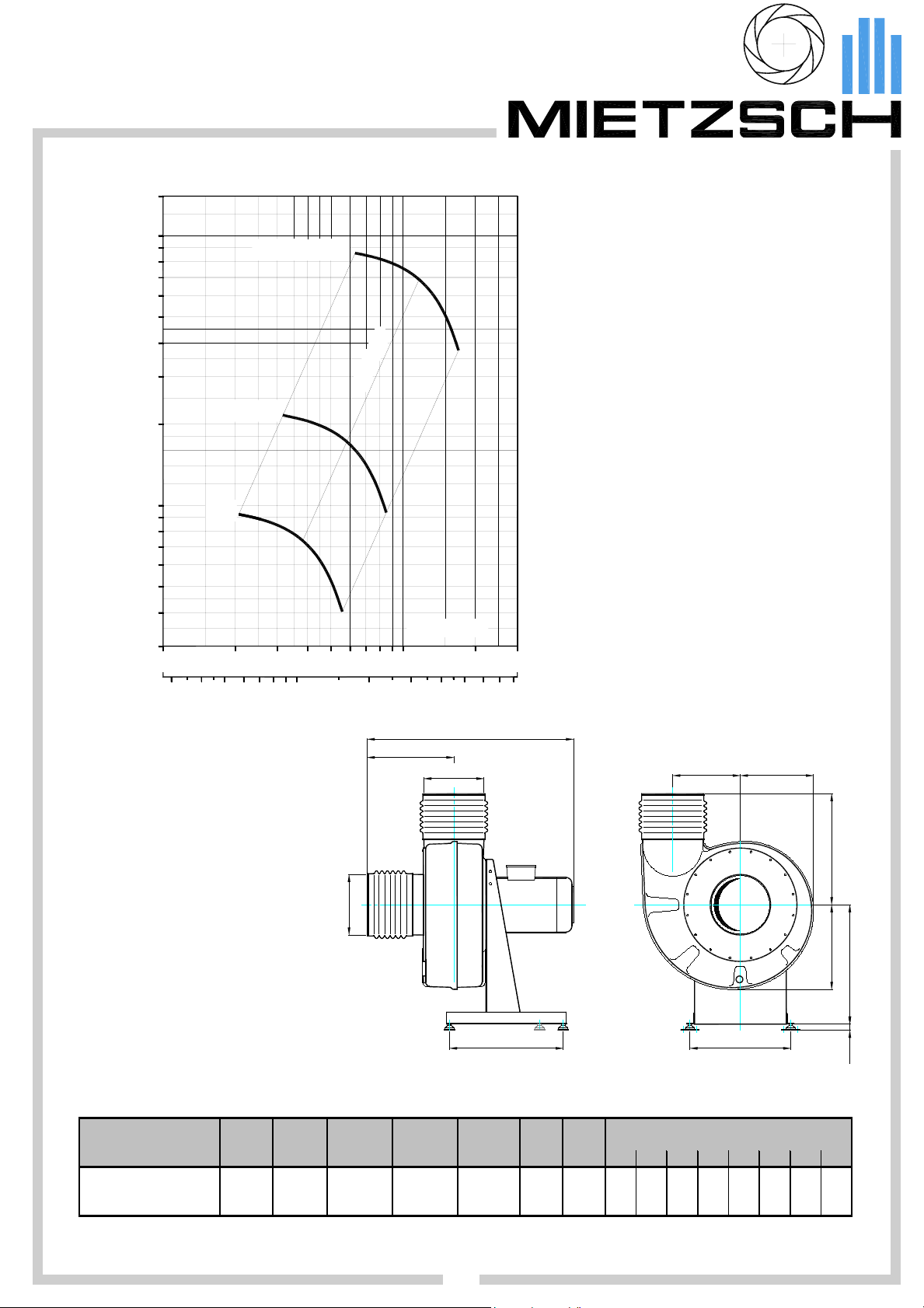
VRE 160 / 731
Impeller with backward curved vanes
PERFORMANCE
1400
Working range
∆p / Pa
t
1000
500
400
300
200
100
50
30
100
950
0,050,03
2900 U/min
1450
300
200
8
7
,
0
=
x
a
m
η
ρ = 1,2 kg/m³
400 500 2000
0,1 0,30,2 0,50,4
30001000
0,8
.
V / m³/h
.
V / m³/s
- stable regime in entire characteristic
range
- fan can be operated beyond
characteristic specified
- parallel connection possible, series
connection after consultation with the
manufacturers
Design features
- welded impeller with 8 vanes curved
backward
-casing
deep-drawn for PVC or PPs
welded for special materials
- motor outside the flow conveyed
- robust sheet metal base, zinc-coated
- vibration absorbers in range of
delivery
- variant connectors of casing
PRINCIPAL DIMENSIONS
(made of PVC or PPs )
The principal dimensions refer to elastic
connectors on inlet and outlet and for
housing position 90R.
Height of axis is identical for all housing
positions.
Further dimensions see page 26.
For special materials see page 28.
Number of
(in case of heavy motors 6)
Drawings in format dxf
vibration absorbers : 4
--> MIETZSCH-CD
Ø 160
266
max.810
Ø 160
310
192179
315
222
274
20 332
MOTOR VERSIONS for standard motor 3~400V/50Hz
(Data for other motors, such as single-phase, polechanging or Ex, upon inquiry.)
fan type speed required powe
rpm kW kW A k g dB(A) dB(A) 63 125 250 500 1000 2000 4000 8000
VRE 160/ 731W950 950 0,014 0,09 0,44 17 39 56 39 51 46 48 50 48 33 16
VRE 160/ 731W1450 1450 0,045 0,12 0,42 17 44 62 44 57 53 55 56 53 43 26
VRE 160/ 731W2900 2900 0,31 0,37 1, 0 19 60 78 57 66 68 77 70 62 59 50
i_vre_en (09/06)
MIETZSCH GmbH Lufttechnik Dresden Großenhainer Str. 137 01129 Dresden Fax (0351) 8 58 00 74 http://www.mietzsch.de
power nom. motor nom. motor weight
current with motorL
10
L
L
A3mLWA
= A - weighted sound pressure level at distance of 3 m
A3m
= A - weighted sound power level in duct
WA
octave-band L
WA-Okt
/ dB(A)
V
V
Radial fans of plastic material
r
VRE 160 / 734
Impeller with forward curved vanes
PERFORMANCE
3000
Working range
∆p / Pa
t
2000
1000
500
400
300
200
100
60
100
0,03
950
0,05
2900 U/min
1450
200
0,1
- stable regime in entire characteristic
range
- operation with larger volumetric flows
may lead to motor
9
6
,
0
=
x
a
m
η
- parallel and series connection
possible after consultation with the
manufacturers
Design features
- welded impeller with 35 vanes curved
forward
-casing
deep-drawn for PVC or PPs
welded for special materials
- motor outside the flow conveyed
- robust sheet metal base, zinc-coated
- vibration absorbers in range of
delivery
ρ = 1,2 kg/m³
400300
500
0,2
1000
0,3
2000
0,5
3000
1,00,4
.
/ m³/h
.
/ m³/s
- variant connectors of casing
PRINCIPAL DIMENSIONS
(made of PVC or PPs )
The principal dimensions refer to elastic
connectors on inlet and outlet and for
housing position 90R.
Height of axis is identical for all housing
positions.
Further dimensions see page 26.
For special materials see page 28.
Number of
(in case of heavy motors 6)
Drawings in format dxf
MOTOR VERSIONS
vibration absorbers : 4
--> MIETZSCH-CD
for standard motor 3~400V/50Hz
Ø 160
266
max.810
Ø 160
310
192179
274
(Data for other motors, such as single-phase, polechanging or Ex, upon inquiry.)
fan type speed required powe
rpm kW kW A kg dB(A) dB(A) 63 125 250 500 1000 2000 4000 8000
VRE 160/ 734W950 950 0, 08 0,09 0,44 18 44 62 43 51 51 59 55 51 40 26
VRE 160/ 734W1450 1450 0,25 0,25 0,76 19 52 69 54 59 58 64 66 57 50 38
VRE 160/ 734W2900 2900 2,2 2,2 4,6 29 63 82 59 72 72 76 78 76 70 62
i_vre_en (09/06)
power nom. motor nom. motor weight
current with motorL
L
L
A3mLWA
= A - weighted sound pressure level at distance of 3 m
A3m
= A - weighted sound power level in duct
WA
octave-band L
WA-Okt
/ dB(A)
11
MIETZSCH GmbH Lufttechnik Dresden Großenhainer Str. 137 01129 Dresden Fax (0351) 8 58 00 74 http://www.mietzsch.de
315
222
20 332
 Loading...