

Mietav-tec FMT24-SUPER-2S-FP-PROG Owner's Manual
Installation
The FMT24-SUPER-2S-FP-PROG is designed for flush mounting in the room
to be controlled. It should be located where the occupant can easily read the
LCD display and use the controls. If the built in temperature sensor is being
used to measure room temperature, the module should be placed in such
location which represents the room general conditions. Cold or warm air
draughts; radiant heat and direct sunlight should be avoided.
Tel: (856) 2882882
Tel: +972-3-9626462
Fax: +972-3-9626620
support@meitavtec.com
FMT24-SUPER-2S-FP-PROG-F
Owner’s manual & Technician Settings
General points to follow:
- Disconnect power to the main board before installing the unit.
- The unit MUST be fitted into a standard electrical box (Carlon – B114R or similar)
- The unit should not be installed on an outside wall or where there is an air draft.
- The unit must not be exposed to a direct sunlight.
- The standard height to install this unit is 1.5 meter (5 feet) from the floor.
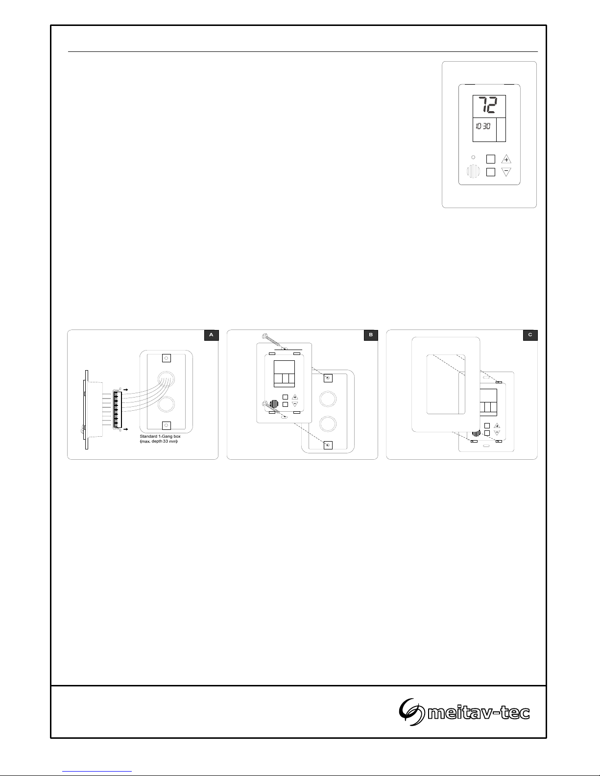
Installation procedure:
A. Connect the wires as shown in the wiring diagram section of this manual.
All terminals accept 1x0.5 mm
2
/24 AWG.
B. Place the thermostat in the electrical box and tighten up the 2 screws.
C. Adapt the front frame-panel into its place, by pushing it towards the wall.
ON
SELECT
ºF
ON
A.Speed
Cool
Heat
Su
AM
Program:Wake
Wiring
Before connecting or disconnecting any wires, ensure that all power supplies have been switched off and all
wires are potential-free to prevent equipment damage and avoid electrical shock.
All wiring to the thermostat is low (safe) voltage and must be separated from power line voltage wiring.
Do not run wiring close to transformers or high frequency generating equipment. Complete and verify all
wiring connections before applying power to the controller to which the module is connected.
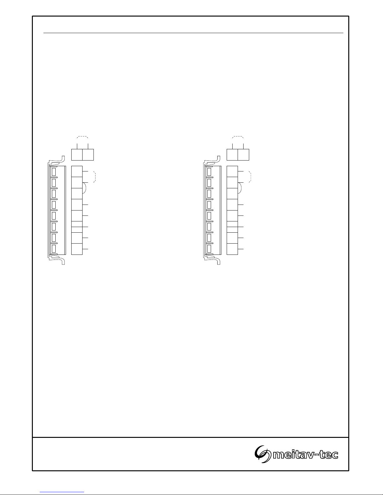
C
RC
RH
G1
W2
W1
G3
Y1
B/O
Tel: (856) 2882882
Tel: +972-3-9626462
Fax: +972-3-9626620
support@meitavtec.com
FMT24-SUPER-2S-FP-PROG-F
Owner’s manual & Technician Settings
**Main supply 24VAC
Notes:
1. For a heat pump system with no heat elements, leave terminals “W2” free.
2. For a non heat pump system with one heat element, leave terminals “W2” free.
3. RC-RH, - When using one transformer, RC,RH terminals must be shorted.
**Main supply 24VAC
System without heat pump
(heat elements only)
System with heat pump
External sensor
(option)
C
RC
RH
G1
W2
W1
G3
Y1
B/O
Fan low (0.5A)
Compressor (0.5A)
Heat element 1 (0.5A)
Fan high (0.5A)
Heat element 2 (0.5A)
Fan low (0.5A)
Compressor (0.5A)
Heat pump (0.5A)
Fan high (0.5A)
Heat element (2
nd
stage) (0.5A)
T T
External sensor
(option)
T T

External sensor Connection (option)
Res. KΩ 115.8 100.9 88.1 77.1 67.7 59.6 52.5 46.4 41.2 36.6
Temp °F 45 50 55 60 65 70 75 80 85 90
N.T.C Sensor: Temperature ~ Resistance characteristics
Connecting the external sensor
Disconnect power to the thermostat.
Move switches 1 and 5 to ON position and switch 6 to OFF position.
Connect the temperature sensor to the T-T terminals.
Reconnect power to the thermostat.
Notes:
The external sensor must be Meitav-tec type only!
The wire length for the external sensor can be up to 100 feet (30 meters) with standard cable.
If the distance is greater than 100 feet the wire MUST be shielded.
Tel: (856) 2882882
Tel: +972-3-9626462
Fax: +972-3-9626620
support@meitavtec.com
FMT24-SUPER-2S-FP-PROG-F
Owner’s manual & Technician Settings
DIP switch settings
Internal/External sensor
Use DIP Switches S1, S5 and S6 to select Internal/External sensor
Internal sensor.……………………….. S1, S6 – ON S5 – OFF
External sensor………………..……… S1, S6 – OFF S5 – ON
ON
123456
Internal
sensor
External
sensor
ON
123456
Heat pump or non heat pump (heat elements only) system
Use DIP Switch S2 to select heat pump or non heat pump system
Heat pump system…………………….S2 – ON
Non heat pump system………..…..… S2 – OFF
ON
123456
Heat pump
system
Non heat
pump system
ON
123456
Compressor time delay
Use DIP Switches S4 to enable/disable the 3 minutes
compressor time delay as follows:
3 Minutes delay………………………..S4 – OFF
No delay……………………………….. S4 – ON
Heater type – electric or oil/gas (for non heat pump systems)
Use DIP Switch S3 to select heater type
Oil/Gas heaters………………….……. S3 – ON
Electric heaters………………...……...S3 – OFF
ON
123456
Oil/Gas
heaters
Electric
heaters
ON
123456
Heat pump configuration (for heat pump systems)
Use DIP Switch S3 to select heat pump configuration
Heat pump energized in heat.……..... S3 – ON
Heat pump energized in cool.……..... S3 – OFF
ON
123456
Energized in
heat
Energized in
cool
ON
123456
ON
123456
No
compressor
delay
3 Minutes
compressor
delay
ON
123456
The DIP Dwitch is located on the top of the back side of the thermostat (above the connectors).
External
sensor
ON
123456
 Loading...