

Mier products DA-606LK, DA-606LK2 Quick Start Manual
Wireless DA-606LK and DA-606LK2 Light Kits
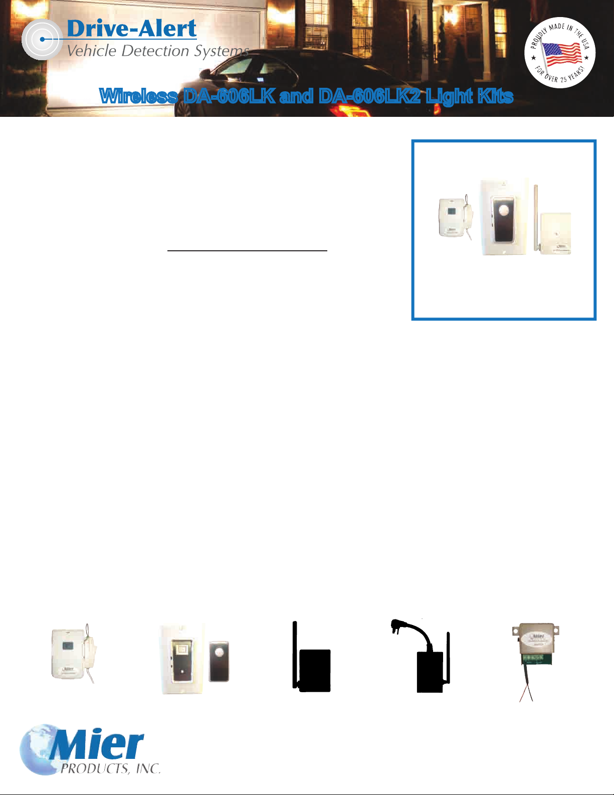
The DA-606LK Light Kit includes a DA-606 Remote Control Transmitter, DA-071
Wall Light Switch Receiver, and a DA-072 Lamp Module Receiver (pictured at right).
The DA-606LK2 Light Kit includes a DA-606 Remote Control Transmitter,
DA-071 Wall Light Switch Receiver, but DOES NOT include a DA-072 Lamp Module.
These parts easily hook up to a DA-600 Wireless Drive-Alert or a DA-605 Wireless
Drive-Alert. However, if using a DA-500 Buried Sensor Drive-Alert you must also
order the additional DA-500LKA Light Kit Adapter (see below and next page).
The DA-073 Heavy Duty Outlet is an optional accessory.
The DA-071 Wall Switch can replace an existing light switch, and the DA-072 Lamp
Module can be used in any outlet to turn on a lamp plugged into the DA-072. The
DA-071, DA-072, and DA-073 are designed for 120 VAC (see load specs on page 4).
All of the components in our Light Kits are FACTORY PROGRAMMED and set to operate as a matched set. If other devices
are purchased later, the DA-606 Remote Control Transmitter will need to be programmed to operate these units. Programming
instructions are provided at the end of this manual. Erasing the factory programming from any unit is also explained.
The DA-606 Remote Control is triggered by a relay closure in a Drive-Alert control panel. This timer control can be set from 1 to
60 minutes. When triggered, the DA-606 transmits a UHF (318 MHZ) coded radio signal to activate the installed DA-071, DA-072,
and or DA-073 devices for the specic time interval that was set. After the preset time interval, the devices will turn off.
The DA-606LK includes:
• one DA-606 Remote Control
• one DA-071 Light Switch with Cover
• one DA-072 Lamp Module
DA-606LK
Wireless Light Kit
The signal path from the DA-606 to any DA-071, DA-072, and DA-073 devices must be unobstructed by metal objects such as
large appliances, or mirrors. Metal objects/mirrors in the signal path may block the activating signals. If the devices are not
working when a Drive-Alert detects a vehicle, in most cases the problem will be solved by moving the DA-606, and/or the devices,
so there is a clear signal path. Use the “TEST” push-button on the DA-606 to verify operation.
For FREE Technical Support contact Mier Products!
Individual Accessories
DA-606
Remote Control
Transmitter
Light Switch with Cover
DA-071
Wireless
DA-072
Wireless
Lamp Module
DA-073
Wireless
Heavy-Duty Outlet
DA-500LKA
Light Kit Adapter
For DA-500 Drive-Alert
800-473-0213 | info@mierproducts.com | www.mierproducts.com
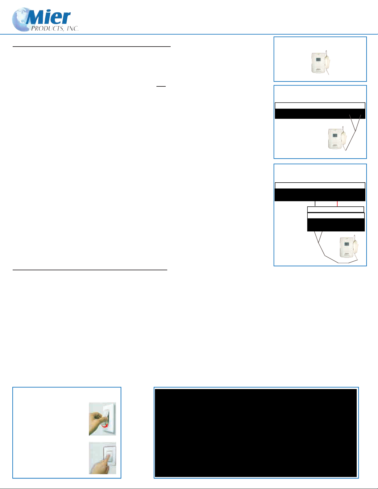
DA-606 Wireless Remote Control Transmitter - activates light switches,
lamp modules, and heavy-duty outlets
Figure A
The DA-606 ts into the magnetic base cradle and attaches to the Drive-Alert control panel.
The switch on the DA-606 (see Figure A) should be ON for Drive-Alert control of the lights.
If you wish to control the lights manually, and bypass Drive-Alert activation of those lights,
such as leaving the lights on during a party so arriving guests’ cars won’t turn the lights on
and off, turn this cradle switch OFF and the Drive-Alert will have no effect on the lights. Other
devices controlled by the Drive-Alert will operate as usual.
When using with a DA-600 or DA-605 Drive-Alert (see Figure B) connect the gray wires
from the DA-606 to the LAST two contacts on to the Drive-Alert control panel terminal board
marked NO and C. The polarity makes no difference.
When using with a DA-500 Drive-Alert (see Figure C) the whistle switch on the control
panel must be in the ON position. The gray wires from the DA-606 go to the FIRST two
contacts on the DA-500LKA Light Kit Adapter. The BLACK wire from the DA-500LKA is
attached to the fourth contact on the DA-500 Drive-Alert control panel marked NEG, and
the RED wire is attached to the sixth contact on the terminal board marked NO.
`
Figure B
DA-600 or DA-605
SIG ALA +5VDC GND +24DC NO NC C NO C
UN REG
Figure C
DA-500 with whistle ON
RED BLACK SHLD NEG +24DC NO NC C
UN REG
Black Red
DA-500LKA
NO C NO NC C
DA-071 Wireless Light Wall-Switch Receiver
CAUTION: Electrical work is required with the installation of the DA-071 Light Wall Switch, and these instructions MUST be
followed carefully. Mier Products recommends you contact a qualied electrician if you are not experienced with electrical work.
Turn off power to the circuit where you plan to install the Wall Switch. WARNING: FAILURE TO TURN OFF POWER AT
THE CIRCUIT BREAKER CAN RESULT IN ELECTRICAL SHOCK CAUSING SEVER OR FATAL INJURY.
First, remove cover (Figure D). The DA-071 Wall Switch is designed to operate a maximum load of 1000 watts at 120 VAC.
Follow Figure E below to install the DA-071. Use the provided wire nuts to secure the connections. Black wire to live black wire,
red to the lamp load, and green wire to ground. After the wires are connected, inspect to insure the wires are securely connected
and none are exposed. Feed the gray antenna wire down into the wall and secure the DA-071 Wall Switch to the wall box. Turn
the circuit breaker back on to apply power. The two (2) blue LEDs on the DA-071 should be on. The Wall Switch has been
factory set to keep the lights on for ve (5) minutes when activated by a Drive-Alert control panel or by manually pushing the button on the DA-606 Light Transmitter. This time can be adjusted from 1 minute up to 60 if the home-owner desires (see Figure F).
Figure D
Remove the cover from
the DA-071 Wall-Switch
prior to installation by
gently pulling it off.
Replace the cover over
the DA-071 Wall-Switch
after installation by
gently pressing into place.
Figure E
Switch Button
Ground (usually
Green copper or green)
Red Load
Live Blue
Black LEDs
Gray Antenna
Do not cut the antenna! SET Button
 Loading...