

Page 1
WIRELESS VEHICLE DETECTION AT ITS BEST!!!
DA-600 & DA-605P INSTALLATION MANUAL
THE BASICS
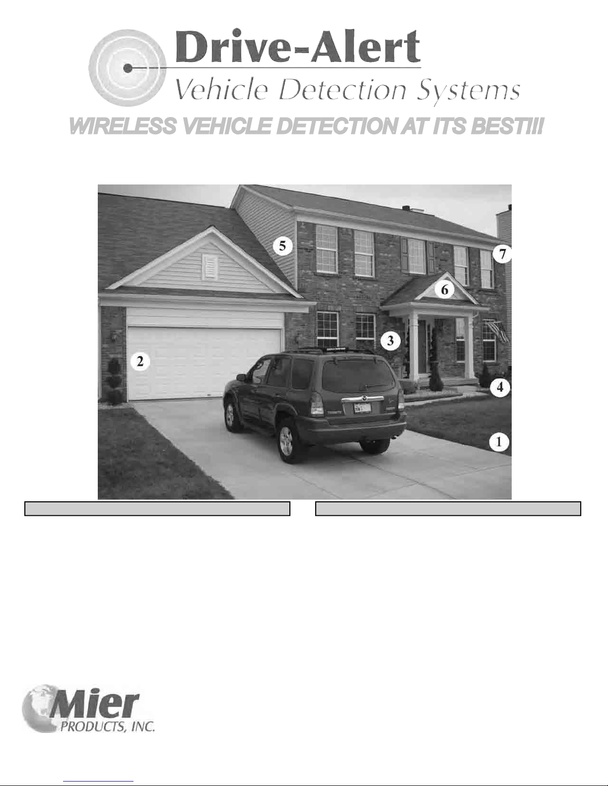
1 A sensor(s) detect(s) a vehicle entering a monitored
area
2 A control panel receives a signal from the sensor
and triggers an alert inside the home or business
MORE OPTIONS
3 Add a remote chime in the front room to alert those
on the rst oor
4 Add another chime in the basement to alert those
downstairs
5 Add a third chime in an upstairs bedroom to alert
those upstairs
6 Add a wireless or hard-wired timer controlled light
kit to turn on outdoor lights, indoor overhead lights,
and/or lamps to warn strangers or welcome friends
7 Attach video surveillance to record activity and
display the driveway on a monitor inside
8 Add a portable chime to alert those in the backyard
pool, garden or deck
9 Activate signs, gates or other equipment
Page 2

TABLE OF CONTENTS
Page Content
Cover Page
1 Table of contents
2 Introduction to the Wireless Drive-Alert Systems
3 Quick Installation Guide
4 Wireless DA-600 Drive-Alert Control Panel and Receiver Installation
5 Wireless DA-600 Drive-Alert Control Panel Terminals, Hooking Up Other Equipment
6 WirelessDA-600,DA-605P,DA-610TO,andDA-611TOSpecications
7 Wireless DA-605P Drive-Alert Control Panel and Receiver Installation
1
8 Wireless Drive-Alert Options - DA-660 Long Range Antenna and Sensor Choices
9 Wireless DA-660 Long Range Reception Booster Antenna Installation Instructions
10-12 Wireless DA-610TO and DA-611TO Sensor/Transmitter Installation (4 pages)
13 Wireless Drive-Alert Accessories: Lights, Chimes, Timer-Controls, Outlets, Sensor-Rocks
14 Technical Support and Warranty Information
15 Troubleshooting Guide
Page 3
INTRODUCTION TO THE 2012 WIRELESS DRIVE-ALERT FAMILY OF SYSTEMS
The Mier Products’ Wireless Drive-Alert Detection Systems give you the benet of easy and economical wireless installation.
All Mier Wireless Vehicle Detection Systems includes 3 components:
1. Receiver
2. Sensor/Transmitter and
3. Sound Annunciator or control
Mier’s Wireless Vehicle Detection Systems are the:
DA-600 containing an internal piezoelectric sounder AND use of Form C Dry Contacts•
DA-605 with integrated “line of sight” transmission to multiple DA-068 plug-in chimes and DA-070 battery powered portable •
chimes that include s choice of three different tones, as well as a set of Form C Dry Contacts
All Mier Wireless Vehicle Detection Systems feature:
UL Listed 110 volt AC plug-in•
+24 volt DC power source for use with accessories•
Relay output available for use by accessories or control (Form C Dry Contacts available)•
Visible POWER LED to monitor power status and LO BATT LED to monitor transmitter batteries•
User accessible address switches to set a unique address code between it and the transmitter•
Normal reception to 1000 feet or ½ mile if using to the DA-660 Booster Antenna (see Options Page)•
Use of an unlimited number of Mier Wireless Transmitters by a Receiver•
100% compatibility with the Mier DA-610TO and optional DA-611TO Sensor/transmitters•
Compatible with Mier Accessories detailed in this manual (See Accessories Page)•
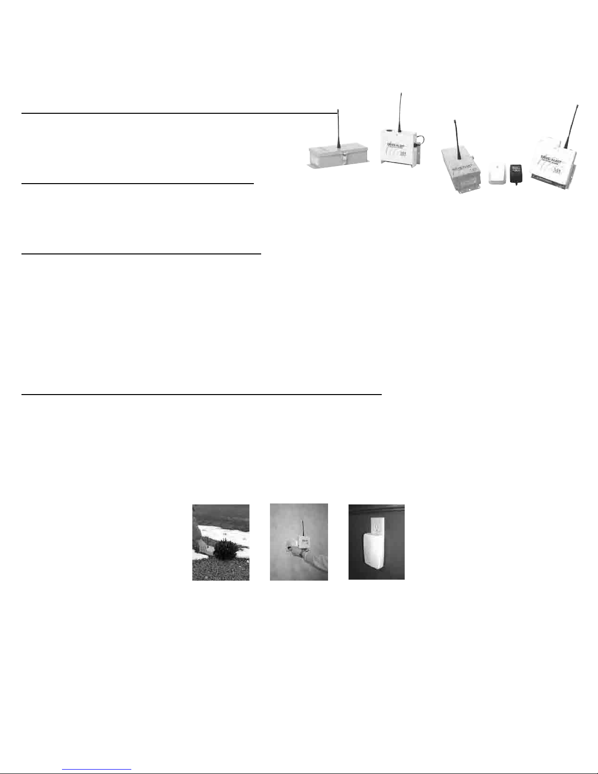
DA-600
DA-605P
2
The DA-610TO Sensor/Transmitter and optional DA-611TO Sensor/Transmitter:
Complete portability•
Operation on 2-AA (LR6) Alkaline or Rechargeable Batteries•
Included circuitry to detect and transmit a low battery condition to the Receiver•
A durable, lockable, standard brick size, weather sealed steel housing with mounting brackets•
Detection of any disturbance in earth’s magnetic eld (moving vehicles) and not people, animals & etc.•
Sensor detection through standard building materials•
EASY INSTALLATION IS OFTEN COMPLETED IN UNDER 30 MINUTES!
AS EASY AS 1, 2, 3 ...
Install 2 - AA batteries in the Sensor/Transmitter, turn it on and place it in the area you wish to monitor1.
Set up the Receiver 4-6 feet above ground inside the home/building and plug it in2.
Test the installation using a vehicle or other moving metal. Then, mount the control panel when performance is satisfactory3.
(4. DA-605P model) Place the Plug-in DA-068 Remote Chime(s), and/or DA-070 Portable Chime(s) in areas where you wish
the audible alert to sound
NOTE: All installations can be easily tested by plugging in the Receiver and turning on the Sensor/Transmitter, in the same
vicinity, which will send a radio signal to the Receiver for about one minute. The sounder or control will respond. If the sensor is
moved after the one minute interval, the receiver will be triggered (ex: walking while carrying the sensor/transmitter will trigger)
Page 4
Wireless Drive-Alert Quick Installation Guide
1) Test the system before installation by:
Plugging in the Receiver. If it has a Whistle Switch (e.g. DA-600) turn it on.•
If the system is equipped with wireless chimes, plug one in nearby the Receiver.•
Opening the lid of the Transmitter, installing 2-AA Batteries and turning on the power switch and observing the valid XMSN •
LED on the Control Panel being lit.
ConrmthattheWhistle,Chimes,LightControlsorotheraccessorieshaveactivated.•
Turn OFF the Sensor/Transmitter and repeat the alarm sequence by turning the power on again.•
ClosetheSensor/TransmitterLid,TurnONpoweronenaltimeandwaitforabout1minuteandthenmovetheSensor/•
Transmitter or wave a steel screwdriver or pliers along the latch side of the unit and observe the sounder and/or accessories
activating.
2) Take the Sensor/Transmitter and place it long ways within 5 feet of the edge of the driveway to be detected at about the
location where you propose to install it. The sensor/transmitter box should be a few inches off of the ground to prevent heavy
rainsfromoodingtheunit.
3) Place the Receiver at least 4 feet above ground in the proposed installation location and plug the power cord into an AC
receptacle. The power light in the lower right hand corner of the Receiver will now be ON.
4) Make certain the annunciators are on:
On models containing a piezo whistle, slide Whistle Switch to ON or •
On models using wireless chimes and/or controls plug-in or install batteries in remote wireless chimes•
3
5) Test the system using a vehicle to pass by the Transmitter @ 5MPH or by swinging a steel shovel along the long side of the
Transmitter setting off the sounder signal.
6)Oncetestingissuccessful,choosethenalmountinglocationsandperformStep6repetitivelyforconsistentdetectionand
nalizeinstallation.
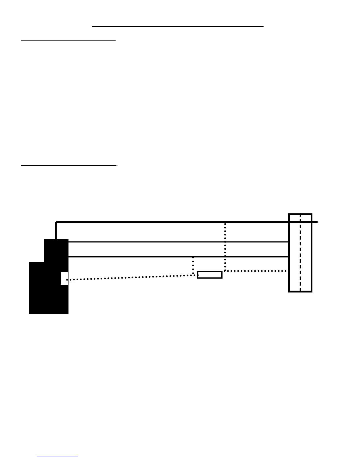
Underground OR Overhead Power or Telephone Lines
40 ft (min)
Garage
Driveway
House 5 ft (max)
1000 ft (max) 60 ft (min)
Control Panel
Sensor
Road
NOTE: AVOID THE FOLLOWING!!!
Putting the Receiver in a basement without the use of a Long Range Antenna & Long Range Receiver•
Hills in the terrain existing between the Transmitter and Receiver of greater than 4 Feet without the use of the Long Range •
Antenna & Long Range Receiver
Burying the Transmitter in the ground.•
Shielding the Transmitter in an Aluminum, Copper or Steel enclosure•
Heavy gauge Aluminum or Steel obstructions in direct path of the line-of-sight from the Transmitter to the Receiver•
Aluminum or Steel electrical enclosures or conduit within 12 inches of Receiver installation•
E-Glass window in the direct path of the line-of-sight between the Transmitter and Receiver•
Receiver mounted behind a Stucco wall without the use of a Long Range Antenna/Receiver mounted so that the Stucco wall •
does not interfere between the Transmitter & Receiver
Mounting Transmitter more than 5 feet from the edge of the driveway to be detected•
Mounting the Transmitter on a tree as they twist in the wind causing false alarms to occur.•
Mounting the Transmitter greater than 4 feet above the ground creating detection misses as most vehicles are non-ferrous •
above the belt line.
Mounting the Control Panel within 10 feet of a wireless modem, cellular phone, or cordless phone•
InstallingtheDA-660ReceptionBoosterantennainanatticwithametalroofoverit(woodandshingleroofsarene)•
Page 5
WIRELESS DA-600 DRIVE-ALERT PAGE 1 OF 3
MODEL DA-600 CONTROL PANEL/RECEIVER GENERAL INFORMATION:
The Model DA-600 Drive-Alert is a direct wireless replacement for the original hard-cabled DA-500 model. An internal piezo
electric whistle acts as the alert and is located inside the control panel. The whistle may be switched off if desired, and when
switched off, the relay contacts are converted to Form C dry contacts. There is also an additional set of Form C dry contacts.
With the whistle switch ON you have one set of Form C dry contacts available, and with the whistle switch OFF you have two
sets. These relay contacts may be supplied with 24 volts DC or used as Form C dry contacts. The DA-600 control panel will operate any of Mier’s Drive-Alert accessories listed on the “Accessories” pages of this manual. It can also be used to control other
external bells, surveillance systems, signs, gates and relays. An adjustable time control provides 2 to 12 seconds of alarm time
for each vehicle detected.
A DA-600 INCLUDES: ONE DA-600 CONTROL PANEL AND ONE DA-610TO SENSOR (pictured here). See the Options and
Accessories pages to customize this system for your particular application.
4
DA-600 Control Panel with a DA-610TO Sensor/Transmitter
DA-600 CONTROL PANEL/RECEIVER INSTALLATION:
The DA-600 receiver is to be mounted inside where 110 volts AC power is available 4-6 feet above ground level. To maximize
transmitter reception the exible antenna is to be at least 12 inches from any metal pipes, power conduits, breaker boxes, etc.
For extended ½ mile range reception, or for mounting below ground, use the DA-600 Long Range system (i.e. DA-600LR) which
includes a factory installed accessory and a DA-660 Long Range Booster Antenna. (See Options page for details)
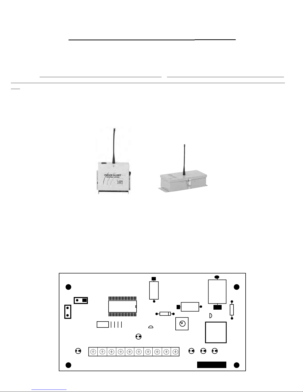
A Red power lamp (see FIGURE 1 labeled LED 1) indicates that the power is on and that the internal 1 Amp Fuse is okay. An
Amber lamp (see FIGURE 5 labeled LED 2) indicates a low battery condition at the Sensor/Transmitter. This lamp will stay on
until the battery voltage in the transmitter is above 2.7 volts DC. NOTE: Before changing batteries, unplug the receiver and wait
at least one minute after replacing batteries before applying power. This prevents unwanted alarms and resets the low battery
detector.
+
GND
ANT
ON
SW1
SW2
SW3
OFF
LED 4
VALID
SIG +5V ALA GND +24V NO NC C NO C
XMSN
DC DC
SW4
TB1
LED 4
VALID
XMSN
TIME
+
MAX
MIN
LED 2 LED 3 LED 1
LO ALARM POWER
BATT
ALERT
+
FUSE
1 AMP
FIGURE 1
Page 6
WIRELESS DA-600 DRIVE-ALERT PAGE 2 OF 3
Under the unit cover are the address code switches (see FIGURE 1: SW1, SW2, SW3, SW4 in left lower quadrant) that must be
set to match those in the transmitter. These switches are preset at the factory for code 0000. They should only be changed if
the transmitter code is also changed. Also there is an alarm time control (see FIGURE 5 TIME near middle) which is preset at
minimum of 2 seconds of alarm time. The maximum alarm time is 12 seconds. LED 4 (VALID XMSN) is on when the Receiver
detects a valid transmission of its address and LED 3 (ALERT) is on when the relay is closed. On the outside of the Receiver is
a WHISTLE ON-OFF switch. This switch basically provides or removes the 24 volt DC available at the relay output. The
common contact of the relay receives 24 volts DC from this switch. In the “whistle off” position, the relay provides Form C dry
contacts for external device control.
DA-600 CONTROL PANEL TERMINALS:
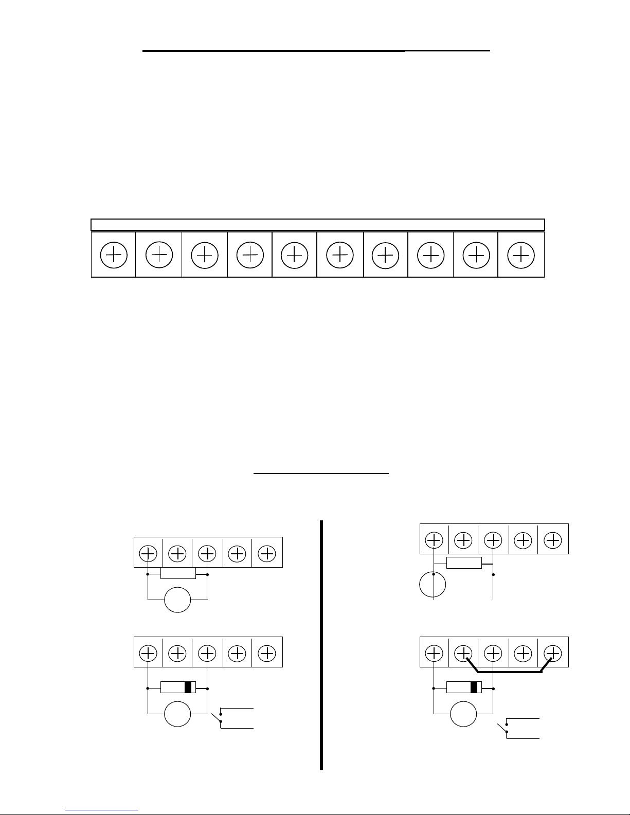
The terminal block, TB1, provides a convenient wire connection point for external device control and test points (See FIGURE 2
for a detailed description of the contacts available).
SIG ALA +5VDC GND +24VDC NO NC C NO
FIGURE 2
SIG - Received Signal Strength (e.g. 1-1.5VDC = No Signal; 1.6-2.5VDC = Signal•
+5VDC - 5 Volt DC Logic Power @ 25mA (max)•
ALA - Alarm Signal (0-1vdc = No Alarm; 4-5 VDC = Alarm)•
GND - Unit Ground•
+24VDC - Power Supply for 24VDC @ 100 mA (.1 amp) maximum accessories•
NO - Normally Open Relay Contact•
NC - Normally Closed Relay Contact•
C - Common Relay Contact•
NO - Normally Open Relay Contact•
C - Common Relay Contact•
NOTE: The DA-600 receiver will operate on 12 VDC. An auto battery with the positive (+) connected to the +24 VDC terminal
and negative (-) connected to the GND terminal will operate the DA-600. Therefore, the control panel can become portable (the
sensor is always portable) so the unit can be used in a vehicle or at a remote site.
NOTE: DO NOT PLUG THE UNIT INTO 110 VAC IF OPERATED ON BATTERY AS IT CAUSES FAILURE
C
5
Figure 3A shows a typical DA-600 control panel connection to an accessory and with the whistle ON
Figure 3B shows a typical DA-600 control panel connection to an accessory with the whistle OFF
Connection using relay contacts switching internal power
GND +24V NO NC C
External 24VDC Bell
DA-500 Whistle Switch ON
NOTE:
Limit of two external bells
Connection using relay contacts switching internal power
GND +24V NO NC C
External Relay Hookup
24VDC
NOTE: If internal piezo whistle is not wanted, move the DA-500 Whistle Switch to
the OFF position and connect the jumper between +24 and the C Terminal
BELL
RELAY
Capacitor
0.1 Microfarads 100 Volt (min)
Adding a capacitor extends the
life of the relay.
1N4004 DIODE
Adding the diode extends
the life of the relay.
To AC operated
CHIMES/ALARMS
Maximum Current
Limited to 1 Ampere
Maximum Voltage is 24V
DO NOT apply 120VAC
+24VDC External Relay
Limited to
100 Milliamperes
Connection using dry contacts and external power
GND +24V NO NC C
BELL
External Power
Connection using relay contacts switching internal power
GND +24V NO NC C
RELAY
FIGURE 3A FIGURE 3B
Capacitor
0.1 Microfarads 100 Volt (min)
Adding a capacitor extends the
life of the relay.
“Jumper” added
1N4004 DIODE
Adding the diode extends the life
of the relay.
To AC operated
CHIMES/ALARMS
or Panel Function
Page 7
WIRELESS DA-600 PAGE 3 OF 3
DA-600, DA-605P, DA-610TO & DA-611TO SPECS
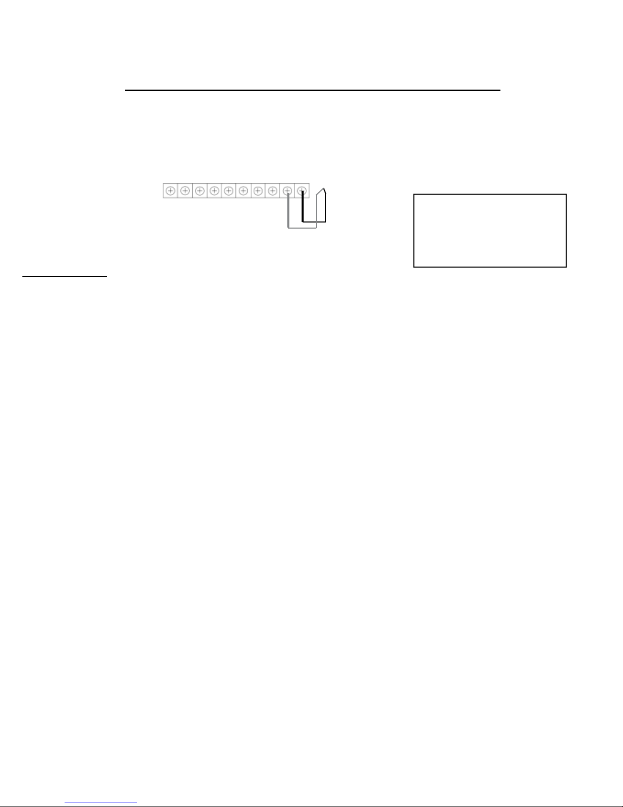
Figure 4 shows a typical DA-600 control panel connection to a “line of sight wireless transmitter” like our DA-066, with the whistle
ON or OFF
DA-600 with WHISTLE ON or OFF
6
SIG ALA +5VDC GND +24DC NO NC C NO C
UN REG
DA-066 Push-Button Wireless
Chime Transmitter
If your Drive-Alert does not
Red wire to “NO”
Black wire to “C”
Red Black
look like this, you may have
an older model. Please call
FIGURE 4
Mier’s free tech support line
at 800-473-0213
SPECIFICATIONS:
DA-600 and DA-605P CONTROL PANEL/RECEIVER:
1. INPUT POWER: 120 VOLTS AC 50-60 HZ, 3 WATTS
2. OUTPUT POWER: 24 VOLTS DC AT 100 MILLIAMPERES (.1 AMP)
3. FREQUENCY: 433.92 MHZ FIXED SUPERHETRODYNE
4. ANTENNA: ¼ WAVE MONOPOLE FIXED BOLTED IN STEEL CASE 0 DBI GAIN
5. RECEIVER: LINX TECHNOLOGIES MODEL KH2
6. ADDRESS CODES: FOUR POSITION DIP SWITCH
7. LAMPS/LEDS: POWER=RED, LO BATT=YELLOW, VALID XMSN=RED, ALARM=RED
8. OUTPUT: PIEZO WHISTLE AND 24 VOLT RELAY
9. ALARM TIME: ADJUSTABLE 2 TO 12 SECONDS FOR EACH ALARM.
10. OPERATING TEMP: 0 DEGREE F. TO +105 DEGREE F.
11. WEIGHT: 2.5 POUNDS.
DA-610TO SENSOR/TRANSMITTER:
1. POWER REQUIREMENTS: TWO (2) SIZE AA (LR-6) BATTERIES 3.0 VOLTS DC
2. OPERATING FREQUENCY: 433.92 MHZ FIXED
3. ANTENNA: 1/4 WAVE MONOPOLE BOLTED INTO THE STEEL CASE. 0 DBI GAIN
4. TRANSMITTER OUTPUT: 2 MILLIWATTS
5. TRANSMITTER: LINX TECHNOLOGIES MODEL KH ENCODER/TRANSMITTER
6. ENCODER MODULATION: AMPLITUDE ON-OFF KEYING (OOK) AT 1200 BPS.
7. ADDRESS CODES: FOUR POSITION DIP SWITCH SELECTED FOR THE ENCODER
8. DATA: ONE DATA BIT ENCODED WHEN BATTERY IS LOW.
9. TRANSMITTER ON TIME: LESS THAN 5 SECONDS FOR ANY SINGLE ALARM
10. ENCLOSURE: 18 GAUGE GALVANEAL PAINTED STEEL WITH WEATHER SEAL AND LOCKABLE
LATCH CLOSURE. HOUSES THE TRANSMITTER AND SENSOR
11. QUIESCENT CURRENT : 60 MICROAMP
12. ACTIVE CURRENT: 3 MILLIAMP
13. BATTERY LIFE: ABOUT ONE YEAR IN RESIDENTIAL USE.
14. OPERATING TEMP: -40 DEGREES F TO + 125 DEGREES F
15. WEIGHT: FOUR POUNDS
16. DETECTION OF VEHICLES: DISTANCE FROM SENSOR/TRANSMITTER UNIT FOR STANDARD SEDAN MOVING
AT 5 MPH+ IS 14 FEET (MAX), 9 FEET (MID), 7 FEET (MIN)
DA-611TO SENSOR/TRANSMITTER:
ALL SPECIFICATIONS ARE THE SAME AS THOSE LISTED FOR THE DA-610TO ABOVE, EXCEPT THE FOLLOWING:
A. THE SENSOR IS NOT INSIDE THE ENCLOSURE WITH THE TRANSMITTER. IT IS AN EXTERNAL SENSOR
ATTACHED TO THE TRANSMITTER ENCLOSURE WITH 50’ OF CABLE (SEE OPTIONS PAGE)
B. DETECTION OF VEHICLES: DISTANCE FROM SENSOR/ FOR STANDARD SEDAN MOVING AT 5 MPH+ IS
17 FEET (MAX), 12 FEET (MID), 10 FEET (MIN)
Page 8
7
WIRELESS DA-605P DRIVE-ALERT
DA-605P CONTROL PANEL/RECEIVER GENERAL INFORMATION:
The DA-605P Drive-Alert’s receiver board is the same as the one used in the DA-600 receiver (see FIGURES 5-6). However,
the DA-605P does not have an internal whistle, nor a whistle switch. The advantages of the DA-605P over the DA-600 are the
DA-066 wireless chime transmitter which activates remote chimes as an alert. Any combination or quantity of the DA-068 Plug-in
Chimes and/or the DA-070 Battery-powered Portable Chimes may be used. Each chime is activated by a radio signal from the
DA-066 attached to the control panel. (See Accessories page). These chimes have a choice of three tones and volume control,
and can be used up to 100’ away from the control panel. As stated, the DA-068 plugs into any standard wall outlet and can be
easily hidden behind furniture. The DA-070 can be taken into the backyard, out to the pool & etc.
If your Drive-Alert does not
look like this, you may have
an older model. Please call
Mier’s free tech support line
at 800-473-0213
DA-605P Control Panel with one DA-068 Plug-in Remote Chime and a DA-610TO Sensor/Transmitter
(Optional DA-070 Battery Operated Portable Chime pictured on Accessories Page)
TESTING FOR RADIO TRANSMITTER COMMUNICATION:
The alarm signal is used to turn on the 315 MHz radio signal in the push button located on the top of the DA-605P, which will
sound the remote chime. This signal will reach at least 100 feet to the chime. The radio module located on the top of the housing
contains a user accessible push button for test or “call” purposes. Internal to the module a 12 volt battery type A23 is contained
and should last about 3 years. This battery is activated only when testing the radio module to chime signal path and does not
have an effect on Drive-Alert operation. The chime can be tested independent of the Drive-Alert by pushing the button causing
the chime to sound. The enclosure of the radio module can be opened by pushing in on the bottom latch carefully with a screwdriver and lifting up. Both the jumpers as well as the battery are now accessible. To re-seat the radio module enclosure carefully
align and place the enclosure top locking tabs and carefully push in the bottom latch until it snaps closed. The DA-068 Plug-in
Chimes and DA-070 Battery-powered Portable Chimes are factory preset for an 8 note Westminster tone. To change the sound
to a two note tone, remove jumper #8 under the small cover on the back of the chime, To obtain a 1 note tone, remove only the
jumper from the radio module while leaving the jumper in the chime.
INSTALLATION:
For Sensor/Transmitter installation details see the sensor installation pages. The DA-068 & DA-070 chimes may be located in
multiple rooms and locations and the DA-605P can chime an unlimited number of chimes within 100+ feet of the Control Panel.
Simply plug the Control Panel in a standard wall outlet, in an out of site space where the signal from the DA-610 Sensor can
reach it. Plug in the DA-068 Remote Chime(s) and place the DA-070 Portable Chimes in an area(s) of the house where an alert
is desired. The DA-068 volume control is accessible on the back panel of the chime. However, the DA-070 must have its back
removed to gain access to the volume control. The DA-070 Battery Operated Portable Chime needs three D size batteries which
will last about 3 years. For all options and operation instructions of the chimes, see the instructions enclosed with the chimes.
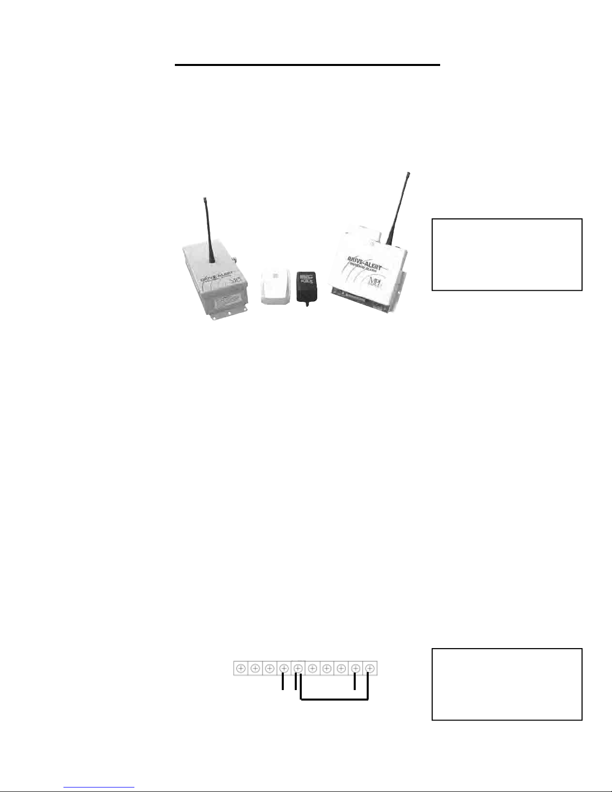
Figure 5 shows a typical DA-605P control panel connection to a “line of sight wireless transmitter” like our DA-606LK Light Kit
DA-605P to a DA-606LK
SIG ALA +5VDC GND +24DC NO NC C NO C
UN REG
If your Drive-Alert does not
look like this, you may have
an older model. Please call
Black Red Green
Blue “jumper”
FIGURE 5
For DA-605P control panel and DA-610TO/DA-611TO sensor specications, see previous page 6.
Mier’s free tech support line
at 800-473-0213
Page 9
8
WIRELESS DRIVE-ALERT OPTIONAL ANTENNA AND SENSORS
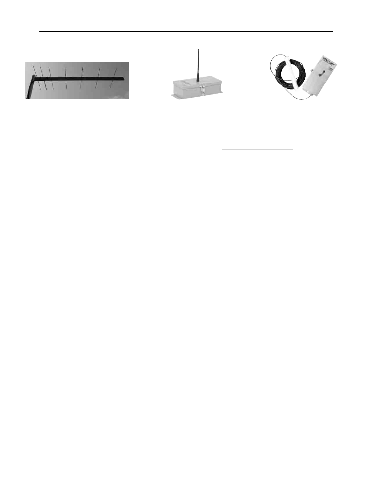
DA-660 DA-610TO DA-611TO
The DA-660 Long Range Antenna is an option that can be used with all of Mier’s Wireless Drive-Alert Systems to boost the
reception-range from the sensor to the control panel up to 1/2- mile. This is a factory installed accessory and must be ordered at
the time of purchase by adding an “LR” to the end of the part number. Example: a DA-600 or DA-605P Drive-Alert with the with a
DA-660 long range option would be a DA-600LR or DA-605PLR.
The DA-610TO Sensor/Transmitter is the standard sensor that comes with a DA-600 or DA-605P. The sensor and transmitter
are encased inside a durable NEMA 4 outdoor enclosure (see the DA-611TO if an external sensor is needed). The DA-610TO
monitors a 14 foot radius (28 foot sphere). Mier’s sensors/transmitters require two AA batteries which will last more than a year
under normal residential usage. These sensors may be placed up to 1000 feet from the control panel, and up to 2500 feet when
used with an “LR” system which includes the DA-660 Long Range Reception Antenna. The sensors are tamper resistant due to
the fact that if anyone touches or moves one, the alert will be triggered.
The DA-611TO Sensor/Transmitter is an optional wireless sensor that can be used in place of, or in conjunction with, the
standard DA-610TO Sensor that comes with a DA-600 or DA-605P Drive-Alert. The DA-611TO is used in applications where
it is impossible to place a DA-610TO close to the driveway or area needing monitoring. The DA-611TO allows you to bury the
sensor right next to, or under, the driveway and then place the transmitter up to 50 feet away under some landscaping or up a
tree/pole (which also helps increase transmission reception). If you want this option without the standard DA-610TO, order a
Drive-Alert control panel only by adding a “CP” to the end of the part number as well as the DA-611TO. Example: a DA-600 or
DA-605P Drive-Alert with the DA-611TO would be a DA-600CP or DA-605CP and a DA-611TO. Note: If you order a DA-605CP,
make sure you also remember to order DA-068 and/or DA-070 chimes too. An unlimited number of, or combination of, wireless
sensors may be used to monitor several areas.
NOTE: If needed, Mier’s wireless systems can be completely battery operated allowing them to be entirely mobile.
See the following pages for Installation Instructions of these options
Page 10
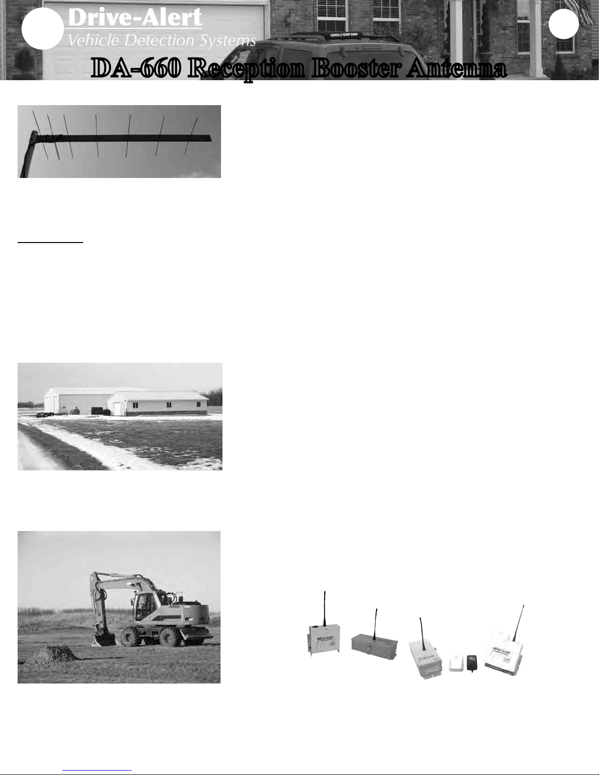
DA-660 Reception Booster Antenna
DA-660
The DA-660 pictured here is mounted on a
pole. The antenna may be mounted indoors
or outdoors. Typically, it is mounted hidden
inside the attic of a home or business.
Specications:
Weight - 1.2 lbs.
Length - 36 inches
Width - 13 inches
Height - 1.5 inches
Frequency - 434 mHz
Impedance - 75 Ohms
Gain - 10.6 dB
Type - 7 element Yagi
9
• When a monitored location is more than 1000’ away, the DA-660 is the perfect
accessory for the DA-600 or DA-605P wireless Drive-Alert Vehicle Detection Systems.
• This antenna boosts the normal Drive-Alert range up to 1/2-mile
• The antenna measures 36” long, 13” wide, and 1.5” high.
• It weighs approximately 1 pound.
• This is a FACTORY INSTALLED ACCESSORY due to the fact that some components
must be changed on the control panel for long range applications
• When ordering you must specify which Drive-Alert model you will be using and add
“LR” to the end of the part number. Example: DA-600LR or DA-605PLR will be a
complete system with the DA-660 Booster Antenna included
• Retro-ts must be shipped back to Mier Products for installation of the components
needed for the long range antenna
STAY CLEAR OF POWER LINES WHEN INSTALLING!
The antenna is equipped with clamps at the rear of the antenna for mounting to one inch
mast pipe. One inch schedule 40 PVC pipe works well for a mast. Removing the end of
the clamps allow mounting on a at surface. The antenna can also be mounted indoors
such as an attic space. Simply lay the antenna across the rafters.
For maximum range and best reception of the transmitter/sensor the antenna should be
pointed at the signal source. The mounting clamps are the back of the antenna.
The connecting coaxial cable should be securely fastened to the antenna connector and
clamped to the boom with the cable wire tie supplied. Use standard 75 Ohm TV cable,
RG-6/U, available at many home stores. If used outdoors, wrapping the connector with
black plastic tape will give many years of use. Connect the other end of the cable to the
control panel.
After mounting and connecting the antenna, turn on the DA-610 transmitter/sensor in the
vicinity of the control panel to check that the system is working properly. If the system is
responding correctly, the DA-610 can be mounted in the desired location on the drive.
The DA-660 is the perfect option for
monitoring remote buildings or equipment up
to 1/2 mile away.
This Factory Installed Option
works with any Wireless Drive-Alert Model
DA-600
DA-605P
Please contact us with any product, tech support, or installation questions.
Don’t forget to check out our website for cut-sheets, installation manuals, and
information on more products!
Page 11
Wireless Sensor Installation page 1 of 3
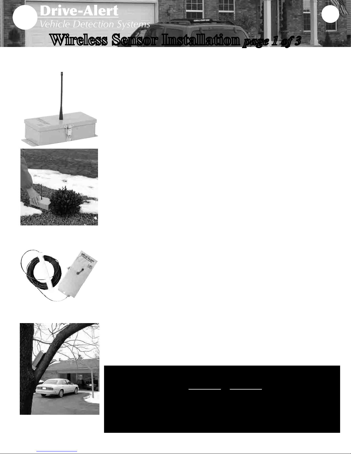
The DA-610TO Sensor/Transmitter comes standard with all of Mier’s wireless Drive-
DA-610TO
Alert Vehicle Detection Systems. This sensor detects the movement of metal within 14’ in
every direction, and sends a signal back to the control panel up to 1000 feet away. See the DA-
611TO below if you are not able to place the sensor right next to the drive, and see the DA-660
to boost the reception range between the transmitter and control panel up to 1/2-mile.
The DA-610TO detection threshold is set by a sensitivity control on the transmitter circuit
board. Maximum sensitivity adjustment is clockwise and minimum is counter-clockwise. In
most cases the factory sensitivity and address code setting will function for the installation. If
a unique address code is needed (e.g. interference from a neighboring Mier wireless system)
open the top cover and adjust the blue and white rocker switches labeled ADDRESS in both
the DA-610TO AND the Control Panel so they are different than factory spec and still match.
The DA-610TO should be placed next to the drive or area to be monitored, and at least 40 feet
from any road trafc to prevent false alarms. Reducing sensitivity would reduce detection of
road trafc, but would also reduce the detection sensitivity in the driveway. The sensor can
be placed in any orientation, parallel or perpendicular to the drive. Any movement of the
sensor will cause an alarm for asset protection. Transmitting range from the sensor to the
control panel in the home is 500’ if placed on the ground, and up to 1000’ if mounted 2-4’ high
on a post (metal, wood or concrete) or a convenient building. Long-range “LR” Drive-Alerts
include a DA-660 reception booster antenna and increases this range up to 1/2-mile!
10
DA-611TO
DA-611TO installation illustration of
the sensor buried under the drive and
the receiver hidden in a nearby tree.
If occasional false alarms occur, reduce sensor sensitivity by turning the small brown
sensitivity control slightly counter-clockwise. Lightning strikes cause a large disturbance in
the magnetic eld, so nearby strikes will cause a a false alarm. It is also possible for electrical
current variations in nearby power lines to cause a false alarm.
The DA-611TO Remote-Sensor/Transmitter is an option which is identical to the
standard DA-610TO with one exception: the DA-610TO sensor is inside the transmitter box,
but the DA-611TO sensor is outside and attached to the transmitter by a 50’ cable. This
allows the sensor probe to be buried under or next to the driveway or area to be monitored, and
the transmitter box to be hidden up to 50’ away or placed high above ground for better range.
For most installations, the DA-611TO sensor should be buried 6 -12 inches below ground and
the cable 3 - 6 inches below ground. Mier HIGHLY RECOMMENDS burying the cable in
1/2-inch PVC pipe to protect it.
NOTE: Try the system above ground temporarily before burying. The entire system, probe,
cable and transmitter can be installed above ground if there is little risk of probe or cable
damage and the probe cannot move. Any movement of the probe will trigger an alarm.
Both sensors are powered by two AA batteries which last one year in residential applications.
Detection-distance from the sensor for a standard-size modern sedan moving 5MPH
DA-610TO DA-611TO
Maximum sensitivity 14 feet 17 feet
Factory set sensitivity 13 feet 16 feet
75% sensitivity 11 feet 14 feet
50% sensitivity 9 feet 12 feet
Minimum sensitivity 7 feet 10 feet
Page 12

WIRELESS DRIVE-ALERT SENSOR INSTALLATION page 2 of 3
DA-610TO (standard) DA-611TO (Option)
Transmitter/Internal Sensor Transmitter/External Sensor
The Model DA-610TO (or optional DA-611TO) Sensor/Transmitter contains the sensing and transmitting electronics and is to be
placed in the area of detectable moving vehicles. The detection threshold is set by a sensitivity control (See FIGURE 6: lower
Right Hand quadrant) on the transmitter circuit board. Maximum sensitivity adjustment is Clockwise and minimum is CounterClockwise. In most cases the factory sensitivity and address code setting will function for the installation. If a unique address
code is needed (e.g. interference from a neighboring Mier wireless system) open the top cover revealing the transmitter circuit
board. Look for the blue and white rocker switches labeled ADDRESS in the lower middle of the circuit board.
11
FIGURE 6
The address code switches are factory preset to OFF, in other words all 0’s (e.g. 0 = OFF then 1 = ON). To set 1001, switch
1= ON, switch 2 = OFF, switch 3 = OFF, switch 4 = ON, and etc. The corresponding Receiver address MUST match this
Sensor/Transmitter address for reception from this Sensor/Transmitter.
The Sensor/Transmitter operates on 2 - AA batteries providing 3.0 volts DC to the electronics. When battery voltage reaches 2.7
volts a signal is transmitted and the LO BATT LED is lit in the Receiver. The transmitter continues to operate for a time but new
batteries will be needed for uninterrupted operation. Typical battery life is 1 year in a residential installation with Alkaline
batteries. To install batteries, unlock and open the cabinet door, turn off the Power switch, remove and install batteries, observing
the correct polarity. Turn on the Power switch, close and lock the cabinet door. When working on the transmitter, it is advised to
unplug the Receiver to prevent false alarms. An LED marked XMSN near the center indicates the transmitter is currently
transmitting. A jumper marked as TX_TEST near the top puts the Sensor/Transmitter into a “continuous transmit” mode when the
jumper is in the TEST position. Both of these are meant to be used during setup and troubleshooting.
*NOTE: The optional DA-611TO (Options Page) is used in cases where it is impossible to securely place the DA-610TO near the
drive or area that needs monitoring, but it still provides the same sensing & wireless performance.
Page 13
12
WIRELESS DRIVE-ALERT SENSOR INSTALLATION page 3 of 3
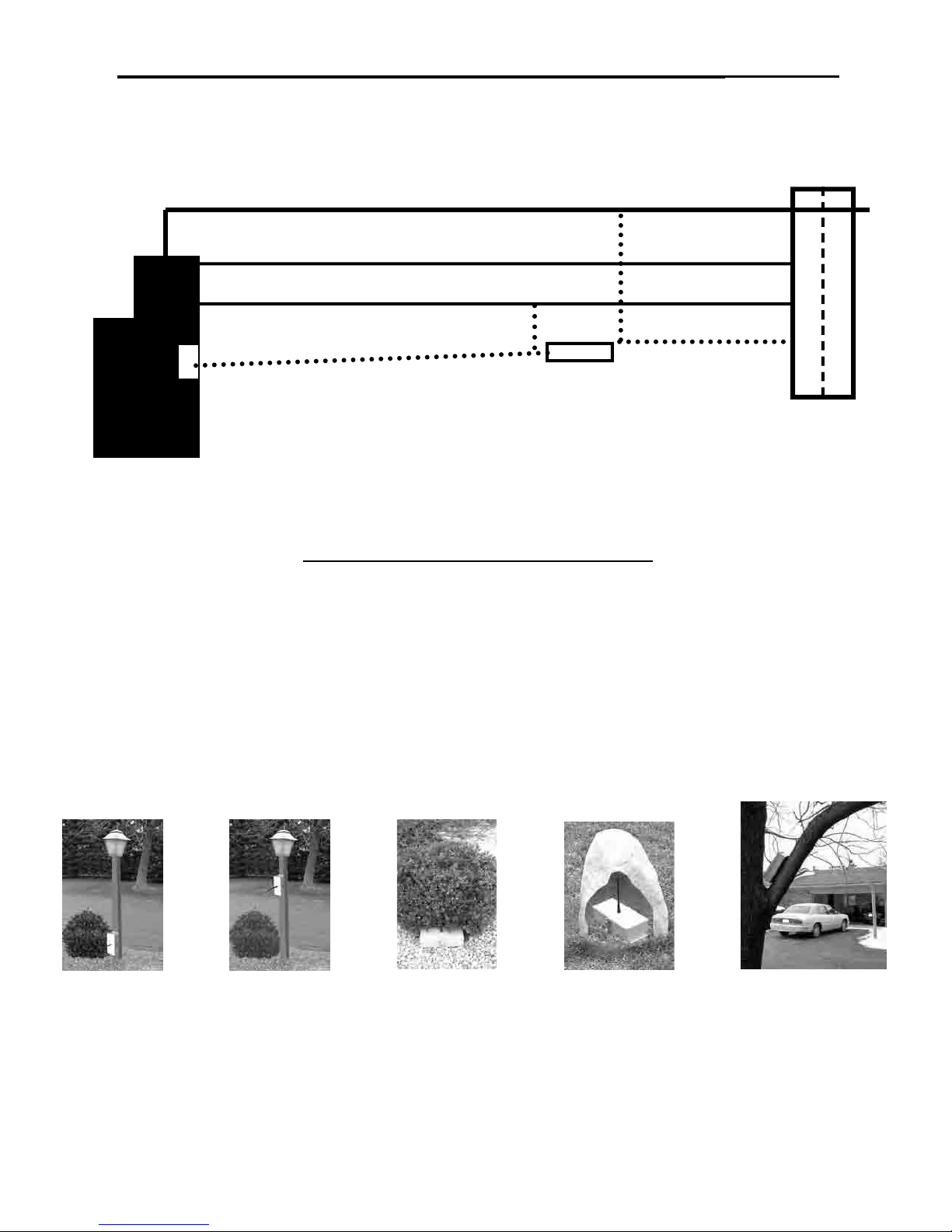
With factory settings, install the Sensor/Transmitter at least 60 feet from streets or roads (see FIGURE 7). FIGURE 7 illustrates a
typical installation for all receivers and sensor/transmitters.
Underground OR Overhead Power or Telephone Lines
40 ft (min)
Garage
Driveway
House 5 ft (max)
Sensor
60 ft (min)
1000 ft (max)
Control Panel Road
FIGURE 7
To aid in reliable transmitter installation, please follow these DO’s and DON’Ts:
TRANSMITER INSTALLATION DO’s and DON’Ts
1. DO mount DA-610TO enclosure or the sensor of the optional DA-611TO parallel to the driveway
2. DON’T point the antenna at the passing vehicle
3. DO mount the DA-610TO enclosure or DA-611TO sensor securely. IT MUST BE STABLE AND
MOTIONLESS! Any movement of the sensor will cause an alarm.
4. DON’T mount the DA-610TO on a tree. If a tree mount is needed use the optional DA-611TO.
5. DO avoid power surges (any lightning or power surges in the sensor area will cause false alarms)
For a simple driveway installation, the unit can be turned on, locked, and placed a few inches above the ground near the drive
and the signal will still be received by the Control Panel up to 500 feet away (line of sight).
Some mounting options are to cover it with a fake rock (see DA-ROCK1 on accessories page) or other non-metallic cover, place
the box in a nearby bush, or rmly bolt the case to a STABLE wood, plastic, or metal post. A 4X4 mailbox or fence post may be
used. The unit can be bolted inside or outside a buildings wall.
DA-610TO DA-610TO DA-610TO DA-610TO DA-611TO
Low on a post High on a post Under a bush Under a DA-ROCK1 High in a tree with sensor
under the drive
NOTE: Any moving metal objects such as a gate, metal fence or metal garage door that may move with wind should be considered and located outside the detection range to minimize false alarms that could occur.
Page 14
WIRELESS DRIVE-ALERT ACCESSORIES
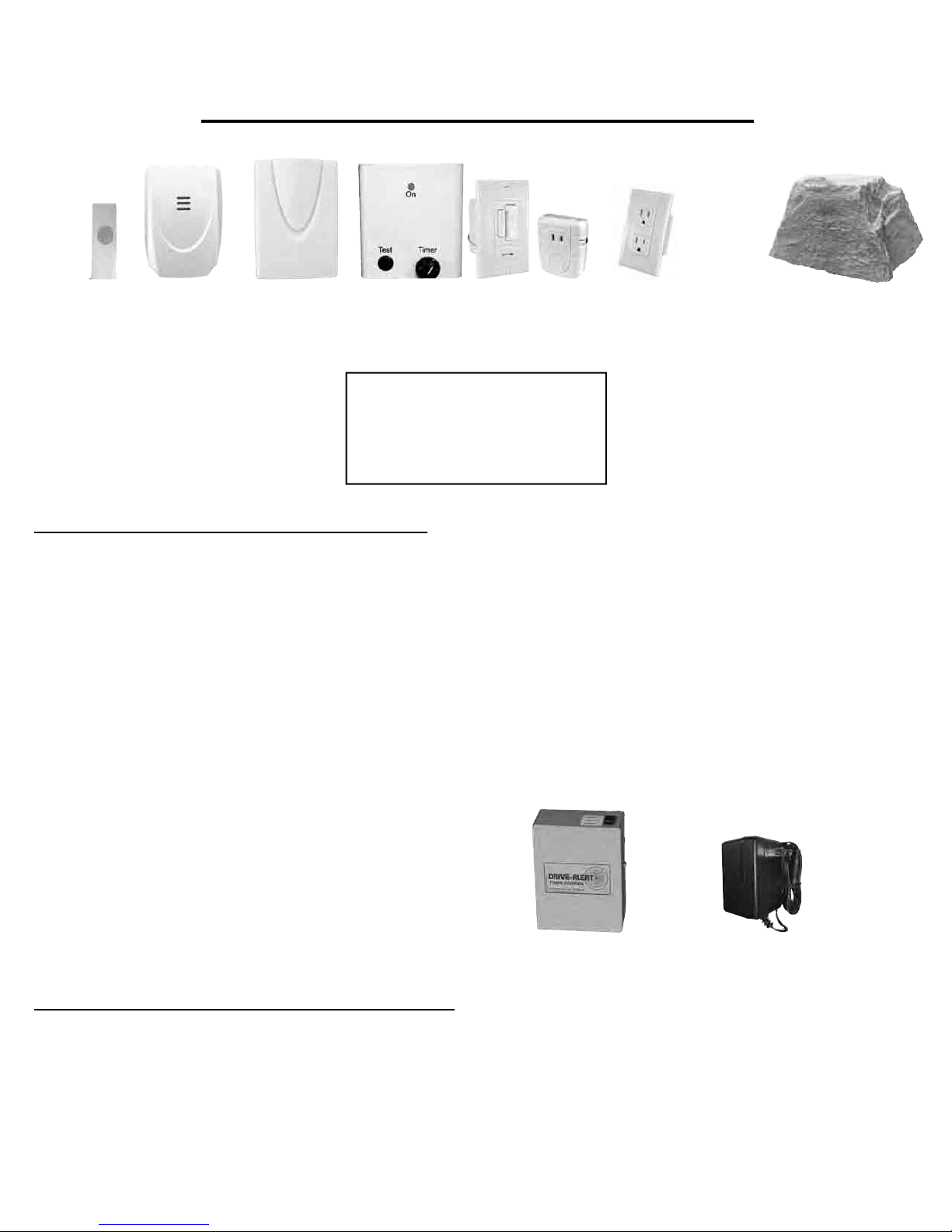
DA-066 DA-068 DA-070 DA-606LK DA-073 DA-067 DA-ROCK1
(DA-606, DA-071, DA-072)
If your Drive-Alert accessories
do not look like these, you may
have older models. Please call
Mier’s free tech support line at
800-473-0213
13
WIRELESS DRIVE-ALERT ACCESSORIES:
The DA-066 Remote Chime Transmitter• is used in combination with the wireless DA-068 Remote Plug-in Chime(s) and/
or the DA-070 Battery-operated Portable Chime(s) in applications where a more pleasant chime and alerts in more rooms/
areas of a home are desired. This is standard on the DA-605P. Any number and combination of plug-in chimes and portable
chimes may be used.
The• DA-606LK Wireless Light Kit comes with a DA-606 Timer Control, one DA-071 Light-Switch, and one DA-072 Lamp
Module. Any number and combination of light-switches and lamp modules may be used. For heavy-duty applications the
DA-073 Heavy-Duty Outlet includes a top receptacle that handles up to a maximum of 1800 watts or maximum of
15 amps.
The DA-067 Antenna Stabilizer • is used with the DA-610 or DA-611 Sensors to prevent transmitter antenna vandalism
(i.e. animal or human) protection and/or environmental stability (i.e. high wind, blizzard conditions, animals perching, etc.).
The DA-ROCK1 • is a popular accessory with all of our wireless systems, and is used to hide the DA-610 Sensor
DA-655 DA-052V DA-505 DA-050
HARD-WIRED DRIVE-ALERT ACCESSORIES:
The Hard-Wired DA-655 Chime with Volume Control• is our most popular accessory for the model DA-600 Drive-Alert in
Drive-up Window or business applications!
The DA-052V Whistle with Volume Control• – is used with the DA-600 when a second whistle is desired (hard-wired
installation)
The Hard-Wired DA-505 Timer Control• is used to with the DA-600 to turn on lights when the sensor detects a vehicle.
The DA-050 Power Pack• is a replacement power-pack/transformer for the Drive-Alerts.
Page 15

14
Mier Products’ Drive-Alert Technical Support
Mier Products, Inc. provides free telephone and email technical support for all of our Drive-Alert vehicle detection
systems. Call us at 800-473-0213 between the hours of 8:00 am and 5:00 pm EST, send an email to
[email protected], or download our Cut-Sheets, Instruction Manuals, or FAQs from our website:
www.mierproducts.com
Mier Products’ Drive-Alert Warranty
Limited Warranty for Drive-Alert Models and Accessories Manufactured by Mier Products, Inc.
Mier Products, Inc.’s Limited Warranty Program for Drive-Alert models and accessories protects the original owner
for one year from the date of purchase against defects in original parts or workmanship. Mier Products, Inc. agrees to
repair or replace parts (Mier’s option) that are deemed defective by our Quality Control Team, without charge for parts
or labor, if the defective unit is returned prepaid to Mier Products, Inc., Kokomo, IN, 46901, within the one-year period.
Close inspection at the time of receipt by the customer will quickly determine product quality. Thus, Mier Products, Inc.
recommends inspection of Drive-Alert models and accessories immediately upon receipt, before installation or driving
to an installation site, and contacting Mier Products, Inc. if quality issues arise.
NOTE: Sensors and cables that have been buried are not covered. Wireless sensors that have been sitting in ooded
areas or standing water are not covered.
Mier Products, Inc. does not assume responsibility for claims or damages caused by improper installation or use of
these products, accessories, and/or products connected to them. Mier Products, Inc. does not assume responsibility
for damages to these products or their accessories due to shipping damage or damage occurring while in a customer’s
warehouse and/or possession. Mier Products, Inc. does not assume responsibility for damage due to accident, faulty
wiring, overload of Drive-Alert or Drive-Alert accessory output, or components attached to the Drive-Alert parts.
Drive-Alert accessories and parts built by other OEMs (including but not limited to chimes, lamp modules, light
switches, bells, splice kits) are covered under their respective OEM warranties. Drive-Alert models and accessories
must be shipped, handled, stored, and installed with strict adherence to OEM installation instructions.
This warranty constitutes the entire warranty with respect to Mier’s Drive-Alert Models and Accessories and IS IN LIEU
OF ALL OTHERS, EXPRESSED OR IMPLIED, INCLUDING ANY WARRANTY OR MERCHANTABILITY AND
WARRANTY OF FITNESS FOR A PARTICULAR PURPOSE AND IN NO EVENT IS MIER PRODUCTS, INC., OR IT’S
OEM PARTNERS, RESPONSIBLE FOR ANY CONSEQUENTIAL DAMAGES OF ANY NATURE WHATSOEVER.
Any warranty OR sales questions should be directed to Mier Products at 800-473-0213, or via e-mail to
[email protected]
Repair work not covered by this Warranty is available for a nominal charge.
800-473-0213 | [email protected] | www.mierproducts.com
Wireless Vehicle Detection | Buried Sensor Systems | Driveway Alarms | Drive-Up Window Detection |
Instrument Boxes | DVR & CPU Lockboxes | Flush-Mount Cabinets | NEMA Outdoor Enclosures | NEMA
Temperature Controlled Enclosures | NEMA Rack Enclosures | Rack Shelves and Drawers | NEMA/UL
Non-Metallic Enclosures | Power Supply Boxes | Siren/Speaker Cabinets | Bell Boxes | Battery Cabinets |
Transformer Enclosures | Custom Enclosures and Fabrication | Custom Graphic Screening and Colors
Page 16
15
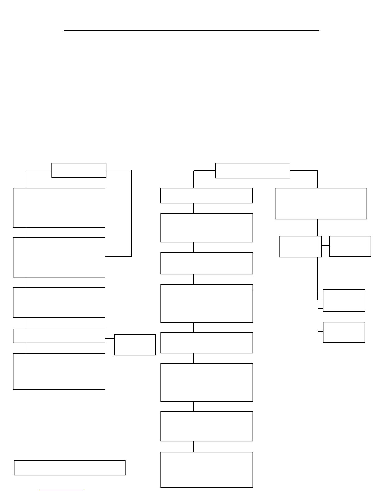
WIRELESS DRIVE-ALERT TROUBLESHOOTING TREE
Step 1 - Check to make sure the Power Light is on. If not, replace the internal 1A fuse, or send to Mier Products for repair.
Step 2 - Make sure the Control Panel is mounted in an above ground area where its antenna can receive a good signal from
the Sensor/Transmitter, and make sure the Sensor/Transmitter is in a position free where it can send a signal freely.
Make sure there are no large metal objects, mirrors, aluminum siding, etc. between the Control Panel and the Sensor/
Transmitter. There is a “continuous on” or “test” switch inside the transmitter to help you test signal strength.
Step 3 - Check to make sure all address codes inside the Control Panel match the address codes in the Sensor/Transmitter
Enclosure.
Step 4 - If installing a DA-605P, make sure the address codes in the small DA-066 mounted on the side of the Control Panel
match the address codes in the Chimes.
Step 5 - If installing a DA-605P, make sure there are no large metal objects, mirrors, appliances, etc. between the Control Panel
and the Chimes
False Alarms
Check the sensor/transmitter
placement - 60’ (min) away from
the street, power/phone lines.
Move sensor or reduce
sensitivity.
OK
Check the sensor/transmitter
placement to make sure it is
mounted securely, and not in a
tree if a DA-610TO (this is ok is
using a DA-611TO).
OK
Check the sensor/transmitter to
make sure it is not on the same
address code as a system at a
neighbor’s home.
OK
Remove all accessory wires from
the terminal block.
Still Not Fixes
Call Mier Products’ Free Tech
Support. They will work with you
and might recommend returning
the system to Mier Products for
diagnosis and repair.
ExistingNew
Accessory
Defective
Panel is quiet:
replace the
accessory
No Detection or
Intermittent Detection
Check the batteries, Power is
ON, TX_TEST is OFF/SW10
OK
Check sensor/transmitter
sensitivity at or near MAX on
the Sensitivity Adjustment in the
lower right corner
OK
Check sensor/transmitter
and Control Panel address
codes to make sure they match
OK
Check for metal obstructions,
sensor/xmitter 5’ MAX from 10’
drive edge, vehicle does not
pass between transmitter &
receiver
OK
If using more than one sensor/
transmitter, make sure they are
more than 20’ apart
OK
Check that VALID XMSN and
ALERT LEDs come on in the
Control Panel when a detection
and transmission was to occur.
Note: listen for a Relay “click.”
ExistingNew
Check POWER and LO BATT
LEDs on the control panel. If no
POWER LED replace the fuse.
If LO BATT replace the batteries.
Trigger sensor
by passing a
steel tool by it
Alert Sounds or
Relay Clicks
Return to Mier
Products for
Repair
No Alert but
Relay Clicks
Flip Whistle
Switch 25
times and retry
Still no Alert
Return to Mier
Products for
Repair
No Alert or
Relay Click
Tech Support: 800-473-0213 x 107
OK
If using a long-range reception
antenna, check connections and
orientation (vertical and short
end pointing toward transmitter).
Still Not Fixes
Call Mier Products’ Free Tech
Support. They will work with you
and might recommend returning
the system to Mier Products for
diagnosis and repair.
 Loading...