

Mielta M1 User Manual

GLONASS/GPS Tracker
MIELTA M1
(ТНА-1803-01)
User manual
Firmware version 2.7.0
Last modified 18.10.2018
Tambov 2018

MIELTA M1
Table of content
Table of content ................................................................................................... 2
1. Description ................................................................................................... 4
2. Technical characteristics .............................................................................. 5
3. General information ..................................................................................... 6
3.1 Power ................................................................................................... 6
3.2 Configuration ....................................................................................... 6
3.3 Communication .................................................................................... 6
3.4 Indication ............................................................................................. 8
3.5 Universal ports ..................................................................................... 9
3.6 Digital interfaces ................................................................................ 10
5. Functionality .............................................................................................. 11
4.1 Communication .................................................................................... 11
4.2 Unloading of the track to the server and traffic consumption .............. 11
4.3 Unloading track points to multiple servers ........................................... 12
4.4 Time synchronization ........................................................................... 12
4.5 Registration of track points .................................................................. 13
4.6 Filtering spurious emissions GPS coordinates ....................................... 14
4.7 Power-saving modes ............................................................................ 14
4.8 How to configure settings for Tracker .................................................. 15
4.9 Bluetooth access point ......................................................................... 16
4.10 Work with a Bluetooth headset .......................................................... 17
4.11 Digital sensors .................................................................................... 17
4.12 Work with the system display Mielta .................................................. 17
4.13 Working with FLS Autosensor ............................................................. 18
4.14 Working with ZET7012 pressure sensor .............................................. 18
4.15 Driver identification ............................................................................ 18
4.16 Manual control of discrete output ...................................................... 18
4.17 Discrete input ..................................................................................... 18
4.18 Alarm button ...................................................................................... 19
4.19 Odometer ........................................................................................... 19
2

MIELTA M1
4.20 Diagnostics ......................................................................................... 19
5 Software update ......................................................................................... 19
6 Installation ................................................................................................. 20
Annex 1 ................................................................................................................ 22
General purpose commands ...................................................................... 22
Commands set/get ..................................................................................... 25
Diagnostic commands ................................................................................ 44
Additional parameter data ......................................................................... 49
List of supported devices and protocols ..................................................... 50
3

MIELTA M1
1. Description
Tracker MIELTA M1 is focused on simple and economical solutions in the field of
monitoring in transport. M1 has compact dimensions, low weight and is equipped with
the most necessary interfaces for working with peripheral devices. The terminal is used
for collecting, processing, storing and transmitting information on mobile and stationary
objects of control. In combination with additional sensors it is possible to monitor fuel
consumption, activity of executive devices, vehicle parameters, driver identification and
much more. The terminal is adapted for power supply in any automotive on-board
network, has built-in antennas for easy installation.
4

MIELTA M1
Power supply
5 – 36 V protection from surges, reverse polarity
protection, PTC fuse.
Power consumption
1 W
Battery
No
Universal ports
2 ports
Analog input mode: DC 0-36 V, input resistance 30 kOhm,
10 bit ADC;
Discrete input mode: active level - 0V, internal pullup 3.3
V, input resistance 20 kOhm, frequency up to 40 kHz,
counter up to 1000000;
Discrete output mode: open collector, DC current up to
200 mA, self-induction protection.
Аccelerometer
Internal, 8G
1-wire
Internal, up to 8 devices
RS485
Internal, up to 8 devices
USB 2.0
Конфигурирование, прошивка, передача данных,
питание
Navigation
GLONASS, GPS, -166 dBm, internal patch antenna 25х25
mm
GSM-antenna
Internal, 900/1800 MHz
Bluetooth
Bluetooth 3.0, configuration, firmware update, data
transmission
Memory
4 Mb, 10000 points
SIM-card
1 pcs, micro-SIM
Multiserver
data transmission
3 server
Protocol
Wialon IPS 1.1, IPS 2.0, binary
Ingress Protection Rating
IP44
Operation temperature
-40 to +85 °С, humidity 98% at a temperature of 25 °С,
without dew.
Averall dimensions
49 х 64 х 17 mm
Weight
60 g
2. Technical characteristics
5

MIELTA M1
3. General information
3.1 Power
Tracker is designed for use in automotive on-board system voltage 12/24V, or from
USB adapter 5V 1A. When powered from on-board network has the ability to control the
discharge of the on-board battery and if necessary go into power saver mode before the
appearance of certain conditions depending on the configuration. Modern circuit solutions
enable the Terminal to work consistently in the range of supply voltage from 5 to 36 volts.
M1 has built-in protection against overvoltage, as well as pulse jamming.
3.2 Configuration
The Tracker has a set of commands to configure settings that control the State and
display information (see annex 1). The work can be carried out via the USB port (configurator
utility), via SMS, the TCP commands from the server monitoring (GPRS), as well as Bluetooth
(using Android-Configurator on the mobile device).
Default access password - 12345. If necessary, you can replace the password. If
you lose your password to regain access to the device is possible by contacting technical
support MIELTA.
3.3 Communication
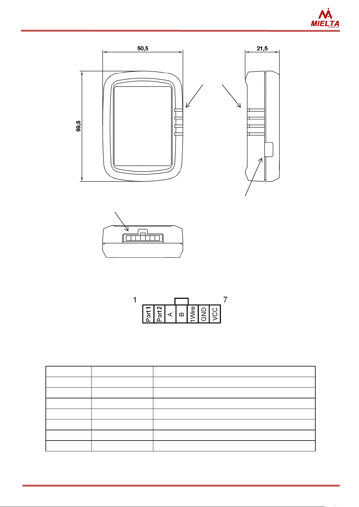
The Tracker has a USB connector for connecting to a personal computer and is used
to supply, configure and update software. Micro-Fit 3.0 connector is used to connect the
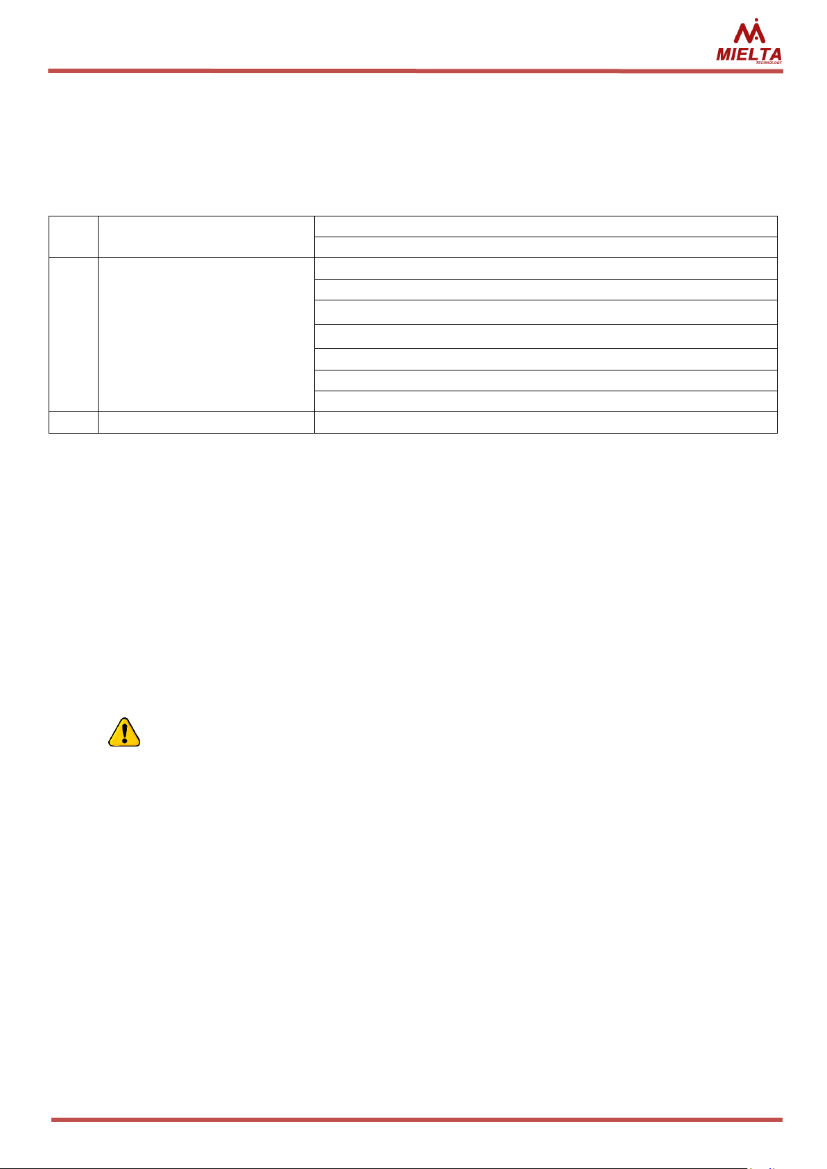
main power supply and peripherals. On the reverse side there is a schematic representation
of the plug-in contacts (Figure 2). Before placing it in your site, you must install a SIM card.
For this purpose it is necessary to unscrew the bottom cover of the Tracker, which is
attached with four screws. To protect against unauthorized access, the case is sealed up by a
sticker.
6
MIELTA M1
Номер
Обозначение
Description
1
Port1
Universal port 1
2
Port2
Universal port 2
3
A
RS-485 line А
4
B
RS-485 line B
5
1Wire
1-Wire
6
GND
Power ground
7
VCC
Power DC 5 – 36 V
Figure 2. Peripheral Micro-Fit connector
Pcture 1. M1 exterior
Interface
connector
LED indicators
USB 2.0
Table 1. Peripheral Micro-Fit connector piouts.
7

MIELTA M1
LED
Function
LED switched
on
Blinking slow
Blinking fast
Blinked once
Green
Power on
External power
No External power,
powered from USB
Black box
clearing
Track point
saving
Yellow
GLONASS/
GPS
Coordinates
are defined
Unstable GLONASS/
GPS signal
Time is not
synchronized
-
Blue
GSM
Registered in
mobile
network
Problems with
regsitration or SIM
card
Regsitration in
network
-
Red
Server
Connected to
Server
Problems connecting
to server
Activation of
GPRS-session,
connection to
the server
Sending data
to the server
3.4 Indication
On the front panel of the Tracker are 4 LEDs: green, yellow, blue, red (see table 2).
Table 2. Display during normal operation
Combination:
- All LEDs are switched on – normal work;
- Green blinking slow, red switched on – disaster recovery mode;
- Green led blinks one time in 10 seconds, other switched off – power saving mode;
- Blue and red LEDs blinked alternately – process of renovation.
In the display sequence:
1. Successful launch:
- Red (bootloader);
- turns off red, green (successful launch program);
- connecting to the GSM and the server.
2. Bad start:
- Red;
- reboot.
3. A bad start after you change the main program:
- red for 30 seconds;
- rebooting, several times trying to download;
- try to restore a previous version;
- normal start of the restored version of the program.
4. Power saving mode:
- light up quickly the two extreme, then two central – sleep mode.
8
MIELTA M1
1
Analog input
Voltage measurement, 0 – 36 V
Ignition signal control
2
Discrete input
Frequency measurement, 1 Hz – 40 kHz
Low frequency measurement, 0.1 Hz – 40.0 Hz
Counter, front edge, 0 – 999999
Counter, back edge, 0 – 999999
Discrete signal, 0/1
Encoder (Port1 + Port2), 0 - 999999, increment, decrement
Alarm button, 0/1, track point saving
3
Discrete output
0/1, i-button key activation
3.5 Universal ports
Universal ports Tracker can operate independently in the following modes (see table
3).
Table 3. Unversal ports modes
The analog input is designed for voltage measurement and registration of slowly
changing signals. Measurement of signal level occurs 20 times per second. The data
smoothing algorithm is applied.
When you activate the ignition control function, you can select the signal source is
one of universal ports either power network. In this mode, the Tracker monitors voltage and
modifies the Boolean value of the "IGN" when passing through the established threshold
voltages.
Binary input, designed to work with sensors and signal sources open collector type.
High signal level limited voltage 36 V, low level should be no more than 1 V from GND. The
Tracker has an internal pullup to + 3.3 v.
In some cases, to improve anti-jamming and ensure a minimum load current of
a frequency output of the external appliance, you must be connected pullup
resistors with nominal 4.7-10 kOhm between the signal wire and power plus (no
more than 36 V).
Tracker has two modes of frequency measurement - high and low, two modes of
counting pulses with synchronization on the front and the recession signal, as well as logical
status mode entry (entry by the mass closure gives «1»).
Encoder mode uses two ports simultaneously and can keep counting pulses from 0 to
999999 in two directions (increment, decrement). Used, for example, for compensation of
oscillating movements of flow sensors.
Digital output is built according to the scheme "open collector" and is intended for
control of actuating devices. The following operating modes: manual mode (switch output
status on the team) and identification mode (change status to detect the iButton keys/RFID
cards out of the allowed range).
9
MIELTA M1
Length of the line
The number of
devices on the bus
The type of cable used
Topology
Up to 5 m
Up to 8 pcs
Любой
Free
Up to 20 m
Up to 8 pcs
2x22(20) AWG
UTP Cat. 3-5e
Bus with patches
up to 0,5 m
Up to 50 m
Up to 8 pcs
Only UTP, FTP Cat. 3-5e
Bus only
Length of the line
The number of
devices on the bus
The type of cable used
Topology
Up to 20 m
Up to 8 pcs
2x22(20) AWG
UTP Cat. 3-5e
Bus with patches
up to 5 m
Up to 100 m
Up to 8 pcs
Only FTP, STP, S/FTP Cat. 5-7
Bus with patches
up to 2 m
Before activating discrete output mode of universal port Tracker, disconnect
all external circuits connected to this port.
Before connecting the external circuit, make sure that the current universal
port in discrete mode will not exceed the maximum value of 200 mA.
3.6 Digital interfaces
Algorithm of working with digital sensors is built on traditional trackers MIELTA
scheme with virtual slots. In Tracker defined slots for each digital interface (eight for RS485
and eight for 1-Wire), each of which can be configured on any sensor supported by tracker.
The main advantage of this approach is flexibility, ease of configuration and the ability to
simultaneously support various protocols on a single interface. Configuring sensors can be
made during operation, do not interrupt the flow of data and does not require restarting.
Data can be obtained immediately after the correct sensor settings (using Configurator, all
changes can be tracked in real time).
Featured network settings for peripheral devices 1-Wire and RS-485 are given in
tables 4 and 5.
Table 4. Featured 1-Wire network settings
Table 5. Recommended settings for the RS-485 network
With a bus length of more than 20 metres, you must use a terminating resistor
120 Ohm on the opposite end of the line from Tracker.
To ensure correct and safe operation of digital interfaces must combine mass
potentials of Tracker and connected devices, or negotiate signal using an optical
isolator.
10

MIELTA M1
5. Functionality
4.1 Communication
Tracker has combined communication module SIM868. On the PCB is installed microSIM card holder with hinged lid, for the installation it is necessary to open the case. Supports
hot swapping the SIM card without shutting down the power supply.
Built-in GSM modem works in the ranges 900/1800 Mhz, supports GPRS class B, multi
slot 12/10. To activate the GPRS access point settings are as follows:
access point name;
login;
password.
If GPRS-session is active, the Tracker starts the process of connecting to the
monitoring server. Simultaneous work with three different servers. To configure the
connection, use the following options:
Server address (possibly set up as an IP address, for example 193.193.165.165,
and the DNS name of the server, for example hosting.wialon.com, the
maximum length of the name is 63 characters for the main server and 47
characters for two additional servers);
the connection port, depending on the Protocol (for example, 21204);
the access password to the server, the maximum length is 15 characters;
communication protocol (Wialon IPS 1.1, 2.0 and Wialon IPS binary protocol
supported).
4.2 Unloading of the track to the server and traffic consumption
After successfully connecting to the servers Tracker starts unloading collected data
track from the built-in "black box". The M1's internal memory store up to 10000 records,
intended to send to each server and for unloading through the configurator. The number of
points to be sent to each server does not depend on the number of configured connections.
The order to unload of the messages and "black box" from newest to oldest. Tracker allows
you to unload up to 10 points in the package, no more than 1 kilobyte. When you add a new
server will be unloaded to 10000 previous entries, so if necessary, clean up the "black box".
The following modes of uploading data:
Quick. This type of unloading is the most uneconomical in terms of traffic,
however, allows you to track the object on the server with the minimum of
delay. If the connection to the server is active, the track point to the server is
unloaded immediately after registering the Tracker.
Batch. This type of discharge is a compromise between the consumption of
bandwidth and delay in unloading the current data on the server. This mode is
specified by setting the maximum allowable delay unloading data. That is, a
package to send to the server is formed or when a maximum delay time of
11

MIELTA M1
departure of the previous package, or if the number of records in the black box
is greater than the maximum possible number of points in the package. In other
words, if the black box is empty, the Tracker is waiting for the timeout to allow
sending the next packet, and if the black box records accumulated, then the
Tracker sends data packets without delays until it unloads all the records from
the black mailbox.
According to the schedule. This mode provides for economical unloading track.
To do this, specify the period during which the discharge is the accumulation of
data. Accumulation mode data connections with approved servers and GPRSsession inactive. Over time accumulate data Tracker connects to the approved
to operate servers and uploads data. After sending all black box data Tracker
again terminates connections and accumulates data during the period of
discharge. Data accumulation mode remotely Tracker is available only for SMS
commands.
Unloading track modes are on a home network and roaming. Here it is worth noting
that the more track points will be sent in the package, the lower the overhead of packet
headers and less traffic consumption. To send data Tracker uses TCP connections.
When you configure the modes and conditions registration track points should be
borne in mind that the Tracker includes support for permanent connection to servers (keepalive) connection was lost on timeout. If the timeout time (3 minutes) you have an active
connection to the server was not sending data packets, then the server is sent to the ping
package. This reduces the costs associated with the disconnects and reconnects to the
server, but still consumes bandwidth.
4.3 Unloading track points to multiple servers
The Tracker has the ability to work with multiple monitoring servers simultaneously.
For each server, you can specify any supported in this version of the Protocol. When
configuring the connection sets connection activity indicates an IP or domain name, port and
Protocol for transferring data. Password authorization on the server and the mode of
unloading points is defined globally for all connections after sending a password to access
tracker from one server appears automatically access from other active servers, so if
necessary after the completion of the the remote works with the Sun Tracker to send click
logout. All posts by user actions are sent simultaneously on all servers that are specified in
the settings of the Tracker. The maximum number of entries does not depend on the
number of configured connections-entry points is executed simultaneously for all
connections and unloading through the configurator. If a server is unavailable, then slowed
down unloading points on the available servers.
accurate time. Tracker allows you to synchronize time in two ways: to seek the exact time
4.4 Time synchronization
After power Tracker, you must synchronize the system time with the source of
12

MIELTA M1
with the base stations of cellular operator or get from GPS/GLONASS satellites. Until the
time Tracker is not synchronized, the registration points of the track is prohibited. Sync on
base stations immediately after power-up lets you ensure that data with connected sensors,
even in the absence of sustained signal reception with GPS/GLONASS satellites. It is worth
noting that not all mobile operators support this feature.
Every day when you change the date system time check is received over time from
navigation satellites. If vehicle is stationary for a long time with poor signal reception from
satellites (garage), then perhaps the clock error accumulation system time on the monitor
server in this case will send a message to "WARN: RTC CLOCK".
4.5 Registration of track points
Register Tracker track points being in one of three modes:
stop;
parking;
movement.
After power and time synchronization Tracker allows the registration points of the
track and goes into "stop" mode. In this mode there are two settings:
Period of registration points. Sets the time interval between registration
points track points.
A time of transition in mode of "parking". Sets the maximum time spent in
"pause" mode, after which the Tracker goes “parking”. The main difference
between these modes is that parked its associated configuration, you can
enable power saving mode, which will be described below.
In the "parking" you can configure the registration period points. When you register
the beginning of movement "stop" mode or "parking" becomes "movement". For flexible
adjustment of registration points during movement, there are two profile settings for low
and high speed. First you need to specify boundary velocity ranges, separating low and high
speed. Such partitioning enables you to, for example, to specify different settings for traffic
in the city and on the highway. For each profile contains the following settings:
Distance. Sets the maximum distance relative to the previous registered point
track.
Angle. Sets the maximum change of direction relative to the previous
exceeding the maximum permissible speed. To configure logging points to exceed the
stipulated two settings:
registered point track.
It's time. Sets the maximum time between registration points track points.
For the "movement" mode is also implemented registration of track points on
Exceeding the speed limit. Sets the maximum permissible speed of an object,
by exceeding which the track point.
The increment speed in excess of. Sets the interval register track points for
speeding.
13

MIELTA M1
There is a possibility of formation of track points to exceed the threshold values for
the custom acceleration in units of G acting on the Tracker. Thus, there is a possibility of
fixing cases sharp acceleration or braking the vehicle. In repose to the Tracker operates free
fall acceleration 1 G.
Additionally there is the possibility to adjust the registration point of the track when
the status of the ignition.
4.6 Filtering spurious emissions GPS coordinates
In order to prevent the registration of coordinates with low accuracy in Tracker "GPS
filter" is implemented. This filter has the following settings::
Maximum HDOP;
The minimum number of satellites.
To filter the "false travel" and "stars" on parking included filters and acceleration
sensor filter by ignition. Filters can be independently enabled and disabled. If both filters are
activated and acceleration sensor registers movement start and ignition while inactive (for
example, during the evacuation of the vehicle), the Tracker will register the track. To control
the ignition can be used one of universal ports mode, either supply voltage Tracker. For each
source there is hysteresis. To filter the "stars" on parking in areas with unstable satellite
signal you should disable transmission of coordinates on parking removal appropriate check
box in the Configurator or using the console command.
4.7 Power-saving modes
In Tracker implemented three energy mode:
Main mode. In this mode, the Tracker logs track points and produces data
submission in accordance with predefined settings.
The power saving mode. Mode is designed to conserve battery power on
parking, excluding the data loss. That is, registration data from sensors and
GPS-receiver does not stop. And turns off to save power GSM-module and is
included once per hour to 15 minutes for unloading of the track. If it is
prohibited to unload in roaming, GPRS session is not activated, but left in an
enabled state module and the Tracker is ready, if necessary, to perform the
incoming SMS commands. To enable and disable features you can configure
"allow power saving mode on parking." If the mode is enabled, the Tracker
navigates to it immediately after switching to "parking".
Sleep mode. Mode is intended for long-term parking. Sleep mode periodically
Tracker keeps track of the value of the supply voltage, the rest of the
functionality is unavailable. For cases the power supply of the Tracker directly
from the battery of the vehicle and, if the assumed long breaks between
journeys, it is recommended that you enable the setting "enable sleep mode
on parking" for operation from external power. Here you can set two
14

MIELTA M1
Command
Ansver
pwd 12345
Welcome! User logged in
set apn 1 internet.beeline.ru
ok
set loginapn 1 beeline
ok
set pwdapn 1 beeline
ok
set phone 1 79601234567
ok
rebootall
Command
Ansver
thresholds: voltage of “sleep mode" and exit voltage of the mode. That is, here
the Tracker also tracks the change in voltage (at the got engine voltage higher
than off).
4.8 How to configure settings for Tracker
Tracker configuration is done using the text console commands. To access the
Tracker you must enter a password. In cases of loss of password, you can enter the master
password. Address in technical support of MIELTA. Master password has a limited validity
period.
Several ways to customize the Tracker:
• TCP commands;
• SMS commands;
• Windows configurator utility by USB;
• Android configurator utility by Bluetooth.
Configuring TCP or SMS comes directly sending the text console commands to the
Tracker. It is possible to send multiple commands in a single message, with commands
written in execution order and are delimited by a semicolon. A full list of commands is given
in annex 1.
Working with Mielta Tracker in console mode begin with user authorization pwd
command. All commands except for pwd and logout last line return OK or ERR. OK indicates
that the command completed successfully, ERR means that an error occurred while
executing the command or command is entered incorrectly. In the Tracker, there are several
users, each of which independently authorization is required: 1. Phone (SMS) 1; 2. Phone 2
(SMS); 3. Phone (SMS) 3; 4. Phone (SMS) 4; 5. USB (command line); 6. Bluetooth; 7. TCP
(server monitoring). Allowed simultaneous work with multiple Tracker users. A list of phone
numbers from which allowed sending commands to the Tracker, you can get phone, allow
new phone number-set phone.
After entering the password, Access opens automatically closes after 30 minutes of
inactivity or the corresponding command.
Table 6. Tracker sample, configure connection parameters:
Table 7. For an example of configuring sensors:
15

MIELTA M1
pwd 12345
Welcome! User logged in
set sensor R4.1 LLS Fuel 1 1 3
ok
set sensor OW1 DS1820 Temp 1 1 987654321
ok
logout
Good-bye! User logged out
To work on USB or Bluetooth designed Windows and Android configurator utility.
When working through the Configurator also possible sensor tracking and statuses in real
time. When working with Android-configurator to start searches for available Bluetooth
devices.
Once the desired access point Bluetooth connection PIN code is requested, then the
Configurator prompts you to enter a password to access the device. After entering the
correct password Configurator has access to Tracker.
Tracker in the Windows operating system is defined as a virtual COM port. By clicking
the "device selection" in the Configurator runs the search window, where you can view all
devices found trackers. After selecting one of them and enter a password to access the
connection occurs. To work with Windows-Configurator Additionally implements the
following functions:
• firmware update Tracker from a file;
• unloading of the track records of the black box in a file, it is possible to unload
already sent points;
• import/export of all settings in the file Tracker.
4.9 Bluetooth access point
To configure the access point provides the following options for:
PIN. You need to initialize the connection via Bluetooth.
The name of the access point. Is set to identify the Tracker when you search
for available Bluetooth devices. By default, the name is defined as a numerical
value device IMEI.
Implemented multiple modes of operation:
Disabled. Bluetooth access point is unavailable.
Enabled until you restart. Activates the access point until you restart Tracker.
When power is turned on. The access point is activated every time when you
disconnect and external supply voltage (even if you are reconnecting Tracker
continues to work from the built-in battery). Access point after reconnecting
the power active 15 minutes, and if during that time was not Bluetooth
connection after this time is disabled.
Always on. Bluetooth access point always available.
Speakerphone. Bluetooth is used to connect to the headset for voice
communication (see section 4.10).
16
 Loading...