

Page 1

Descriptive Technical
Documentation
- Model-dependent -
DTD no. 41-8000
Model(s): S 8310, S 8330, S 8340, S 8360,
S 8390, S 8510, S 8530, S 8540,
S 8560, S 8590, S 8510 UniQ,
S 8530 UniQ, S 8540 UniQ,
S 8560 UniQ, S 8590 UniQ, S 8710,
S 8730, S 8790, S 8930, S 8960
07.06.2013, US_am This information should not be duplicated or passed on without Miele approval. All rights reserved.
Page 2

Contents
General Information
A Warning and Safety Instructions
B Modification History
C Technical Data
Function Groups
010 Base
4 Service. . . . . . . . . . . . . . . . . . . . . . . . . . . . . . . . . . . . . . . . . . . . . 010-2
4.1 Caster (Dynamic Drive) Removal . . . . . . . . . . . . . . . . . . . . . . . . . 010-2
4.2 Parking Slot Removal. . . . . . . . . . . . . . . . . . . . . . . . . . . . . . . . . . . 010-2
4.3 Lighting Assembly Replacement (Uniq Only). . . . . . . . . . . . . . . . 010-3
020 Cover Frame
4 Service. . . . . . . . . . . . . . . . . . . . . . . . . . . . . . . . . . . . . . . . . . . . . 020-2
4.1 Bag Holder Replacement. . . . . . . . . . . . . . . . . . . . . . . . . . . . . . . . 020-2
4.2 Cover Frame Removal . . . . . . . . . . . . . . . . . . . . . . . . . . . . . . . . . . 020-3
030 Dust Compartment Lid
4 Service. . . . . . . . . . . . . . . . . . . . . . . . . . . . . . . . . . . . . . . . . . . . . 030-2
4.1 Accessory Compartment Lid Removal . . . . . . . . . . . . . . . . . . . . . 030-2
4.2 Dust Compartment Lid Removal. . . . . . . . . . . . . . . . . . . . . . . . . . 030-2
4.3 Dust Channel Assembly Removal . . . . . . . . . . . . . . . . . . . . . . . . 030-3
4.4 Bag Change Indicator Removal . . . . . . . . . . . . . . . . . . . . . . . . . . 030-4
4.5 Hinge Socket Wiring Harness Removal . . . . . . . . . . . . . . . . . . . . 030-4
040 Operating Unit
2 Function . . . . . . . . . . . . . . . . . . . . . . . . . . . . . . . . . . . . . . . . . . . 040-2
2.1 Operating Units: S 83xx to S 89xx . . . . . . . . . . . . . . . . . . . . . . . . 040-2
2.1.1 S 83xx Series . . . . . . . . . . . . . . . . . . . . . . . . . . . . . . . . . . . . . . . . . 040-2
2.1.2 S 85xx Series . . . . . . . . . . . . . . . . . . . . . . . . . . . . . . . . . . . . . . . . . 040-2
2.1.3 S 87xx Series . . . . . . . . . . . . . . . . . . . . . . . . . . . . . . . . . . . . . . . . . 040-3
2.1.4 S 89xx Series . . . . . . . . . . . . . . . . . . . . . . . . . . . . . . . . . . . . . . . . . 040-4
2.2 Automatic Suction Power Control . . . . . . . . . . . . . . . . . . . . . . . . . 040-5
3 Fault Repair . . . . . . . . . . . . . . . . . . . . . . . . . . . . . . . . . . . . . . . . 040-6
3.1 Motor Does Not React in the "Automatic" Setting or Always
Runs at High Speed . . . . . . . . . . . . . . . . . . . . . . . . . . . . . . . . . . . . 040-6
4 Service. . . . . . . . . . . . . . . . . . . . . . . . . . . . . . . . . . . . . . . . . . . . . 040-8
4.1 Operating Unit Removal. . . . . . . . . . . . . . . . . . . . . . . . . . . . . . . . . 040-8
Descriptive Technical Documentation
DTD no. 41-8000 1
07.06.2013, US_am This information should not be duplicated or passed on without Miele approval. All rights reserved.
Page 3

4.2 Electronic Board Removal . . . . . . . . . . . . . . . . . . . . . . . . . . . . . . . 040-9
4.3 On/Off Switch Removal . . . . . . . . . . . . . . . . . . . . . . . . . . . . . . . . . 040-10
4.4 Powerbrush Outlet Wiring Harness Removal. . . . . . . . . . . . . . . . 040-10
4.5 Park Switch Replacement (Model-Dependent) . . . . . . . . . . . . . . 040-10
050 Motor, Cord Reel
2 Function . . . . . . . . . . . . . . . . . . . . . . . . . . . . . . . . . . . . . . . . . . . 050-2
2.1 Thermal Protection Function . . . . . . . . . . . . . . . . . . . . . . . . . . . . . 050-2
3 Fault Repair . . . . . . . . . . . . . . . . . . . . . . . . . . . . . . . . . . . . . . . . 050-3
3.1 Suction Power Too Low . . . . . . . . . . . . . . . . . . . . . . . . . . . . . . . . . 050-3
3.2 Motor Does Not Run . . . . . . . . . . . . . . . . . . . . . . . . . . . . . . . . . . . 050-4
4 Service. . . . . . . . . . . . . . . . . . . . . . . . . . . . . . . . . . . . . . . . . . . . . 050-6
4.1 Motor/Cord Reel Cover Removal . . . . . . . . . . . . . . . . . . . . . . . . . 050-6
4.2 Motor Replacement . . . . . . . . . . . . . . . . . . . . . . . . . . . . . . . . . . . . 050-6
4.3 Cord Reel Replacement . . . . . . . . . . . . . . . . . . . . . . . . . . . . . . . . 050-7
4.4 Pre-Motor Filter Frame Removal . . . . . . . . . . . . . . . . . . . . . . . . . . 050-7
060 Suction Hose, Handle (S 83xx)
3 Fault Repair . . . . . . . . . . . . . . . . . . . . . . . . . . . . . . . . . . . . . . . . 060-2
3.1 LEDs in LED Handle Do Not Light . . . . . . . . . . . . . . . . . . . . . . . . 060-2
4 Service. . . . . . . . . . . . . . . . . . . . . . . . . . . . . . . . . . . . . . . . . . . . . 060-3
4.1 Telescopic Suction Hose Locking Piece Replacement . . . . . . . . 060-3
4.2 Pushbutton Replacement . . . . . . . . . . . . . . . . . . . . . . . . . . . . . . . 060-3
4.3 LED Handle Battery Replacement (Model-Dependent) . . . . . . . 060-4
061 Radio-Controlled Suction Hose (S 87xx)
3 Fault Repair . . . . . . . . . . . . . . . . . . . . . . . . . . . . . . . . . . . . . . . . 061-2
3.1 Radio-Controlled Handle Not Functioning . . . . . . . . . . . . . . . . . . 061-2
4 Service. . . . . . . . . . . . . . . . . . . . . . . . . . . . . . . . . . . . . . . . . . . . . 061-3
4.1 Battery in Radio-Controlled Handle Replacement (Model-
Dependent). . . . . . . . . . . . . . . . . . . . . . . . . . . . . . . . . . . . . . . . . . . 061-3
Descriptive Technical Documentation
2 DTD no. 41-8000
This information should not be duplicated or passed on without Miele approval. All rights reserved. 07.06.2013, US_am
Page 4

A Warning and Safety Instructions
1 General Information
All repairs should be performed by a trained technician in strict accordance with
national, state and local codes. Any repairs or maintenance performed by
unqualified personnel could be dangerous.
When servicing, modifying, testing or maintaining appliances, all applicable laws,
regulations and accident prevention guidelines must be observed.
All regulations of the appropriate utility supply companies and standards relating
to safety (not limited to electrical safety) are to be complied with.
Before starting any service work, disconnect the vacuum cleaner from power.
Even with the vacuum cleaner switched off, voltage may be applied to some
components.
After work has been completed, a visual as well as an operational check should
always be performed.
Descriptive Technical Documentation
DTD no. 41-8000 A-1
07.06.2013, US_am This information should not be duplicated or passed on without Miele approval. All rights reserved.
Page 5

B Modification History
x
When? Who? What?
20.04.2012 Reinhard Bremehr – Initial compilation
Descriptive Technical Documentation
DTD no. 41-8000 B-1
07.06.2013, US_am This information should not be duplicated or passed on without Miele approval. All rights reserved.
Page 6
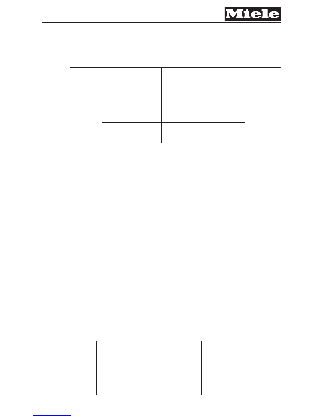
C Technical Data
Model Operating controls Motor/Exhaust filter Version
S 8 3: +/- foot switches 1: Power + AirClean 0
5: +/- foot switch with Automatic 2: Power + Active AirClean
7: Radio-controlled handle 3: Power + Active HEPA
9: Electro handle 4: Efficiency + AirClean
5: Efficiency + Active AirClean
6: Efficiency + Active HEPA 7
7: Silence + AirClean
8: Silence + Active AirClean
9: Silence + Active HEPA
Table 1
Descriptions of various features
Easylock
Telescopic suction hose that can be
secured with a special clip.
Thermo indicator
Indicator light that lights up when the
thermal motor protection has tripped
(motor will restart after it has cooled).
Park System
Suction hose can be stored in the rear
slot on the vacuum during short breaks.
Dynamic Drive Shock-mounted rubber casters.
Silence Plus
Additional plastic casing for the motor
plus AirTeQ floor nozzle attachment.
Table 2: Descriptions of Various Features
Motor versions
Power 2200 W High-power motor
Efficiency 1200 W Economical motor
Silence 1200 W
Especially quiet motor (71 dB(A) re 1pW in
combination with the AirTeQ floor nozzle and an
AAC (Active AirClean) filter
Table 3
Model
S 8380 Cat &
Dog
S 8390
Calima
S 8390 Kona
S 8390
HomeCare
S 8590 Alize S 8590 Marin S 8990 UniQ
Color Koi orange
Canary
yellow
Obsidian
black
Mango red Ivory white
Navy blue
metallic
Mahogany
brown
metallic
Powerful
Vortex
Motor™,
manufactured
by Miele
Low noise,
1200-watt
Low noise,
1200-watt
Low noise,
1200-watt
Low noise,
1200-watt
Low noise,
1200-watt
Low noise,
1200-watt
Low noise,
1200-watt
Descriptive Technical Documentation
DTD no. 41-8000 C-1
07.06.2013, US_am This information should not be duplicated or passed on without Miele approval. All rights reserved.
Page 7
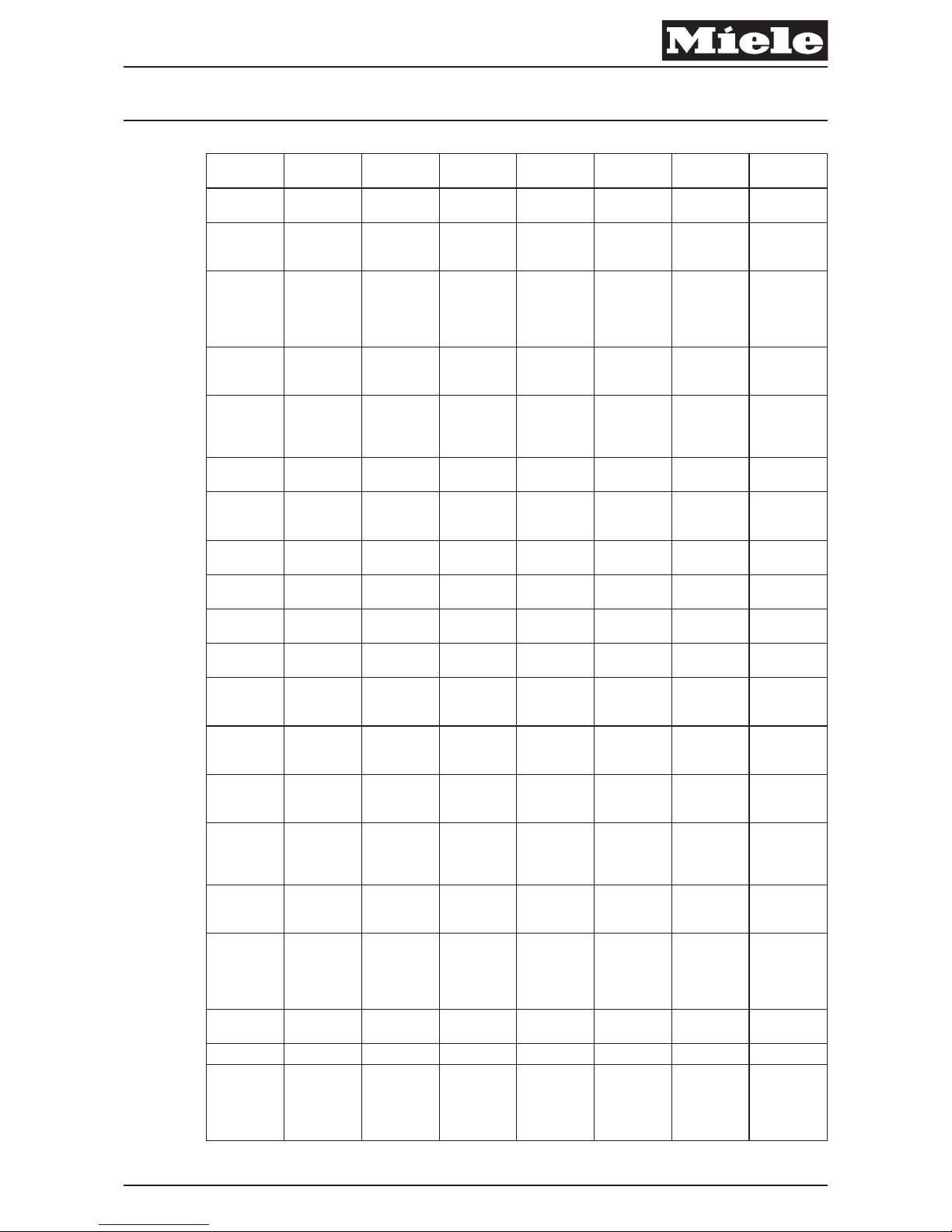
Model
S 8380 Cat &
Dog
S 8390
Calima
S 8390 Kona
S 8390
HomeCare
S 8590 Alize S 8590 Marin S 8990 UniQ
Power
adjustment
+/- foot switch +/- foot switch +/- foot switch +/- foot switch +/- foot switch +/- foot switch
Handle
controls
Number of
power
settings
6 6 6 6 6 6 6
Motor
protection
function with
safety shutoff
Yes Yes Yes Yes Yes Yes Yes
Motor
protection
indicator
No No No No Yes Yes Yes
AirClean
Sealed
System™
construction
Yes Yes Yes Yes Yes Yes Yes
AirClean
FilterBag™
Type G/N,
4.76 quart
Type G/N,
4.76 quart
Type G/N,
4.76 quart
Type G/N,
4.76 quart
Type G/N,
4.76 quart
Type G/N,
4.76 quart
Type G/N,
4.76 quart
FilterBag™
change
indicator
Yes Yes Yes Yes Yes Yes Yes
Air Clean
filter
Optional Optional Optional Optional Optional Optional Optional
Active Air
Clean filter
Standard Optional Optional Optional Optional Optional Optional
Active HEPA
filter
Optional Optional Standard Standard Standard Standard Standard
Pre-motor
filter
Yes Yes Yes Yes Yes Yes Yes
Filter
replacement
indicator
No No No No Yes Yes Yes
Lightweight
skeleton
construction
Yes Yes Yes Yes Yes Yes Yes
Rear park
system for
short breaks
Yes Yes Yes Yes Yes Yes Yes
Automatic
standby
switch in rear
park position
No No No No Yes Yes Yes
Side park
system for
storage
Yes Yes Yes Yes Yes Yes Illuminated
Long
electrical cord
with
automatic
rewind
One-touch One-touch One-touch One-touch One-touch One-touch One-touch
Cleaning
radius
33' 36' 36' 36' 36' 36' 36'
Bumper strip Yes Yes Yes Yes Yes Yes Velvet
360° caster
wheels for
high
maneuverability
Yes Yes Yes Yes
Dynamic
Drive
Yes Yes
Descriptive Technical Documentation
C-2 DTD no. 41-8000
This information should not be duplicated or passed on without Miele approval. All rights reserved. 07.06.2013, US_am
Page 8
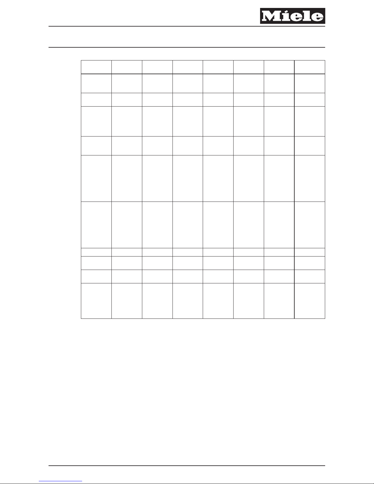
Model
S 8380 Cat &
Dog
S 8390
Calima
S 8390 Kona
S 8390
HomeCare
S 8590 Alize S 8590 Marin S 8990 UniQ
Telescopic
stainlesssteel wand
Yes Yes Yes Yes Yes Yes Yes
Durable hose
Straight
suction
Straight
suction
Straight
suction
Electric Electric Electric Electric
Deluxe
handle grip
with
electrobrush
control
No No Yes Yes Yes Yes Yes
Suction
controls via
handle
No No No No No No Yes
Standard
floor tool
Handheld
Turbobrush
(STB101),
ElectroPlus
(SEB 228),
Parquet
Twister (SBB
300-3)
TurboComfort
(STB 205-3),
Parquet
Twister (SBB
300-3)
ElectroPlus
(SEB 228),
Parquet
Twister (SBB
300-3)
Classic
Combination
floor tool
(SBD 285-3)
AirTeQ
Combination
floor tool
(SBD 650-3)
Parquet
Twister (SBB
300-3)
Parquet
Twister (SBB
300-3),
ElectroPremi-
um (SEB
236)
Optional
electrobrushes
ElectroComfort (SEB 217-
3),
ElectroPlus
(SEB 228),
ElectroPremi-
um (SEB
236)
ElectroComf-
ort (SEB 217-
3),
ElectroPlus
(SEB 228),
ElectroPremi-
um (SEB
236)
Dusting brush Integrated Integrated Integrated Integrated Integrated Integrated Integrated
Upholstery
tool
Integrated Integrated Integrated Integrated Integrated Integrated Integrated
Crevice
nozzle
Integrated Integrated Integrated Integrated Integrated Integrated Integrated
Additional
accessories
Flexible
crevice
nozzle (SFD
20), universal
brush (SUB
20)
Spotlight
handle
Table 4: Technical Data
Descriptive Technical Documentation
DTD no. 41-8000 C-3
07.06.2013, US_am This information should not be duplicated or passed on without Miele approval. All rights reserved.
Page 9
010 Base
Descriptive Technical Documentation
DTD no. 41-8000 010-1
07.06.2013, US_am This information should not be duplicated or passed on without Miele approval. All rights reserved.
Page 10
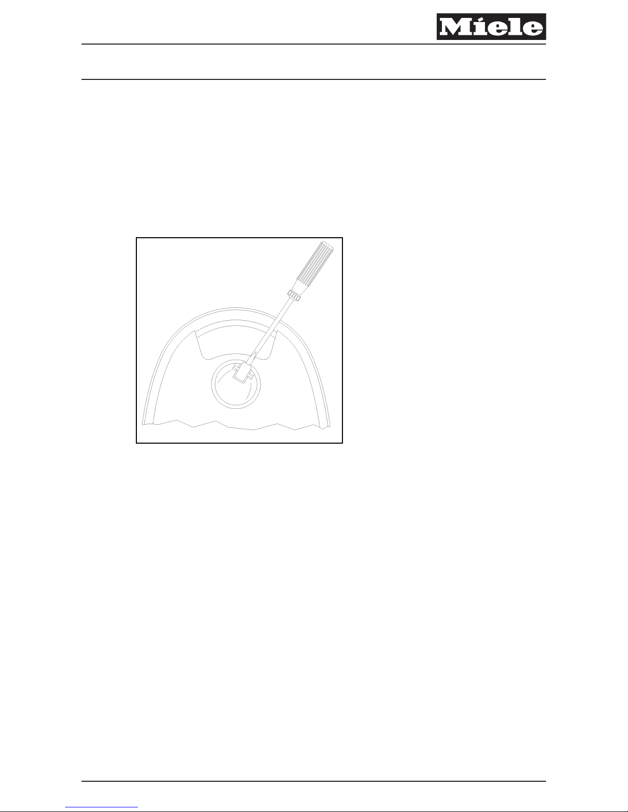
4 Service
4.1 Caster (Dynamic Drive) Removal
A Using a flathead screwdriver, lever the wheel out of the caster, then lever the
caster out of the base (010 Fig. 1).
A To reinstall, press the caster back into the base until it clicks, then press the
wheel into the caster until it clicks.
x
Fig. 1: Caster Removal
4.2 Parking Slot Removal
A Cover Frame Removal, 020 4.2.
A Remove the T20 screw securing the appropriate parking slot (010 Fig. 2, Pos.
3).
Descriptive Technical Documentation
010-2 DTD no. 41-8000
This information should not be duplicated or passed on without Miele approval. All rights reserved. 07.06.2013, US_am
Page 11
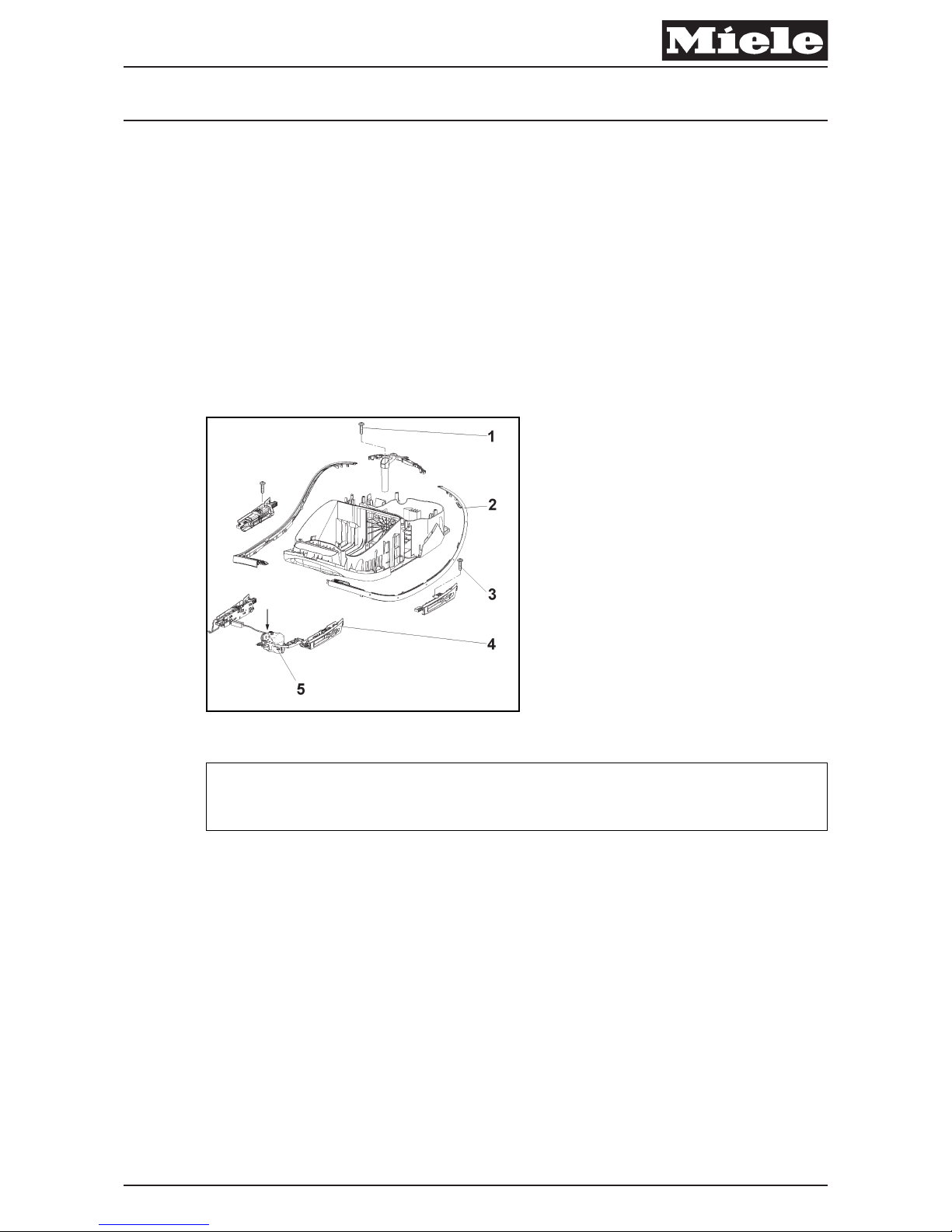
4.3 Lighting Assembly Replacement (Uniq Only)
A Cover Frame Removal, 020 4.2.
A Remove the bumper strip (010 Fig. 2, Pos. 2).
A Remove the T20 screws securing the parking slots on either side of the base
(010 Fig. 2, Pos. 3).
A Disconnect the lighting assembly wiring harness (010 Fig. 2, Pos. 5) from the
electronic board.
A Remove each parking slot together with the lighting assembly (010 Fig. 2,
Pos. 4).
x
Fig. 2
Note
The lighting assembly can only be replaced in its entirety.
A Reinstall by following these instructions in reverse order.
Descriptive Technical Documentation
DTD no. 41-8000 010-3
07.06.2013, US_am This information should not be duplicated or passed on without Miele approval. All rights reserved.
Page 12
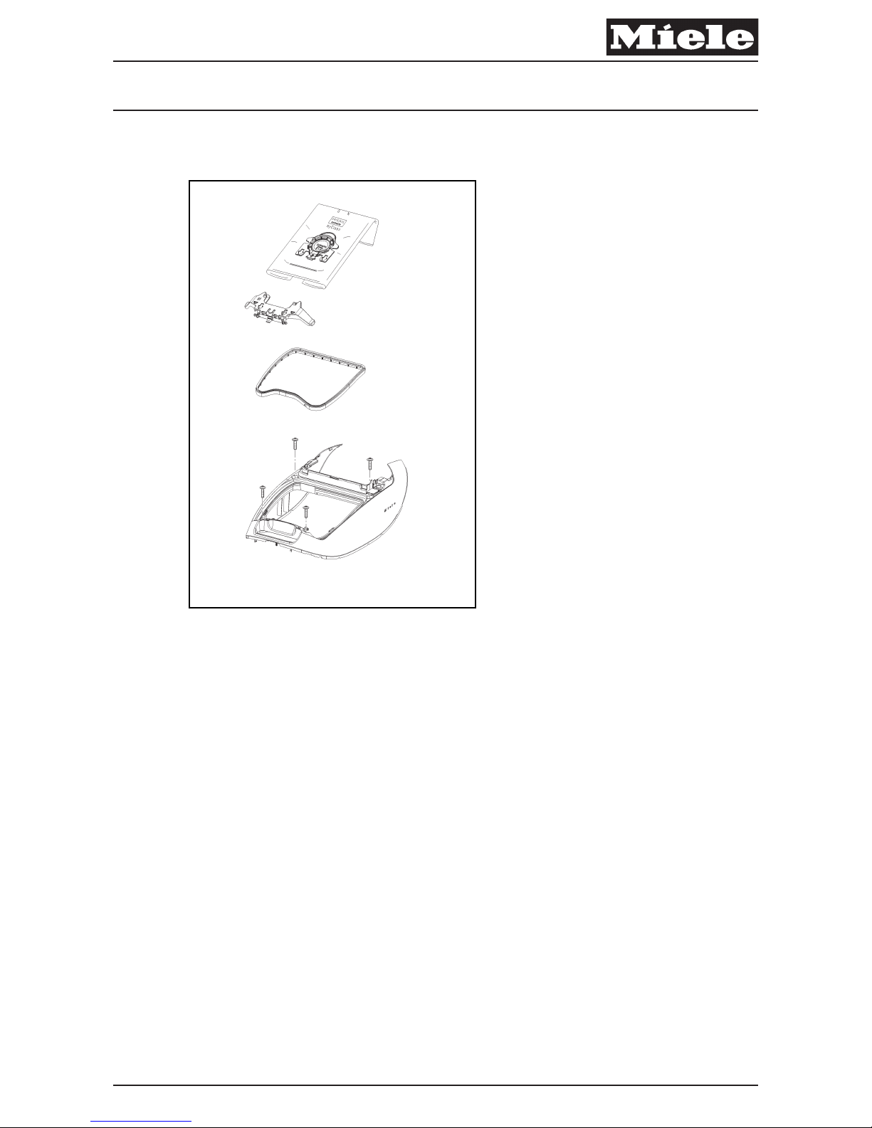
020 Cover Frame
x
Descriptive Technical Documentation
DTD no. 41-8000 020-1
07.06.2013, US_am This information should not be duplicated or passed on without Miele approval. All rights reserved.
Page 13
4 Service
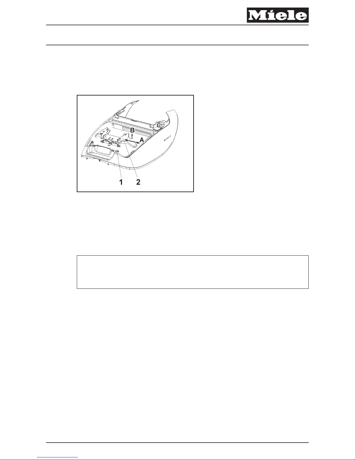
4.1 Bag Holder Replacement
x
Fig. 1: Bag Holder
A Open the dust compartment lid.
A Take out the dustbag.
A Hold the bag holder (020 Fig. 1, Pos. 2) with one hand and carefully unsnap it
from the hinge pins (020 Fig. 1, Pos. 1).
x
Warning!
Only do this procedure by hand. Using a screwdriver or other tool will break the
bag holder.
Descriptive Technical Documentation
020-2 DTD no. 41-8000
This information should not be duplicated or passed on without Miele approval. All rights reserved. 07.06.2013, US_am
Page 14
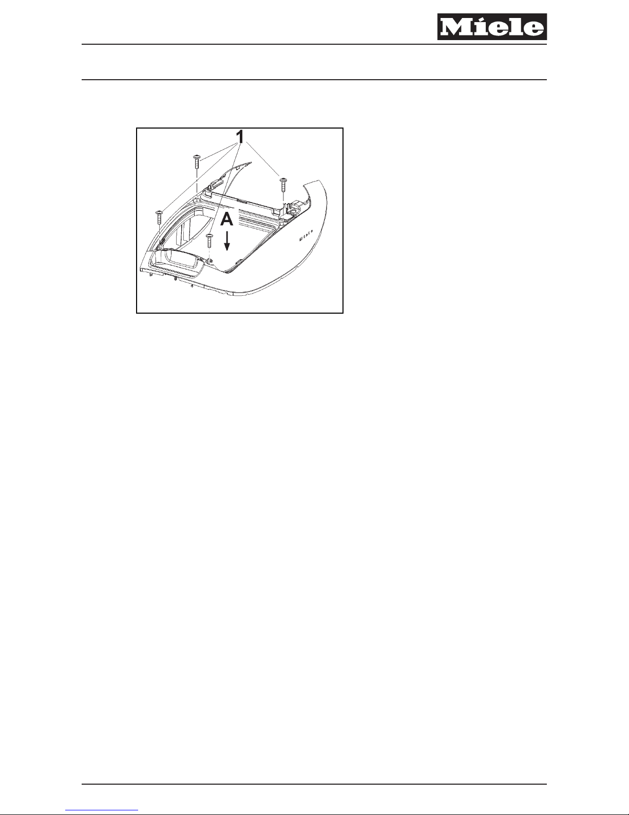
4.2 Cover Frame Removal
Fig. 2: Cover Frame
A Dust Compartment Lid Removal, 030 4.2.
A Remove the bag holder (Bag Holder Replacement, 020 4.1).
A Take off the seal surrounding the dust compartment.
A Take out the exhaust (HEPA or AirClean) filter and filter frame.
A Remove the four T20 screws securing the cover frame (020 Fig. 2, Pos. 1).
A Remove the right foot switch (cord rewind) (040 Fig. 8).
A Remove the retaining screw (T20) underneath.
A Push down inside the base and pull up on the cover frame to remove (020
Fig. 2, Pos. A). The bumper strip will also come off.
Descriptive Technical Documentation
DTD no. 41-8000 020-3
07.06.2013, US_am This information should not be duplicated or passed on without Miele approval. All rights reserved.
Page 15
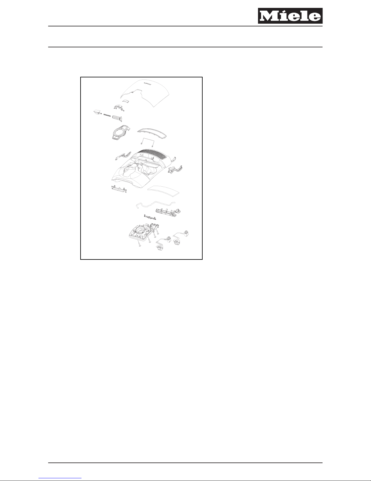
030 Dust Compartment Lid
x
Descriptive Technical Documentation
DTD no. 41-8000 030-1
07.06.2013, US_am This information should not be duplicated or passed on without Miele approval. All rights reserved.
Page 16
4 Service
4.1 Accessory Compartment Lid Removal
x
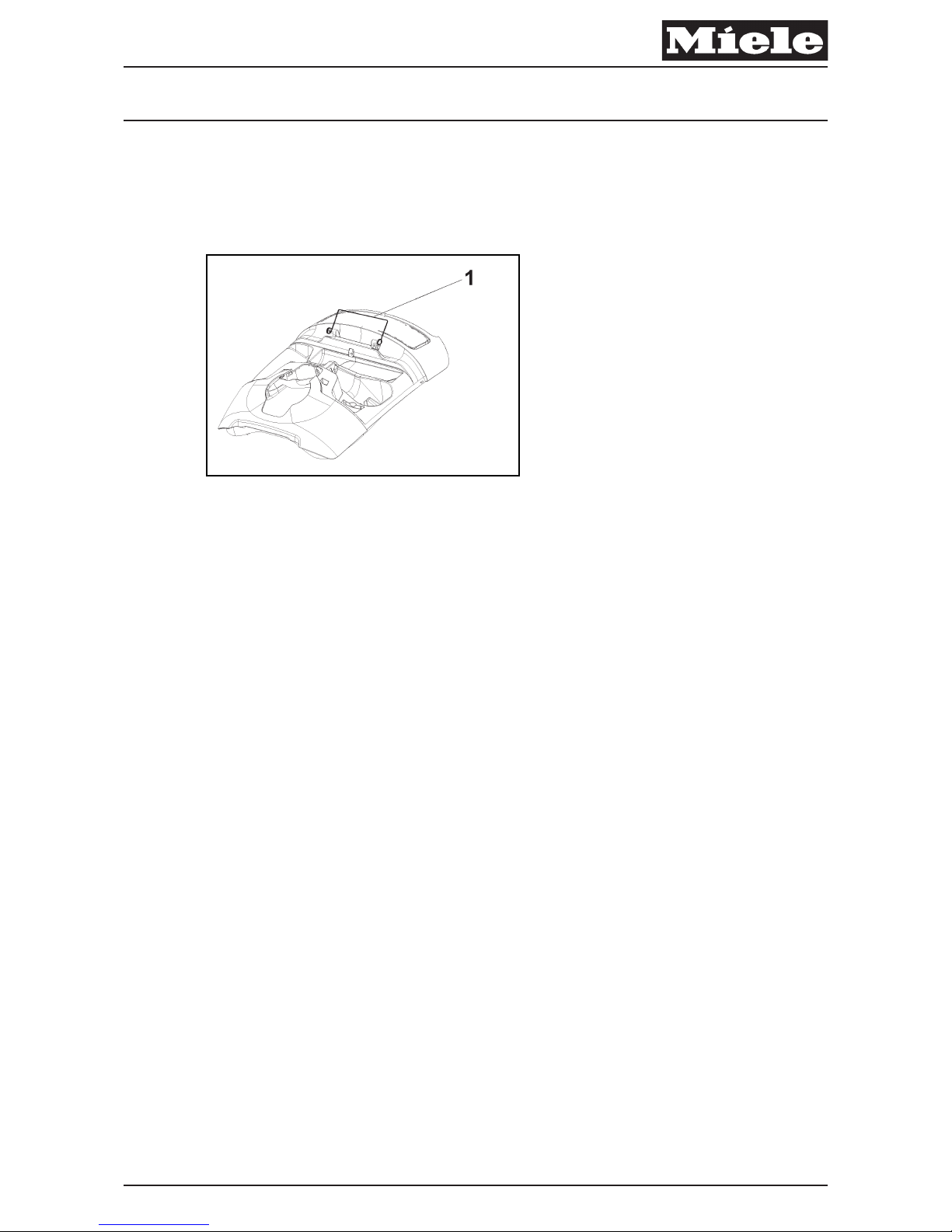
Fig. 1: Torsion Spring
A Open the lid approximately 2 inches.
A Hold the vacuum cleaner with one hand; with the other hand, lift the lid up and
disengage it from the pins.
A When reinstalling the lid, push it slowly onto the torsion spring (030 Fig. 1,
Pos. 1) and then onto the pins.
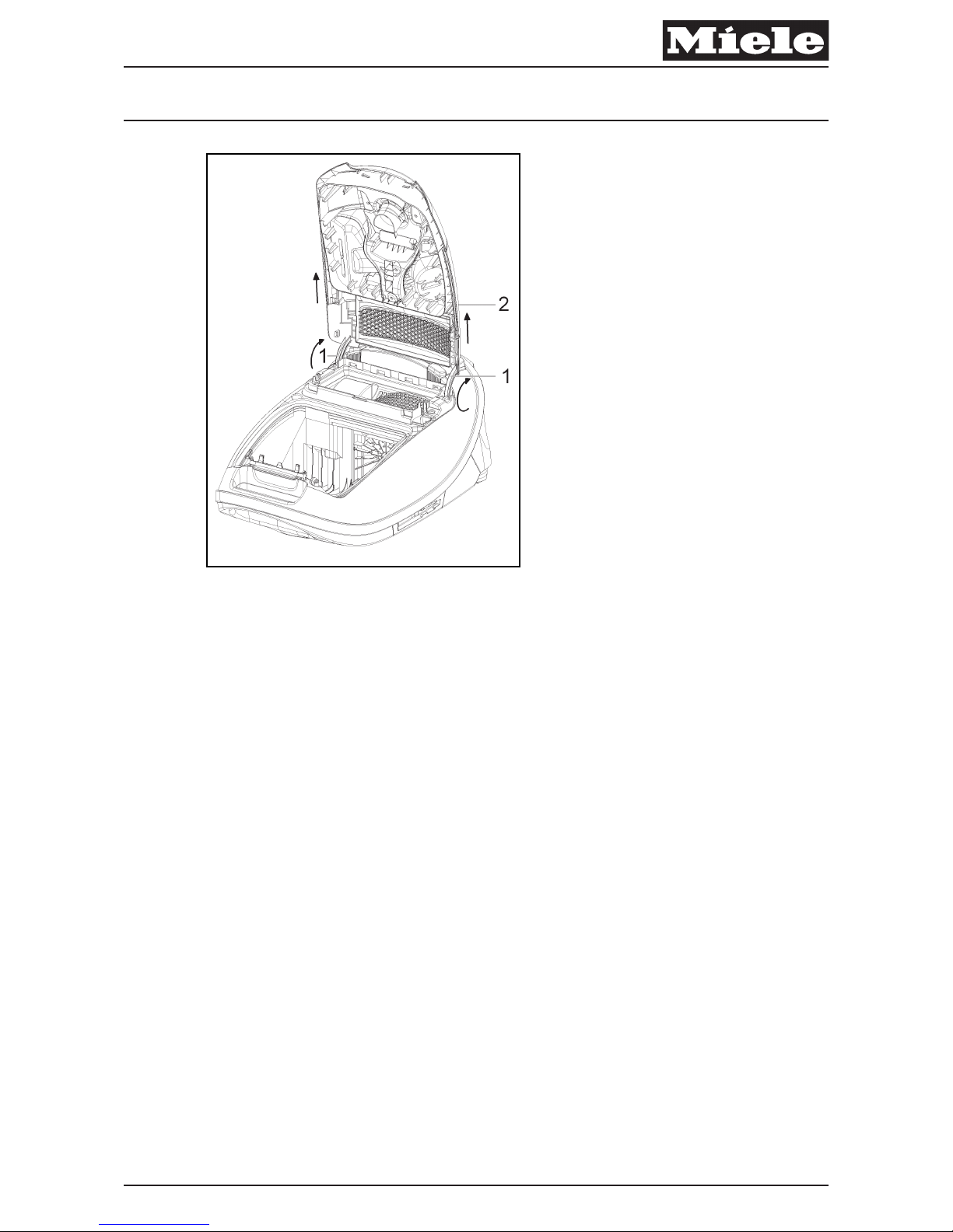
4.2 Dust Compartment Lid Removal
A Open the dust compartment lid to its stop.
A Bend the dust compartment lid backwards slightly to release it (030 Fig. 2,
Pos. 2).
A When reinstalling the lid, place the two hinges in their openings (030 Fig. 2,
Pos. 1), then slowly close the lid.
Descriptive Technical Documentation
030-2 DTD no. 41-8000
This information should not be duplicated or passed on without Miele approval. All rights reserved. 07.06.2013, US_am
Page 17
x
Fig. 2: Dust Compartment Lid
4.3 Dust Channel Assembly Removal
A Dust Compartment Lid Removal, 030 4.2.
A Remove the four T20 screws securing the dust channel assembly to the
underside of the dust compartment lid.
A Release the hinge socket from its retainers on the inside of the dust
compartment lid.
A On the outside of the dust compartment lid, press down forcefully on the
silver dust channel ring to release the dust channel assembly from the dust
compartment lid.
Descriptive Technical Documentation
DTD no. 41-8000 030-3
07.06.2013, US_am This information should not be duplicated or passed on without Miele approval. All rights reserved.
Page 18

4.4 Bag Change Indicator Removal
A Dust Channel Assembly Removal, 030 4.3.
A Pull up on the silver dust channel ring to separate it from the dust channel
(the locking latch for the accessory compartment lid may also come off).
A Release the “hose” end of the indicator (without the orange tab) from its
retainer on the dust channel; pull up to remove the indicator assembly, taking
care not to lose the spring that is inside the hose.
4.5 Hinge Socket Wiring Harness Removal
A Dust Channel Assembly Removal, 030 4.3.
A Pull up on the silver dust channel ring to separate it from the dust channel
(the locking latch for the accessory compartment lid may also come off).
A Release the wiring harness plug closest to the dust channel opening.
A Push the orange tab on the bag change indicator to the right to release the
wires underneath.
A Release the rest of the hinge socket wiring from the dust channel, pulling up
on retaining tabs as necessary.
A Release the other plug from its housing at the other end of the dust channel
assembly.
Descriptive Technical Documentation
030-4 DTD no. 41-8000
This information should not be duplicated or passed on without Miele approval. All rights reserved. 07.06.2013, US_am
Page 19
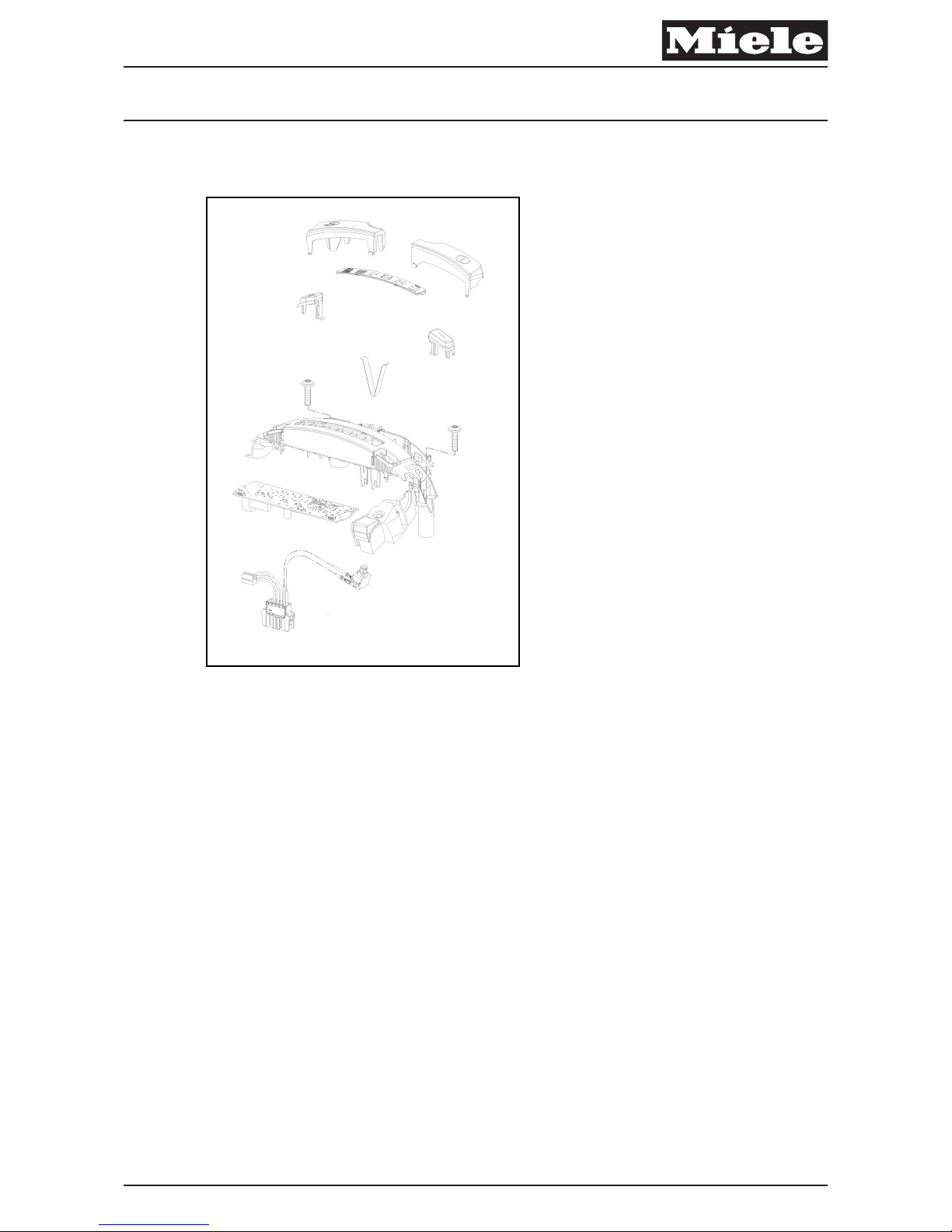
040 Operating Unit
x
Descriptive Technical Documentation
DTD no. 41-8000 040-1
07.06.2013, US_am This information should not be duplicated or passed on without Miele approval. All rights reserved.
Page 20
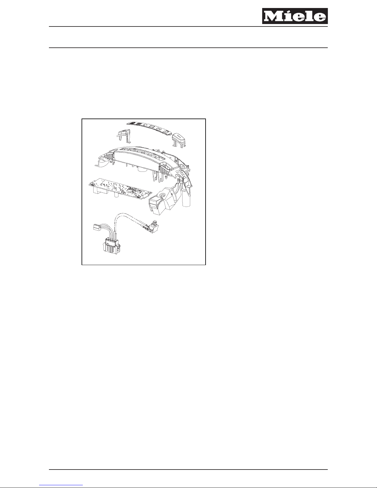
2 Function
2.1 Operating Units: S 83xx to S 89xx
2.1.1 S 83xx Series
x
Fig. 1: Operating Unit Overview for S 83xx
S 83xx models with +/- foot switch and thermal protection function of the motor
without indicator light.
Descriptive Technical Documentation
040-2 DTD no. 41-8000
This information should not be duplicated or passed on without Miele approval. All rights reserved. 07.06.2013, US_am
Page 21
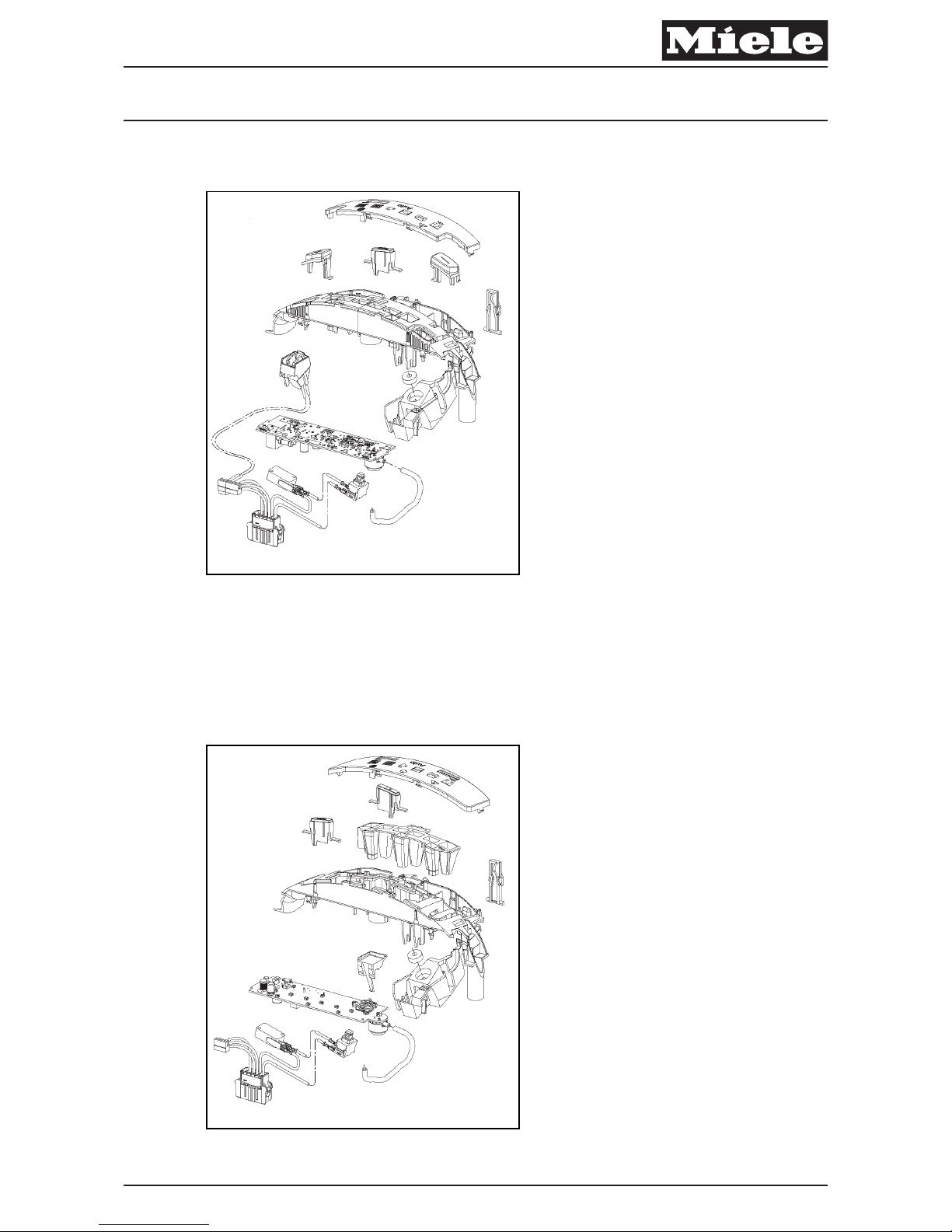
2.1.2 S 85xx Series
x
Fig. 2: Operating Unit Overview for S 85xx
S 85xx models with +/- foot switch, automatic suction power control and side
lighting (UniQ only). Thermal protection function of the motor with indicator light.
Park switch and reset button for the dust compartment filter change indicator.
2.1.3 S 87xx Series
x
Fig. 3: Operating Unit Overview for S 87xx
Descriptive Technical Documentation
DTD no. 41-8000 040-3
07.06.2013, US_am This information should not be duplicated or passed on without Miele approval. All rights reserved.
Page 22
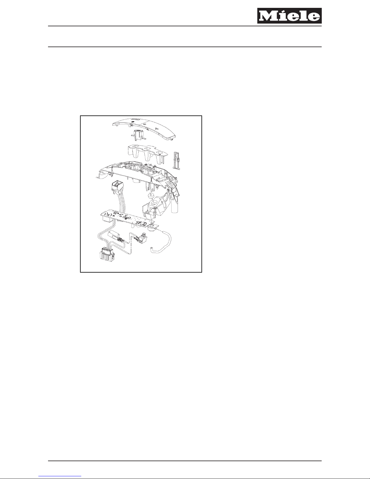
S 87xx series with automatic suction power control but without +/- foot switch.
Thermal protection function of the motor with indicator light. Park switch and reset
button for the dust compartment-change filter indicator. Handle with radio controls
as well as manual "on" button, in case the battery for the radio control dies.
2.1.4 S 89xx Series
x
Fig. 4: Operating Unit Overview for S 89xx
S 89xx series with automatic suction power control but without +/- foot switch.
Controls (on/off, power level, etc.) via cable in handle. Thermal protection function
of the motors with indicator light. Park switch and reset button for the dust
compartment-change filter indicator.
Descriptive Technical Documentation
040-4 DTD no. 41-8000
This information should not be duplicated or passed on without Miele approval. All rights reserved. 07.06.2013, US_am
Page 23
2.2 Automatic Suction Power Control
x
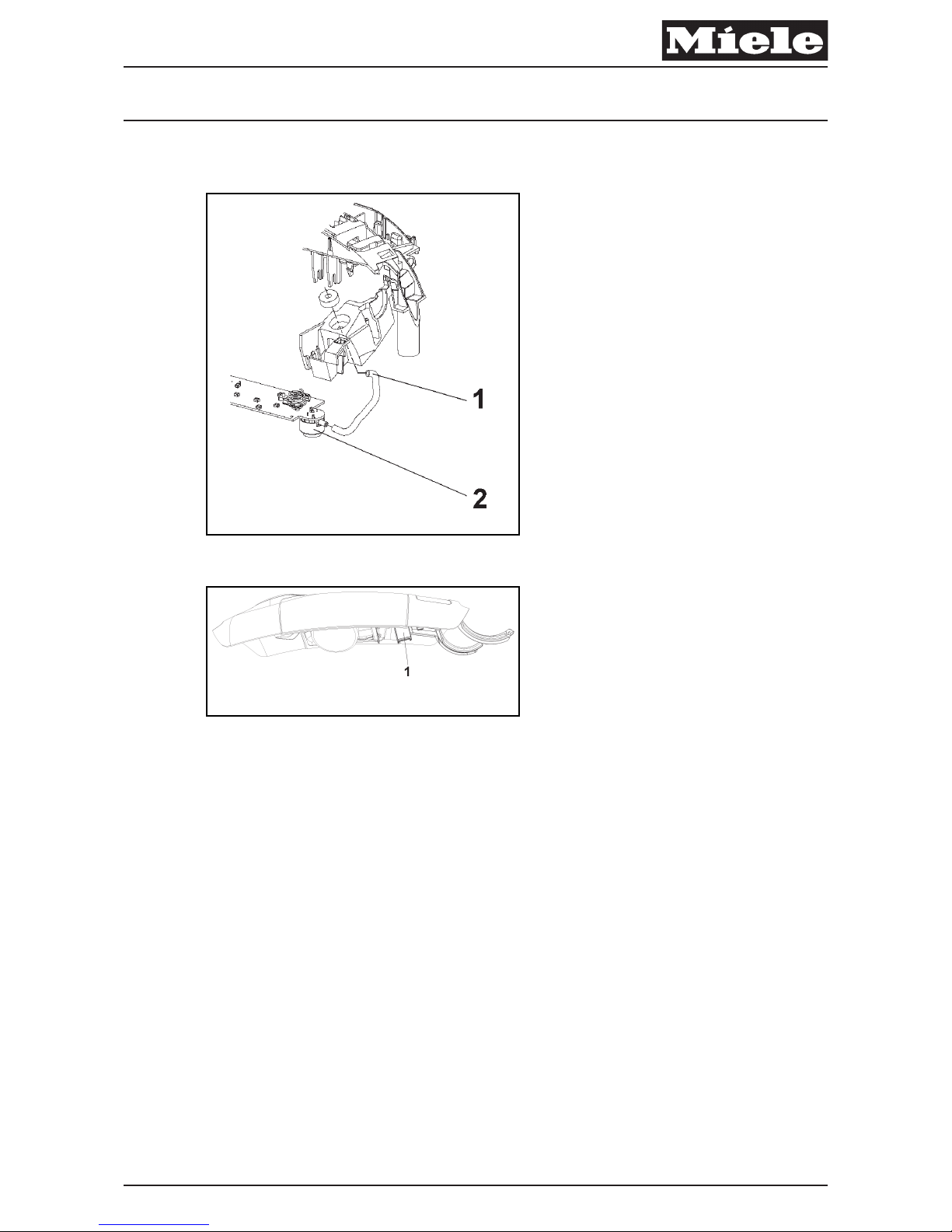
Fig. 5: Suction Power Control Components
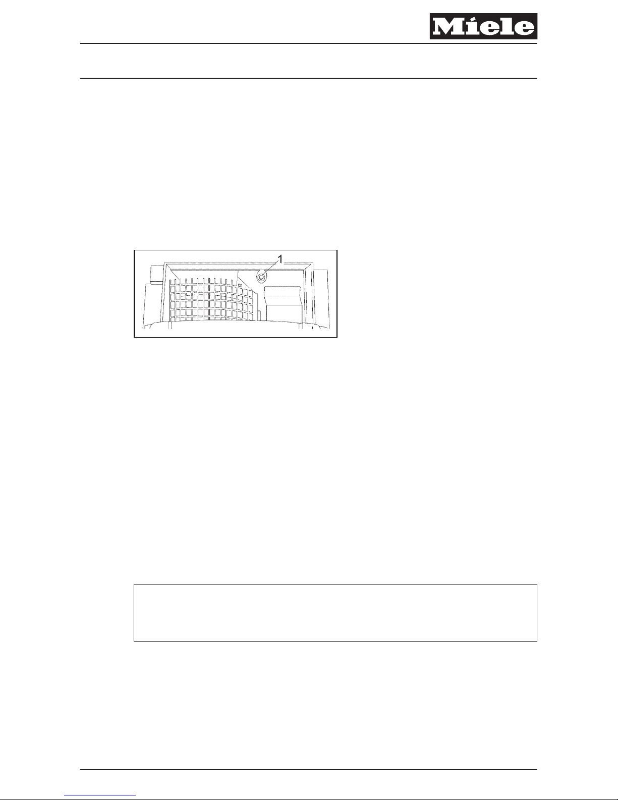
Fig. 6: Low-Pressure Channel Connection (1) in Casing Top
The built-in suction power control consists of a pressure sensor on the electronic
(040 Fig. 5, Pos. 2) that detects low pressure in the bag compartment via a hose
(040 Fig. 5, Pos. 1). The low pressure is measured and compared to a fixed value
programmed into the electronic. If these values do not match, the motor speed
will be automatically corrected.
– When the vacuum cleaner is switched on for the first time, it will switch on at
the "Auto" power setting.
– With subsequent uses, the vacuum cleaner will switch on at the last-used
power setting.
Descriptive Technical Documentation
DTD no. 41-8000 040-5
07.06.2013, US_am This information should not be duplicated or passed on without Miele approval. All rights reserved.
Page 24
3 Fault Repair
3.1 Motor Does Not React in the "Automatic" Setting or Always Runs
at High Speed
Cause
Low-pressure channel to the bag compartment is clogged.
Remedy
x
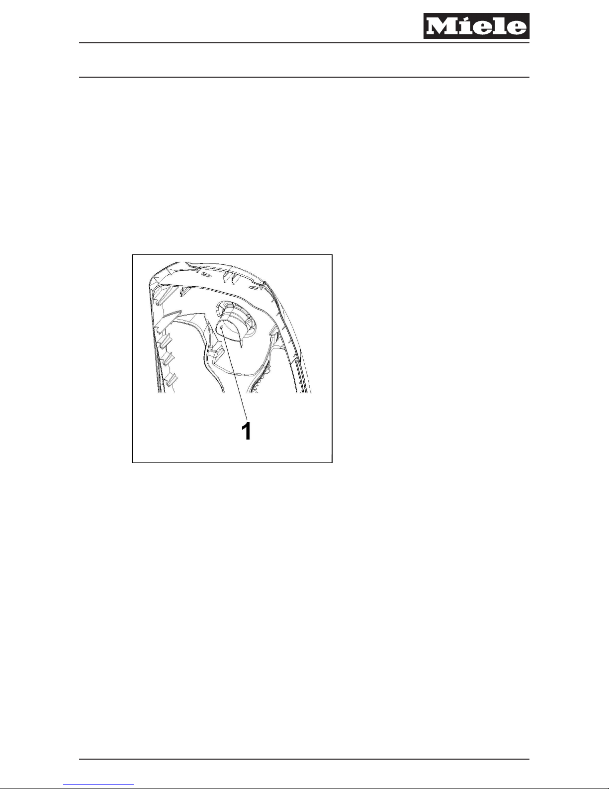
Fig. 7
A Check the low-pressure channel in the dust compartment lid (040 Fig. 7, Pos.
1) for clogs.
Cause
The hose between the pressure sensor and the dust compar tment is kinked or
damaged.
Remedy
A Cover Frame Removal, 020 4.2.
A Check the hose for damages, kinks or clogs; see 040 Fig. 5.
A If necessary, replace the hose.
Descriptive Technical Documentation
040-6 DTD no. 41-8000
This information should not be duplicated or passed on without Miele approval. All rights reserved. 07.06.2013, US_am
Page 25

x
Note
If the nozzle was run over smooth flooring (e.g., parquet or tile) while in the
“Automatic” setting, the motor will run at its highest speed due to the air coming
in at the sides of the nozzle.
Cause
Pressure sensor on the electronic board is defective.
Remedy
A Pull off the hose between the control panel and the dust compartment lid (040
Fig. 5, Pos. B).
A Switch the motor on in the "Automatic" setting.
A Generate a low-pressure condition at the disconnected end of the hose (e.g.,
quickly suck an object in).
A If the motor speed does not drop, then the pressure sensor is defective.
A Replace the electronic.
Descriptive Technical Documentation
DTD no. 41-8000 040-7
07.06.2013, US_am This information should not be duplicated or passed on without Miele approval. All rights reserved.
Page 26
4 Service
4.1 Operating Unit Removal
A Dust Channel Assembly Removal, 030 4.3.
A Take out the exhaust filter frame (and filter).
A Cover Frame Removal, 020 4.2.
x
Warning!
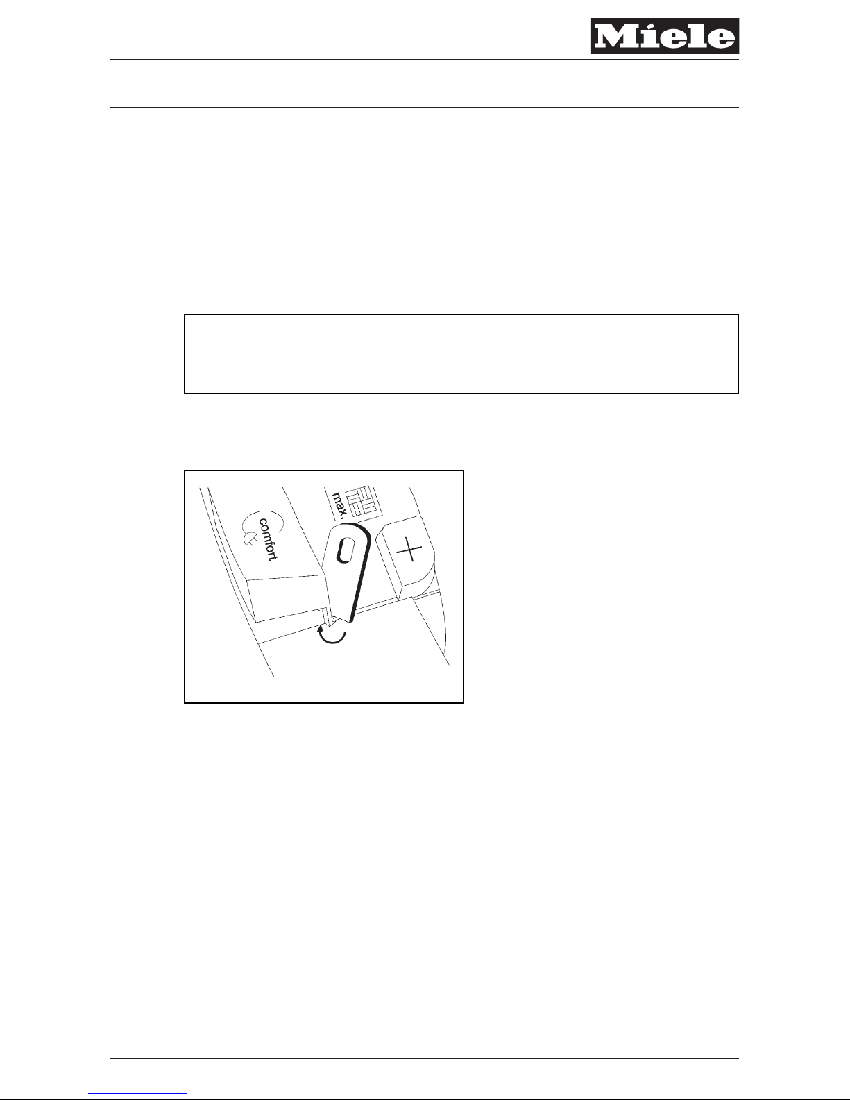
To avoid damaging the lacquered surface, do not lever out the foot switch with
sharp tools (screwdriver, etc.).
A Carefully lever out the two foot switches with a lid opener (mat. no. 05012752)
(040 Fig. 8).
x
Fig. 8: Foot Switch Removal
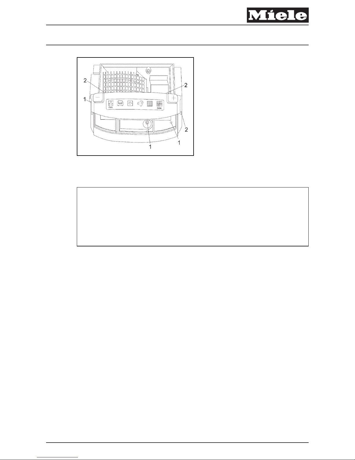
A Remove the three T20 screws (040 Fig. 9, Pos. 1).
A Take out the parking slot trim (it will come out on its own).
A Release the two front clips and one side clip with a small flathead screwdriver
(040 Fig. 9, Pos. 2), and remove the operating unit.
Descriptive Technical Documentation
040-8 DTD no. 41-8000
This information should not be duplicated or passed on without Miele approval. All rights reserved. 07.06.2013, US_am
Page 27
x
Fig. 9: Operating Unit Removal
A Reinstall by following these instructions in reverse order.
x
Note
If the operating unit cannot be easily reinstalled, check that the motor and the
cord reel are correctly seated in the base.
When removing the operating unit, the plugs between the operating unit and the
motor will also be disconnected. These plugs must be lined up exactly when reinserting the operating unit so that they can be snapped into place.
4.2 Electronic Board Removal
A Operating Unit Removal, 040 4.1.
A Turn the operating unit over; release the electronic board from its locking tabs
on the operating-unit casing.
A Disconnect the two Molex plugs from the electronic board.
Descriptive Technical Documentation
DTD no. 41-8000 040-9
07.06.2013, US_am This information should not be duplicated or passed on without Miele approval. All rights reserved.
Page 28
4.3 On/Off Switch Removal
A Operating Unit Removal, 040 4.1.
A Turn the operating unit over; release the on/off switch from its retainers on the
operating-unit casing.
A Disconnect the two wires from the on/off switch.
4.4 Powerbrush Outlet Wiring Harness Removal
A Operating Unit Removal, 040 4.1.
A Turn the operating unit over; disconnect the Molex end of the wiring harness
from the electronic.
A Release the wiring harness from its retainers on the operating-unit casing.
A Release the socket end of the wiring harness from its housing on the
operating-unit casing.
4.5 Park Switch Replacement (Model-Dependent)
x
Fig. 10: Park Switch
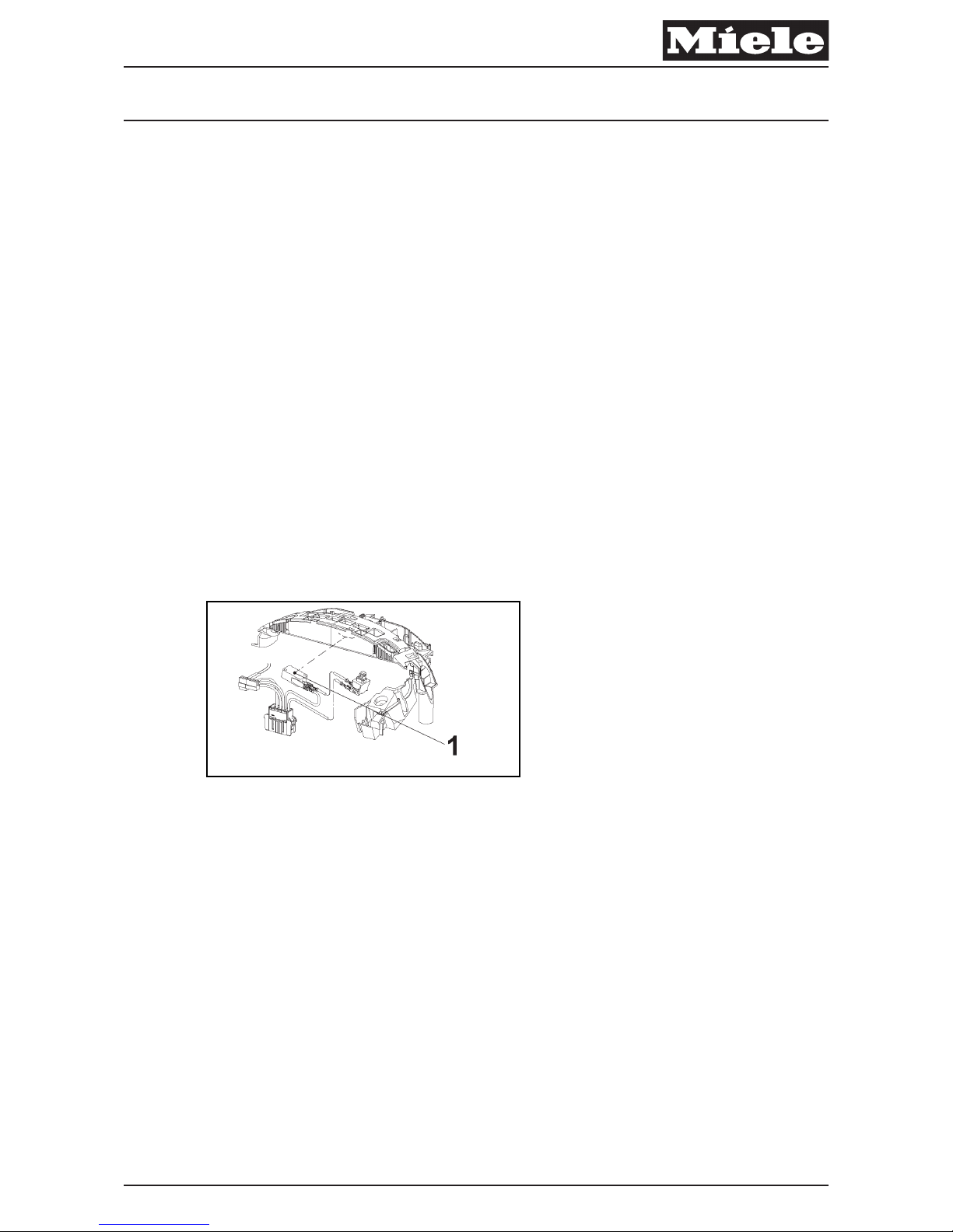
A Operating Unit Removal, 040 4.1.
A Disconnect and remove the Park switch (040 Fig. 10, Pos. 1).
Descriptive Technical Documentation
040-10 DTD no. 41-8000
This information should not be duplicated or passed on without Miele approval. All rights reserved. 07.06.2013, US_am
Page 29
050 Motor, Cord Reel
x
Descriptive Technical Documentation
DTD no. 41-8000 050-1
07.06.2013, US_am This information should not be duplicated or passed on without Miele approval. All rights reserved.
Page 30
2 Function
2.1 Thermal Protection Function
x
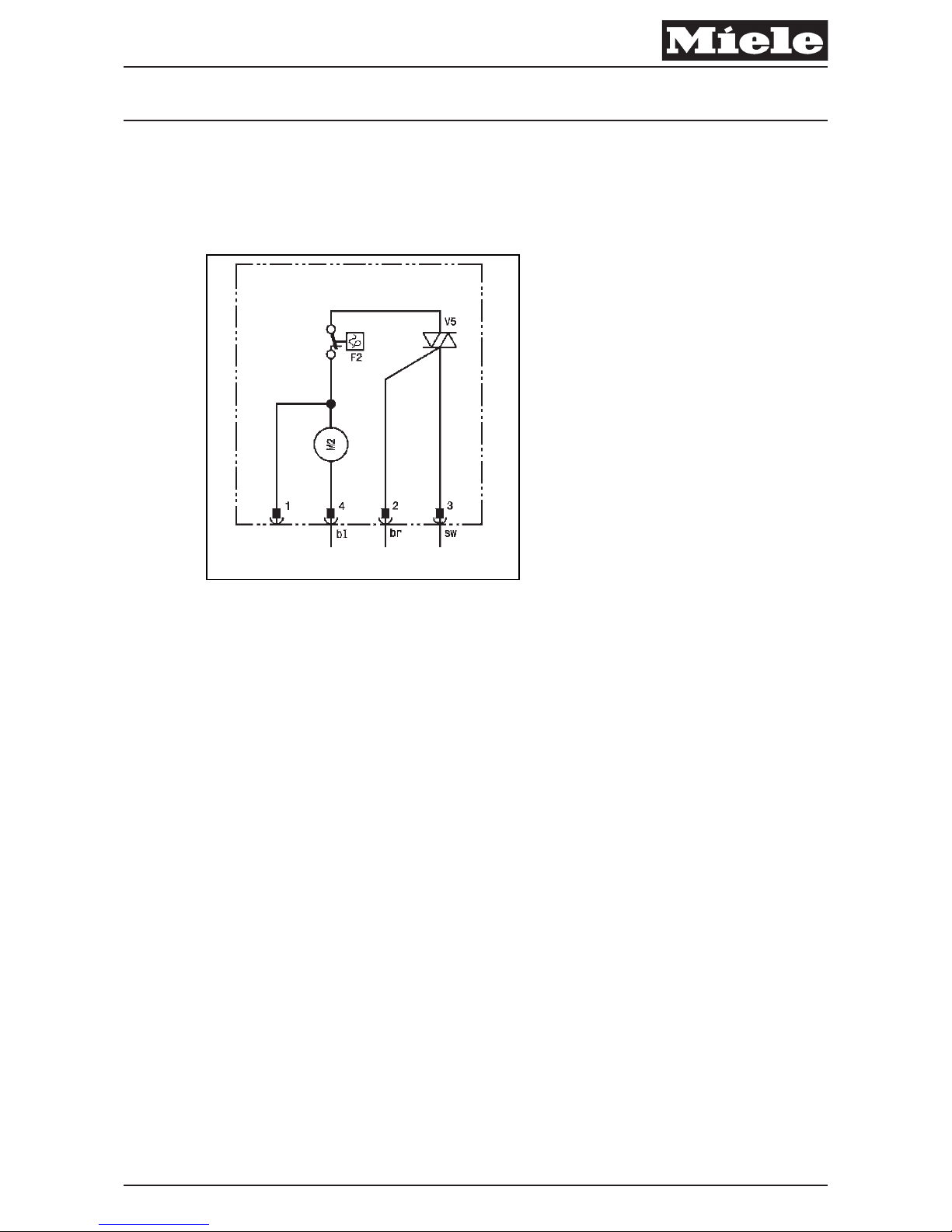
Fig. 1: Thermal Limiter F2 (Taken from Wiring Diagram)
Temperature limiter F2 (050 Fig. 1) is integrated into the motor winding and will
interrupt power if the motor should overheat. For some models this will also be
indicated via an indicator light on the operating unit. The temperature limiter will
reset itself after the motor cools down (approx. 30 minutes). This component is
part of the motor assembly and cannot be replaced individually.
Descriptive Technical Documentation
050-2 DTD no. 41-8000
This information should not be duplicated or passed on without Miele approval. All rights reserved. 07.06.2013, US_am
Page 31
3 Fault Repair
3.1 Suction Power Too Low
Cause
Floor nozzle or suction hose is clogged.
Remedy
A Clean the floor nozzle and/or suction hose.
Cause
Dustbag is full.
Remedy
A Change the dustbag.
x
Note
The dustbag must be changed when the window in the bag change indicator is
completely red or the corresponding LED (model-dependent) lights up.
Cause
Pre-motor filter clogged.
Remedy
A Pre-motor filter exchange.
x
Note
The pre-motor filter must always be changed when a new packet of Miele
dustbags is opened. Each package of Miele dustbags contains a pre-motor filter.
Cause
Exhaust filter clogged.
Remedy
A Change the exhaust filter.
Descriptive Technical Documentation
DTD no. 41-8000 050-3
07.06.2013, US_am This information should not be duplicated or passed on without Miele approval. All rights reserved.
Page 32
x
Note
1. Super AirClean
This exhaust filter must always be changed when a new packet of Miele
dustbags is opened. Each package of Miele dustbags includes a Super Air
Clean exhaust filter.
2. Active AirClean – Active HEPA
This exhaust filter must be changed once a year. The date of replacement
can be written directly on the filter.
3.2 Motor Does Not Run
Cause
Park switch jams after pulling out the suction hose.
Remedy
A Check the Park switch function.
A If necessary, replace the Park switch; see Park Switch Replacement (Model-
Dependent), 040 4.5.
Cause
Motor winding defective.
Remedy
A Operating Unit Removal, 040 4.1.
A Check motor winding continuity.
A If no continuity, see Motor Replacement, 050 4.2.
x
Note
When removing the operating unit, the plugs between the operating unit and the
motor will also be disconnected. These plugs must be lined up exactly when reinserting the operating unit so that they can be snapped into place.
Cause
The motor winding is too hot and the thermal protection function has tripped.
Descriptive Technical Documentation
050-4 DTD no. 41-8000
This information should not be duplicated or passed on without Miele approval. All rights reserved. 07.06.2013, US_am
Page 33
Remedy
A Disconnect power to the vacuum cleaner (pull the plug) and let the motor cool
off for approximately 20 to 30 minutes.
A To speed up the cooldown process, open the lid to the dust compartment and
take out the dust compartment filter.
A Check the suction hose for clogs.
A Check that the motor turns freely when rotated by hand.
A Replace any extremely dirty dustbags or exhaust and pre-motor filters.
A Check the function of the vent; the spring must be able to move freely.
A Do not switch the motor on again; see Motor Replacement, 050 4.2.
Cause
Carbon brushes are used up.
Remedy
A Replace the motor; see Motor Replacement, 050 4.2.
x
Note
The motor's built-in thermal limiter (F2) and carbon brushes are part of the motor
assembly and can not be exchanged separately.
Descriptive Technical Documentation
DTD no. 41-8000 050-5
07.06.2013, US_am This information should not be duplicated or passed on without Miele approval. All rights reserved.
Page 34
4 Service
4.1 Motor/Cord Reel Cover Removal
A Cover Frame Removal, 020 4.2.
A Operating Unit Removal, 040 4.1.
A Remove the T20 screw at the front of the motor cover (050 Fig. 2, Pos. 1).
A Remove the motor cover as one piece.
x
Fig. 2
4.2 Motor Replacement
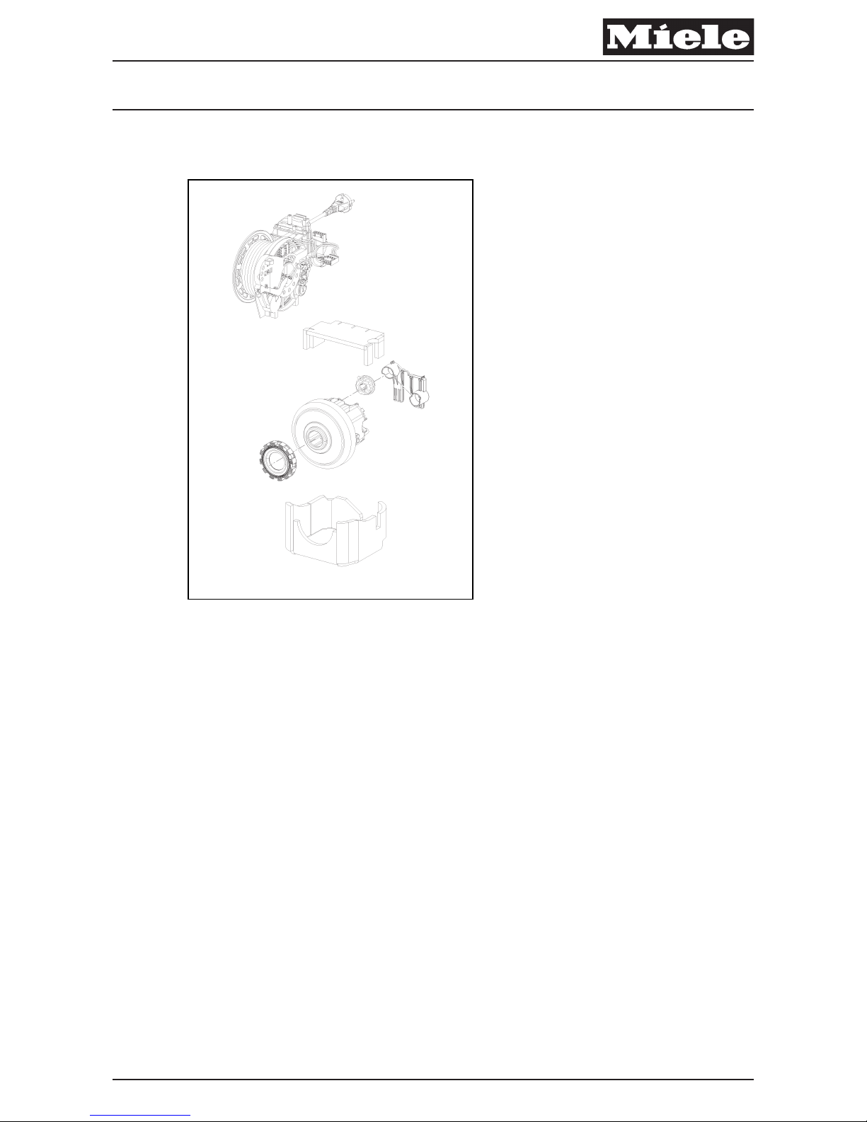
A Motor/Cord Reel Cover Removal, 050 4.1
A Disconnect the Molex plug from the motor.
A Lift the motor straight out of the base.
A Remove the white plastic motor bracket from the motor casing, along with the
two rubber cushions.
A Use a flathead screwdriver to release the three clips holding the two casing
halves together.
A Separate the casing halves and take out the motor.
A Reinstall by following these instructions in reverse order.
x
Note
When reassembling, make sure that the motor wiring and the plug connection to
the operating unit are correctly installed in their guides.
Descriptive Technical Documentation
050-6 DTD no. 41-8000
This information should not be duplicated or passed on without Miele approval. All rights reserved. 07.06.2013, US_am
Page 35
4.3 Cord Reel Replacement
Note
The cord reel and cord form one assembly and can only be replaced together.
A Cover Frame Removal, 020 4.2.
A Operating Unit Removal, 040 4.1.
A Release the right and left sides of the cord reel and lever the cord reel out,
using a flathead screwdriver as necessary.
A Reinstall by following these instructions in reverse order.
x
Note
When re-installing the cord reel, make sure that the seal on the motor/cord reel
wiring harness is installed correctly in its groove on the motor seal before
pressing the cord reel assembly into place.
4.4 Pre-Motor Filter Frame Removal
A Take out the cord reel, referring to Cord Reel Replacement, 050 4.3 as
necessary.
A Remove the parking slot screw (T20) on the motor side and take out the
parking slot.
A Open the pre-motor filter frame.
A Press in on the blue pins (one was obscured by the cord reel and the other by
the parking slot) using a suitable tool.
Descriptive Technical Documentation
DTD no. 41-8000 050-7
07.06.2013, US_am This information should not be duplicated or passed on without Miele approval. All rights reserved.
Page 36
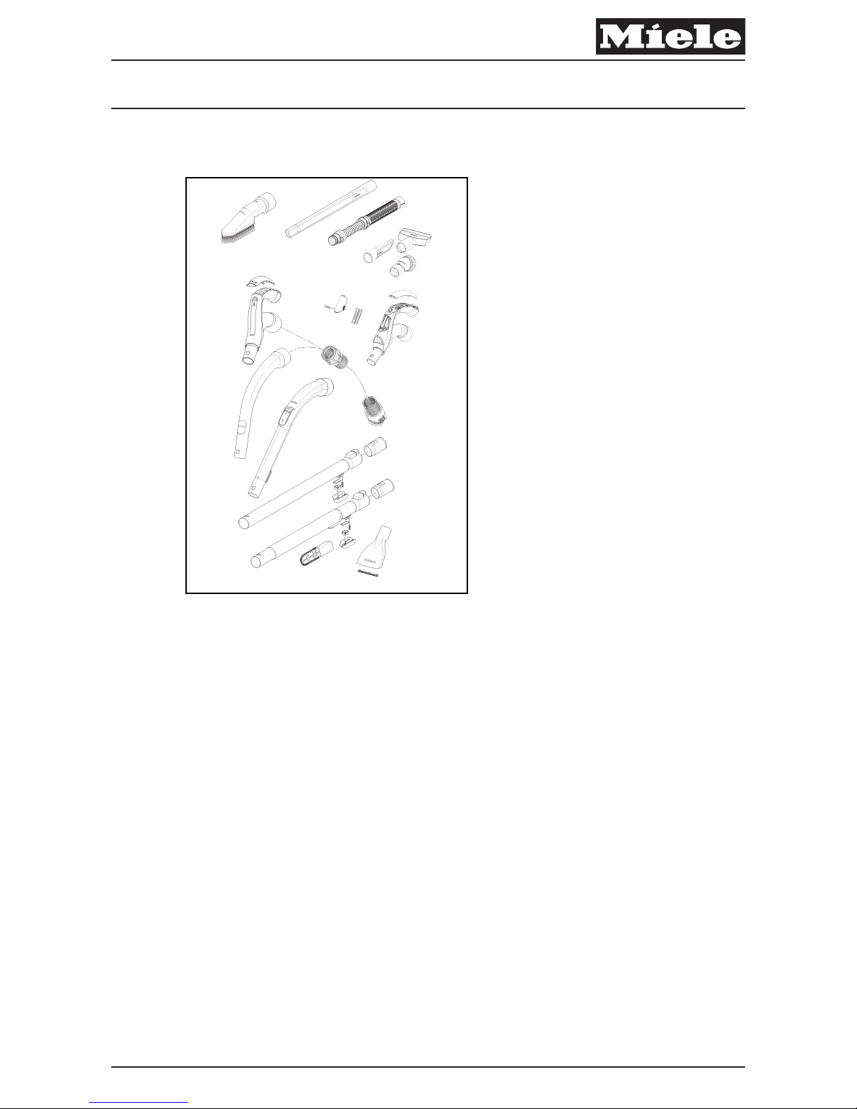
060 Suction Hose, Handle (S 83xx)
x
Descriptive Technical Documentation
DTD no. 41-8000 060-1
07.06.2013, US_am This information should not be duplicated or passed on without Miele approval. All rights reserved.
Page 37

3 Fault Repair
3.1 LEDs in LED Handle Do Not Light
Cause
The 3 batteries in the handle are dead.
Remedy
A Replace the batteries; see LED Handle Battery Replacement (Model-
Dependent), 060 4.3.
Descriptive Technical Documentation
060-2 DTD no. 41-8000
This information should not be duplicated or passed on without Miele approval. All rights reserved. 07.06.2013, US_am
Page 38
4 Service
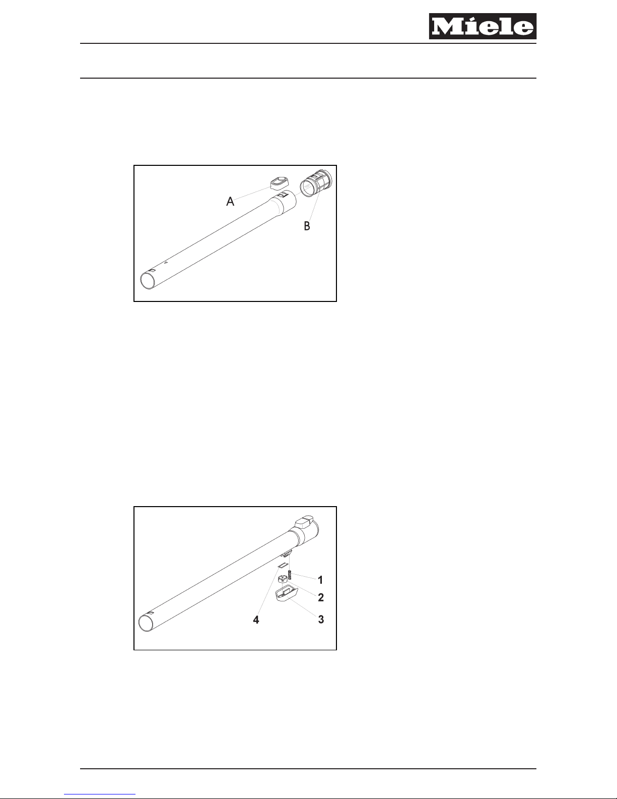
4.1 Telescopic Suction Hose Locking Piece Replacement
x
Fig. 1: Telescopic Hose Locking Piece
A Release the old locking piece with a small flathead screwdriver.
A Remove the cap (060 Fig. 1, Pos. A). The pushbutton and spring underneath
will be released as well.
A The insert (060 Fig. 1, Pos. B) will also come out when the locking piece is
removed.
A When installing, first insert the pushbutton.
A Press and hold the pushbutton while sliding the insert into the suction hose.
4.2 Pushbutton Replacement
x
Fig. 2: Pushbutton
A Pry off the old pushbutton with a small flathead screwdriver.
A Place the bar (060 Fig. 2, Pos. 4) in its holder.
A Place the spring (060 Fig. 2, Pos. 1) in its holder.
A Place the pushbutton (060 Fig. 2, Pos. 2) on the bar.
Descriptive Technical Documentation
DTD no. 41-8000 060-3
07.06.2013, US_am This information should not be duplicated or passed on without Miele approval. All rights reserved.
Page 39
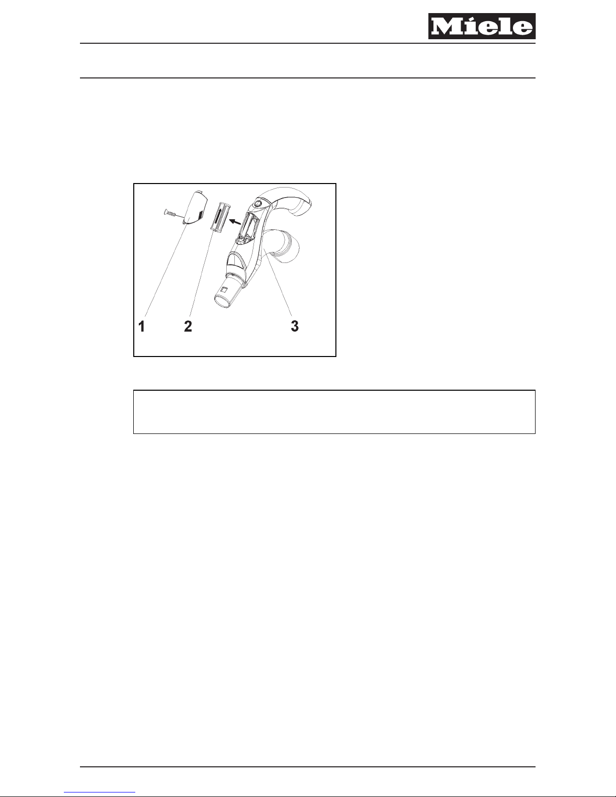
A Push the housing (060 Fig. 2, Pos. 3) into position.
A Check for correct function.
4.3 LED Handle Battery Replacement (Model-Dependent)
x
Fig. 3: Battery in LED Handle
Note
Three 1.5V AAA batteries required.
A Remove the retaining screw (060 Fig. 3, Pos. 1) from the handle (060 Fig. 3,
Pos. 3).
A Press the two locking tabs on the sides of the battery cover and remove the
cover (060 Fig. 3, Pos. 1).
A Remove the battery holder (060 Fig. 3, Pos. 2).
A Take the 3 old batteries out of the battery holder and insert the 3 new
batteries. Observe polarity.
A Re-install the battery holder. There is an arrow imprinted in the battery
compartment and on the battery holder that indicates which direction the
batteries must be facing.
A Screw the cover back in place.
Descriptive Technical Documentation
060-4 DTD no. 41-8000
This information should not be duplicated or passed on without Miele approval. All rights reserved. 07.06.2013, US_am
Page 40
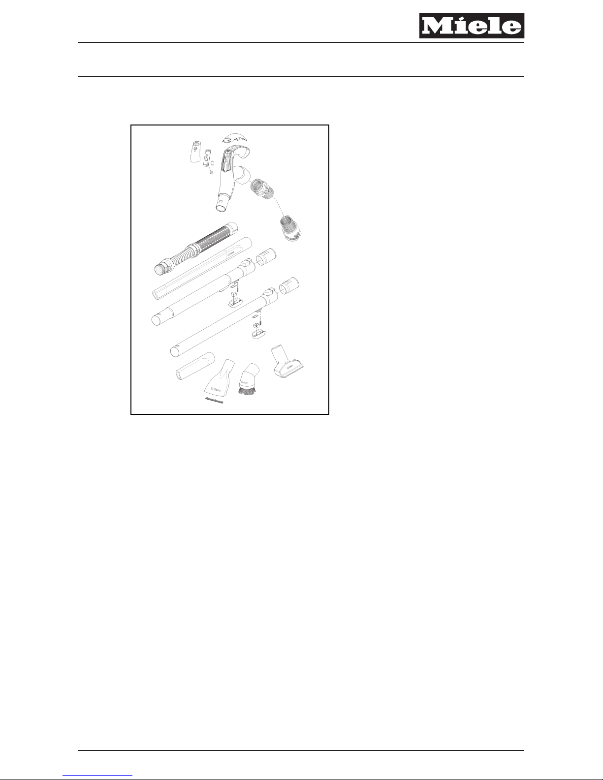
061 Radio-Controlled Suction Hose (S 87xx)
x
Descriptive Technical Documentation
DTD no. 41-8000 061-1
07.06.2013, US_am This information should not be duplicated or passed on without Miele approval. All rights reserved.
Page 41

3 Fault Repair
3.1 Radio-Controlled Handle Not Functioning
Cause
Battery is dead.
Remedy
A Replace the battery; see Battery in Radio-Controlled Handle Replacement
(Model-Dependent), 061 4.1.
Descriptive Technical Documentation
061-2 DTD no. 41-8000
This information should not be duplicated or passed on without Miele approval. All rights reserved. 07.06.2013, US_am
Page 42
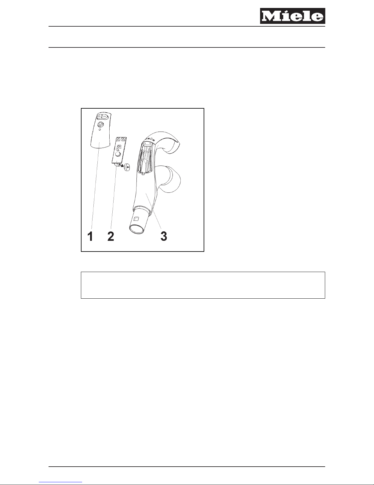
4 Service
4.1 Battery in Radio-Controlled Handle Replacement (ModelDependent)
x
Fig. 1: Battery in Radio-Controlled Handle
Note
The battery (3V button-cell CR 2032) should be replaced every 18 months.
A With a screwdriver, carefully release the cover of the battery compartment
(061 Fig. 1, Pos.1) on the handle (061 Fig. 1, Pos. 3).
A Press out the old battery (061 Fig. 1, Pos. 2) and install a new one. Observe
polarity.
Descriptive Technical Documentation
DTD no. 41-8000 061-3
07.06.2013, US_am This information should not be duplicated or passed on without Miele approval. All rights reserved.
 Loading...