

Page 1

TECHNICAL INFORMATION
S 500 and S 600 Canister Vacuums
© 2011 Miele USA
Page 2

S 500 & S 600 Canister Vacuums
Technical Information
Table of Contents
A Warning and Safety Instructions ........................................................................ 6
1 General Information .............................................................................................. 6
2 Cleaning and Care ................................................................................................ 6
2.1 Vacuums and Accessories ..................................................................................... 6
2.2 Dust Compartment ................................................................................................. 6
B Modification History ............................................................................................ 7
C Technical Data ..................................................................................................... 7
D Layout of Electrical Components ..................................................................... 11
1 S 51x Models ...................................................................................................... 11
2 S 52x and S 53x Models ..................................................................................... 12
3 S 54x and S 55x Models ..................................................................................... 13
4 S 62x Models ...................................................................................................... 14
5 S 65x Models ...................................................................................................... 15
6 Accessories ........................................................................................................ 15
6.1 Accessory Holder ................................................................................................. 16
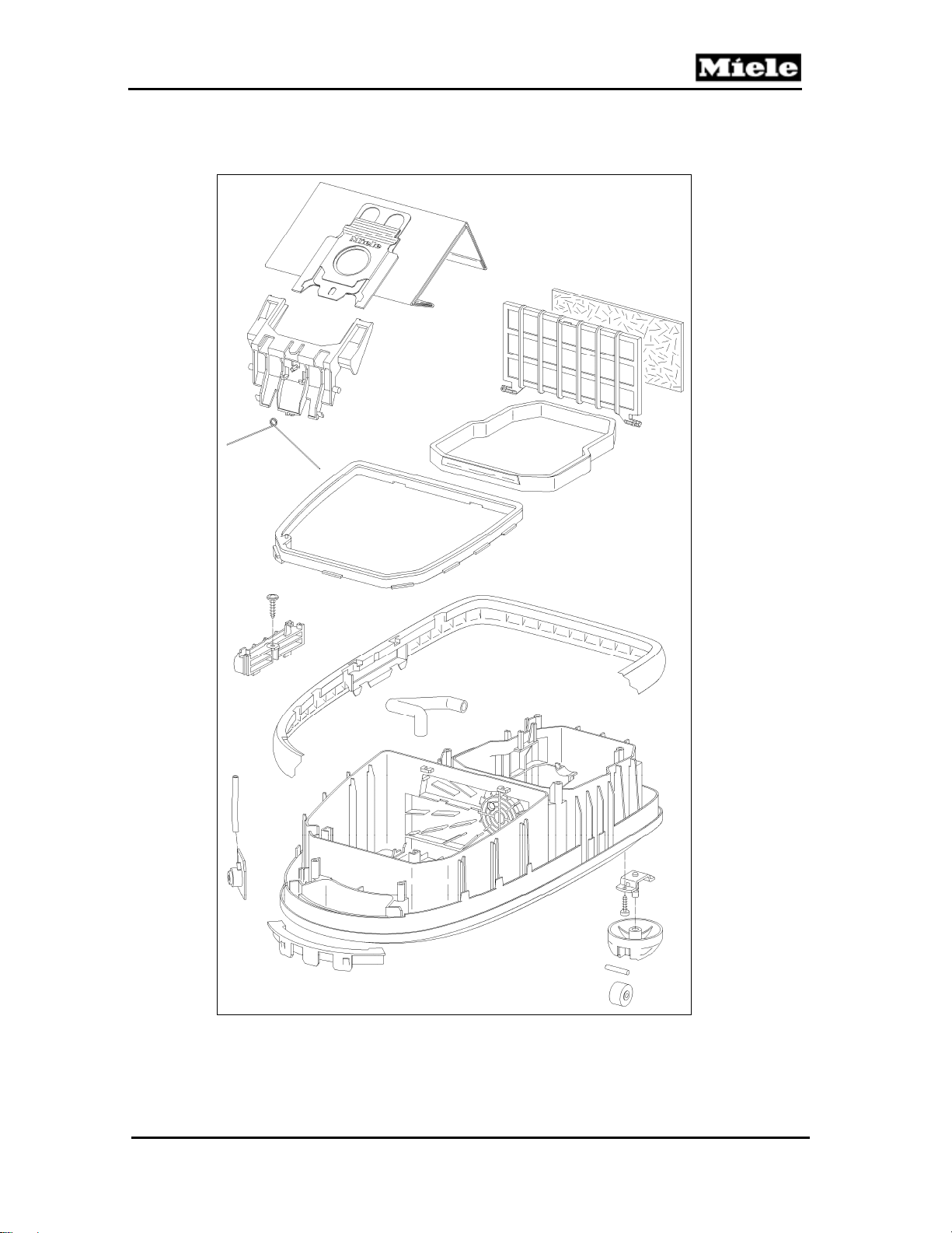
010 Casing Bottom ................................................................................................... 17
2 Function .............................................................................................................. 18
2.1 Dustbags .............................................................................................................. 18
2.2 Filters .................................................................................................................... 18
4 Service ................................................................................................................ 19
4.1 Storage Slot Removal .......................................................................................... 19
4.2 Bumper Strip Removal ......................................................................................... 19
4.3 Seal and Sealing Ring Removal .......................................................................... 19
4.4 Caster Removal ................................................................................................... 20
4.5 Bag Holder Removal ............................................................................................ 21
4.6 Changing the Bag ................................................................................................ 22
4.7 Replacing the Super Air Clean Filter .................................................................... 22
4.8 Replacing the Active Air Clean or Active HEPA Filter ......................................... 22
4.9 Replacing One Type of Filter with Another .......................................................... 23
4.10 Changing the Dust Compartment (Motor Protection) Filter ................................. 23
4.11 Vacuum Pressure Monitor Removal .................................................................... 24
020 Casing Top ......................................................................................................... 25
3 Fault Repair ........................................................................................................ 26
3.1 Bag Change Indicator Reacts Too Late ............................................................... 26
3.2 Bag Change Indicator Reacts Too Early .............................................................. 26
3.3 Accessory Compartment Lid Difficult to Close ..................................................... 27
3.4 Accessory Compartment Lid Difficult to Open ..................................................... 27
3.5 Accessory Compartment Lid Rocks Back and Forth ........................................... 28
4 Service ................................................................................................................ 28
4.1 Accessory Compartment Lid Removal ................................................................. 28
4.2 Casing Top Removal ............................................................................................ 29
4.3 Casing Top Installation ......................................................................................... 30
4.4 Casing Top Replacement ..................................................................................... 30
4.5 Cover Frame Removal ......................................................................................... 31
4.6 Bag Change Indicator Removal ........................................................................... 31
4.7 Slide Sleeve and Dust Channel Removal ............................................................ 32
4.8 Slide Sleeve and Dust Channel Installation ......................................................... 33
4.9 Slide Shutter Replacement .................................................................................. 35
4.10 Casing Top Catch Removal (S 500 Models) ........................................................ 35
2
Page 3

500 & S 600 Canister Vacuums
Technical Information
4.11
Casing Top Catch Removal (S 600 Models) ........................................................ 35
4.12 Casing Top Catch Installation (S 500 Models) ..................................................... 36
4.13 Casing Top Catch Installation (S 600 Models) ..................................................... 36
4.14 Built-In Socket Removal ....................................................................................... 37
4.15 Built-In Socket Installation .................................................................................... 40
030 Operating Unit .................................................................................................... 42
3 Fault Repair ........................................................................................................ 43
3.1 Vacuum Cleaner Cannot Be Switched On ........................................................... 43
3.2 Vacuum Cleaner Shuts Itself Off or Overheating Indicator LED Lights Up ......... 43
3.3 Fuse Trips ............................................................................................................ 44
3.4 Cord Is Not Fully Rewound .................................................................................. 44
3.5 Autoreverse Slide Blocked ................................................................................... 44
3.6 Electronics Troubleshooting ................................................................................. 45
4 Service ................................................................................................................ 49
4.1 Cap Removal ....................................................................................................... 49
4.2 Cap Installation .................................................................................................... 49
4.3 Cord Reel Removal .............................................................................................. 50
4.4 Cord Removal ...................................................................................................... 50
4.5 On/Off Switch Removal ........................................................................................ 52
4.6 Foot Switch Removal ........................................................................................... 52
4.7 Plug Housing Removal ......................................................................................... 53
4.8 Potentiometer (and Indicator Light) Removal (S 51x) .......................................... 54
4.9 Potentiometer and Indicator Light Removal (S 52x, S 62x) ................................. 55
4.10 Gear Rack Removal and Installation (S 52x, S 62x) ........................................... 56
4.11 Park System Switch Removal .............................................................................. 57
4.12 Cap Electronic Replacement ................................................................................ 57
040 Motor ................................................................................................................... 58
4 Service ................................................................................................................ 59
4.1 Motor Removal ..................................................................................................... 59
4.2 Damping Plate Removal ...................................................................................... 59
4.3 Carbon Brush Removal ........................................................................................ 59
4.4 Motor Electronic Replacement ............................................................................. 60
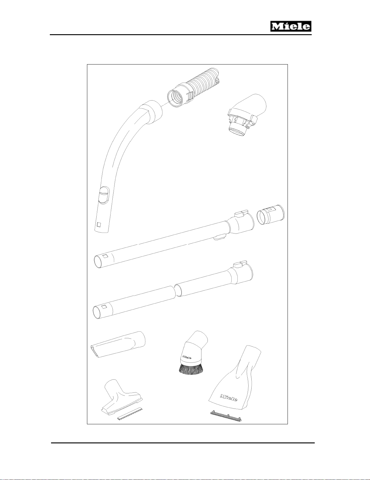
050 Suction Hose ...................................................................................................... 61
3 Fault Repair ........................................................................................................ 62
3.1 Suction Power Is Too Low ................................................................................... 62
3.2 Elbow Not Seated Correctly in the Suction Opening ........................................... 62
3.3 Elbow Blocked ...................................................................................................... 62
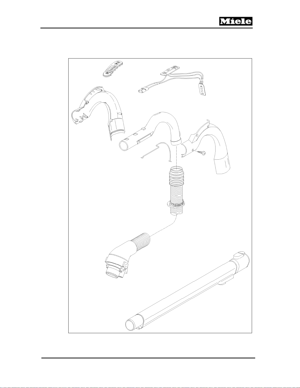
055 Electro Suction Hose ......................................................................................... 63
3 Fault Repair ........................................................................................................ 64
3.1 Suction Power Is Too Low ................................................................................... 64
3.2 Elbow Not Seated Correctly in the Suction Opening ........................................... 64
3.3 Elbow Blocked ...................................................................................................... 64
3.4 Appliance Always Operates at Full Power ........................................................... 64
3.5 Appliance Cannot Be Switched On ...................................................................... 65
3.6 Power Level Cannot Be Adjusted ........................................................................ 65
3.7 Electrobrush Cannot Be Selected ........................................................................ 65
4 Service ................................................................................................................ 65
4.1 Replacing the Suction Hose with Electronic ........................................................ 65
3
Page 4

S 500 & S 600 Canister Vacuums
Technical Information
List of Figures
Figure D-1: S 51x Component Layout .............................................................................. 11
Figure D-2: S 52x and S 53x Component Layout ............................................................. 12
Figure D-3: S 54x and S 55x Component Layout ............................................................. 13
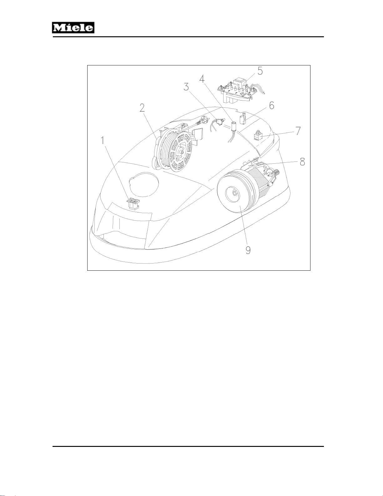
Figure D-4: S 62x Component Layout .............................................................................. 14
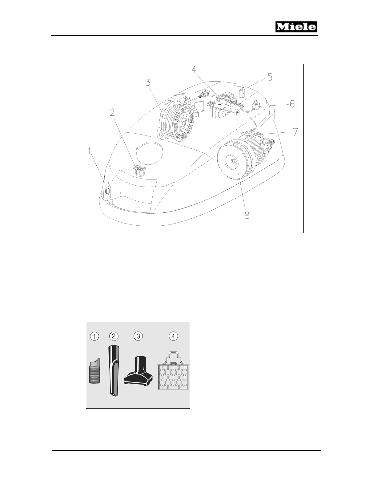
Figure D-5: S 65x Component Layout .............................................................................. 15
Figure D-6: Accessories ................................................................................................... 15
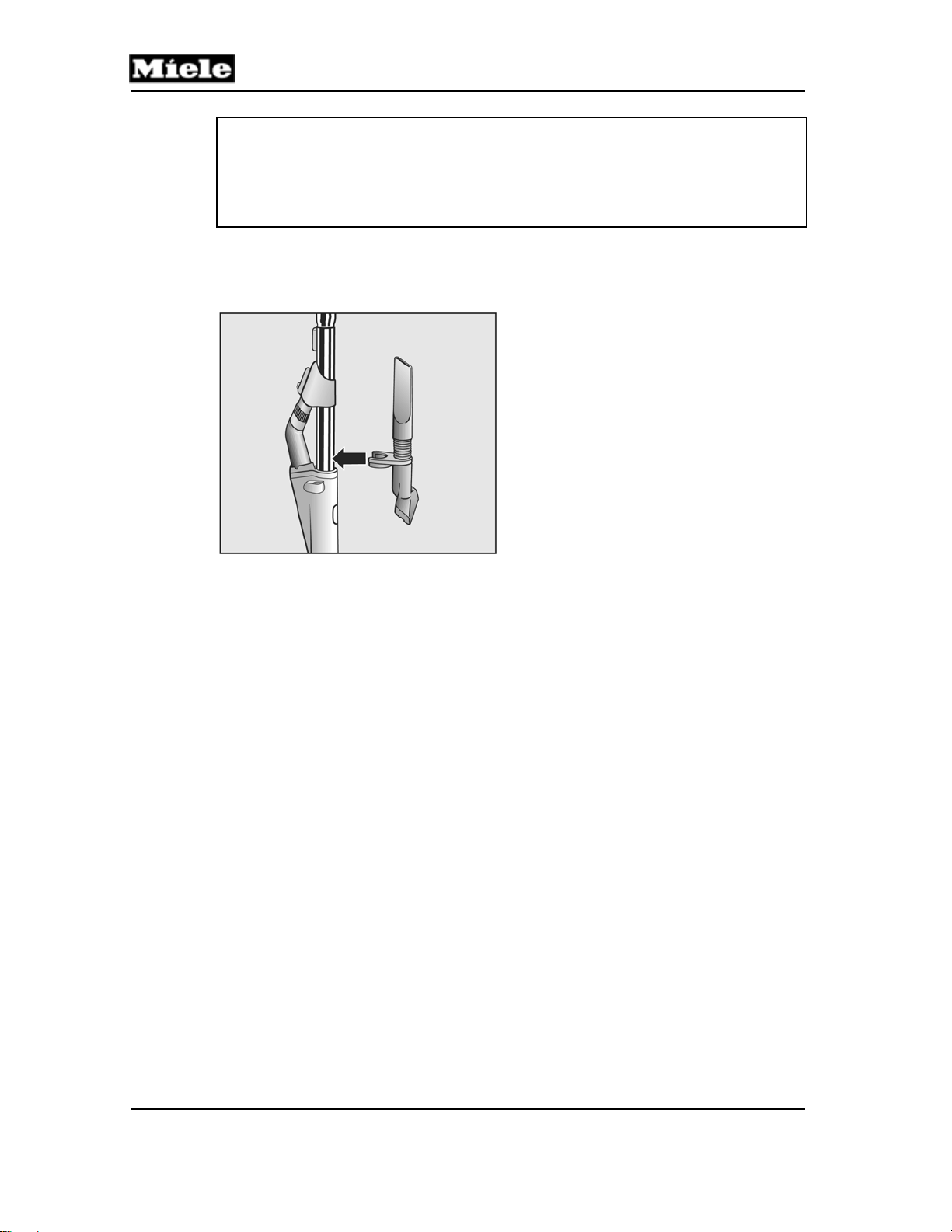
Figure D-7: Accessory Holder .......................................................................................... 16
Figure 010-1: Overheat Indicator ...................................................................................... 18
Figure 010-2: Filter Types ................................................................................................ 18
Figure 010-3: Storage Slot Removal ................................................................................ 19
Figure 010-4: Seal and Sealing Ring Removal ................................................................ 20
Figure 010-5: Levering Out the Support Roller ................................................................. 20
Figure 010-6: Bag Holder Removal .................................................................................. 21
Figure 010-7: Spring Position ........................................................................................... 21
Figure 010-8: Changing the Bag ...................................................................................... 22
Figure 010-9: Replacing the Super Air Clean Filter .......................................................... 22
Figure 010-10: Replacing the Active Air Clean or Active HEPA Filter .............................. 23
Figure 010-11: Removing/Inserting Grill ........................................................................... 23
Figure 010-12: Changing the Dust Compartment Filter .................................................... 24
Figure 010-13: Vacuum Pressure Monitor Removal ........................................................ 24
Figure 020-1: Turning the Adjustment Screw Clockwise .................................................. 26
Figure 020-2: Turning the Adjustment Screw Counterclockwise ...................................... 27
Figure 020-3: Shortening the Lid Catch Lugs ................................................................... 28
Figure 020-4: Accessory Compartment Lid Removal ....................................................... 29
Figure 020-5: Casing Top Removal .................................................................................. 29
Figure 020-6: Casing Top Installation ............................................................................... 30
Figure 020-7: Cover Frame Screws ................................................................................. 31
Figure 020-8: Dust Channel Holder Screws ..................................................................... 32
Figure 020-9: Connection Piece Removal ........................................................................ 33
Figure 020-10: Slide Sleeve and Dust Channel Pre-Assembly ........................................ 34
Figure 020-11: Slide Sleeve and Dust Channel Installation ............................................. 34
Figure 020-12: Bending the Slide Shutter ........................................................................ 35
Figure 020-13: Installing the Slide Shutter ....................................................................... 35
Figure 020-14: Releasing the Catch ................................................................................. 36
Figure 020-15: Spring Position (S 500 Models) ................................................................ 36
Figure 020-16: Spring Position (S 600 Models) ................................................................ 37
Figure 020-17: Cover Strip Removal ................................................................................ 37
Figure 020-18: Removing the Cover Strip from Its Guide ................................................ 38
Figure 020-19: Hinge Removal ......................................................................................... 38
Figure 020-20: Cord Guide with Cover Removal .............................................................. 39
Figure 020-21: Hinge Removal through Casing Top Opening ......................................... 39
Figure 020-22: Built-In Socket Installation ........................................................................ 40
Figure 020-23: Slide Sleeve Installation ........................................................................... 40
Figure 020-24: Install the Cover on the Cord Guide ......................................................... 41
Figure 020-25: Laying the Wires in the Cord Guide ......................................................... 41
Figure 030-1: Electronic Connections .............................................................................. 46
Figure 030-2: Direct-Connect Hose Connection ............................................................... 47
4
Page 5

500 & S 600 Canister Vacuums
Technical Information
Figure 030-3: Direct-Connect Hinge Connections ............................................................ 47
Figure 030-4: Electronic (Side View) ................................................................................ 48
Figure 030-5: Electronic (Top View) ................................................................................. 48
Figure 030-6: Cap Removal ............................................................................................. 49
Figure 030-7: Cap Installation .......................................................................................... 49
Figure 030-8: Cord Reel Removal .................................................................................... 50
Figure 030-9: Cord Reel, Unwound .................................................................................. 51
Figure 030-10: Cord Reel Clamped to Reel Assembly Body ........................................... 51
Figure 030-11: Screws Securing Cord Reel ..................................................................... 51
Figure 030-12: Cord Reel Tabs ........................................................................................ 52
Figure 030-13: Levering Out the Foot Switch ................................................................... 53
Figure 030-14: Plug Housing Removal ............................................................................. 53
Figure 030-15: Potentiometer & Indicator Light Removal (S 51x) .................................... 54
Figure 030-16: Plug Housing (S51x) ................................................................................ 54
Figure 030-17: Indicator Light and Bracket (S 52x, S 62x) ............................................... 55
Figure 030-18: Plug Housing (S 52x, S 62x) .................................................................... 56
Figure 030-19: Position of Gear Rack and Cog Wheel (S 52x, S 62x) ............................. 56
Figure 030-20: Gear Rack Removal (S 52x, S 62x) ......................................................... 57
Figure 030-21: Park System Switch Removal .................................................................. 57
Figure 040-1: Motor Removal ........................................................................................... 59
Figure 040-2: Carbon Brushes and Electronic ................................................................. 60
List of Tables
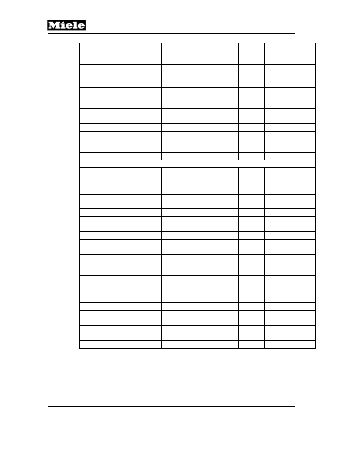
Table C-1: S 51x, S 52x and S 53x Data Sheet ................................................................. 8
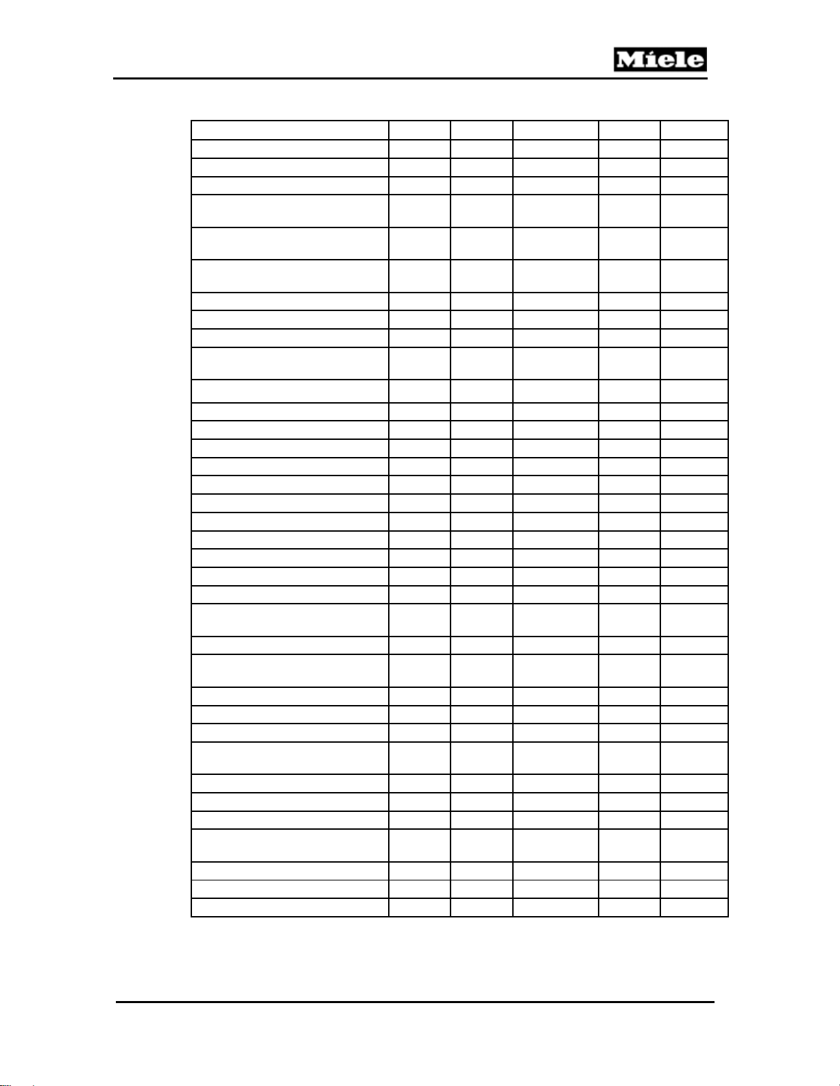
Table C-2: S 54x, S 55x, S 62x and S 65x Data Sheet .................................................... 10
5
Page 6
S 500 & S 600 Canister Vacuums
Technical Information
A Warning and Safety Instructions
1 General Information
All repairs should be performed by a trained technician in strict accordance
with national, state and local codes. Any repairs or maintenance performed
by unqualified personnel could be dangerous.
When servicing, modifying, testing or maintaining appliances, all applicable
laws, regulations and accident prevention guidelines must be observed.
All regulations of the appropriate utility supply companies and standards
relating to safety (not limited to electrical safety) are to be complied with.
Before any service work is started, the vacuum cleaner must be
disconnected from the power supply.
Even with the vacuum switched off, supply voltage may be applied to
some components.
Do not leave the vacuum unattended when it is plugged in. Turn off and
unplug the vacuum before opening the cover.
After work has been completed, a visual as well as an operational check
should always be performed.
2 Cleaning and Care
2.1 Vacuums and Accessories
The vacuum cleaner and other plastic components can be cleaned using a
damp cloth or a cleaner made especially for plastics.
Warning!
Do not use abrasive, glass or all-purpose cleaning solutions, as these can
cause considerable damage to the plastic components of the vacuum or its
accessories.
2.2 Dust Compartment
The dust compartment can be cleaned using another vacuum, if available, or a
dry cloth or brush.
Monitor the bag change indicator and inspect all filters regularly. Replace them
when necessary according to the maintenance instructions.
6
Page 7
500 & S 600 Canister Vacuums
B Modification History
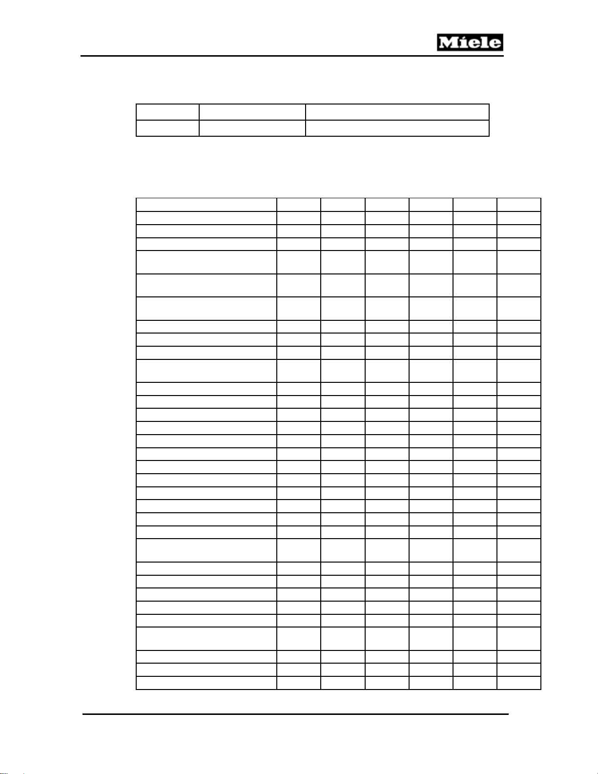
When? Who? What?
8/17/2011 Jessica Naples Compilation for Website
C Technical Data
Model S 514 S 516 S 518 S 524 S 528 S 538
Weight [lbs] 20.9 17.4 17.4 17.4 17.4 17.4
Radius of operation [ft] 36 36 36 36 36 36
Bag capacity (qts) 4.2 4.2 4.2 4.2 4.2 4.2
Required clearance with furniture
depth of 24”
Required clearance with furniture
depth of 40”
Non-vacuumed gap at skirting
board
Right 0.0” 0.0” 0.0” 0.0” 0.0” 0.0”
Left 0.0” 0.0” 0.0” 0.0” 0.0” 0.0”
Front 0.7” 0.7” 0.7” 0.7” 0.7” 0.7”
Operating width of floor
attachment
Suction power adjustment
Mechanical Yes Yes Yes Yes Yes Yes
Electronic Yes Yes Yes Yes Yes Yes
Automatic No No No No No No
On/off switch for Park System No No Yes Yes Yes Yes
Bag type M M F/J/M M M M
Textile bag No No No No No No
Super Air Clean filter Yes No No Yes No Yes
Active Air Clean filter No Yes Yes No Yes No
HEPA filter No No No No No No
Active HEPA filter No No No No No No
Bag change indicator Yes Yes Yes Yes Yes Yes
Electric exhaust filter change
indicator
Overheating indicator light Yes Yes Yes Yes Yes Yes
Exhaust plate / Filter grille No/Yes No/Yes No/Yes No/Yes No/Loose No/Yes
Hygienic slide shutter Yes Yes Yes Yes Yes Yes
Automatic cord rewind Yes Yes Yes Yes Yes Yes
Autoreverse function No No No No No No
Connection for electrical
attachment
Telescopic suction tube/handle Yes/No Yes/No Yes/No Yes/No Yes/No Yes/No
2-part sectioned suction tube No No No No No No
Suction tube holder Yes Yes Yes Yes Yes Yes
2.8” 2.8” 2.8” 2.8” 2.8”
2.8”
2.8” 2.8” 2.8” 2.8” 2.8”
2.8”
11.0” 11.0” 11.0” 11.0” 11.0”
11.0”
No No No No No Yes
Yes No Yes Yes
Technical Information
Yes Yes
7
Page 8
Technical Information
Model S 514 S 516 S 518 S 524 S 528 S 538
Electrical/Mechanical brush
attachments
Suction hose Yes Yes Yes Yes Yes Yes
Universal floor attachment Yes Yes Yes Yes Yes Yes
Upholstery nozzle/ Dusting brush Yes/Yes Yes/Yes Yes/Yes Yes/Yes Yes/Yes Yes/Yes
Crevice nozzle/ Extended crevice
nozzle
Accessory storage on/in unit No/Yes No/Yes No/Yes No/Yes No/Yes No/Yes
Power rating 1100W 1100W 1100W 1100W 1100W 1100W
Voltage 120V 120V 120V 120V 120V 120V
Fuse rating 15A 15A 15A 15A 15A 15A
Complies with German safety
regulations
Interference suppression Yes Yes Yes Yes Yes Yes
Operating instructions Yes Yes Yes Yes Yes Yes
Optional extras available at additional charge
Electrobrush SEB 216 with clip
cord
Electrobrush SEB 217with direct
contact
Hand turbobrush STB
101 TURBO MINI
Turbobrush STB 205 Yes Yes Yes Yes Yes Yes
Floor brush SBB 235 Yes Yes Yes Yes Yes Yes
Floor brush Parquet/Parquet-2 Yes Yes Yes No No No
Multi-purpose brush No No No Yes Yes Yes
MicroSet Yes Yes Yes
CarClean Set Plus Yes Yes Yes
Universal floor brush/ Natural-
bristle dusting brush
Mattress brush/ Radiator brush Yes/Yes Yes/Yes Yes/Yes Yes/Yes Yes/Yes Yes/Yes
Upholstery nozzle/ Dusting brush
Crevice nozzle (300mm)/Extended
crevice nozzle
Textile filter bag
Super Air Clean filter Supplied Supplied Yes Supplied Yes Supplied
Active Air Clean filter Yes Yes Supplied Yes Supplied Yes
HEPA filter No No No No No No
Active HEPA filter Yes Yes Yes Yes Yes Yes
Suction hose extension No No Yes No No No
Table C-1: S 51x, S 52x and S 53x Data Sheet
S 500 & S 600 Canister Vacuums
Yes/No No/No No/No No/No No/No No/No
Yes/No Yes/No Yes/No Yes/No Yes/No
Yes/No
Yes Yes Yes Yes Yes
Yes
Supplied No No Yes
No No No No No No
Yes Yes Yes Yes
Yes/Yes Yes/Yes Yes/Yes Yes/Yes Yes/Yes Yes/Yes
Supplied/
Supplied
Supplied/
Yes
No No No
Supplied/
Supplied
Supplied/
Yes
Supplied/
Supplied
Yes/Yes
Yes Yes
Yes Yes
Yes
Yes Yes
Yes
Yes Yes
Supplied/
Supplied
Supplied/
Yes
No No No
Supplied/
Supplied
Supplied/
Yes
Supplied/
Supplied
Supplied/
Yes
8
Page 9
500 & S 600 Canister Vacuums
Model S 544 S 548 S 558 S 624 S 658
Weight [lbs] 17.4 17.4 24.0 19.6 26.2
Radius of operation [ft] 36 36 36 43 43
Bag capacity (qts) 4.2 4.2 4.2 6.1 6.1
Required clearance with furniture
depth 24”
Required clearance with furniture
depth 40”
Non-vacuumed gap at skirting
board
Right 0.0” 0.0” 0.0” 0.0” 0.0”
Left 0.0” 0.0” 0.0” 0.0” 0.0”
Front 0.7” 0.7” 0.7” 0.7” 0.7”
Operating width of floor
attachment
Suction power adjustment
Mechanical Yes Yes No Yes No
Electronic Yes Yes On handle Yes On handle
Automatic Yes Yes No No No
On/off switch for Park System Yes Yes No Yes No
Bag type M M M N N
Textile bag No No No No No
Super Air Clean filter Yes No No Yes No
Active Air Clean filter No No No No No
HEPA filter No No No No No
Active HEPA filter No Yes Yes No Yes
Bag change indicator Yes Yes Yes Yes Yes
Electric exhaust filter change
indicator
Overheating indicator light Yes Yes Yes Yes Yes
Exhaust plate / Filter grille No/Yes No/Loose No/Loose
Hygienic slide shutter Yes Yes Yes Yes Yes
Automatic cord rewind Yes Yes Yes Yes Yes
Autoreverse function Yes Yes Yes No Yes
Connection for electrical
attachment
Telescopic suction tube/handle Yes/No Yes/No Electro-/No Yes/No Electro-/No
2-part sectioned suction tube No No No No No
Suction tube holder Yes Yes Yes Yes Yes
Electrical/Mechanical brush
attachments
Suction hose Yes Yes Yes Yes Yes
Universal floor attachment Yes Yes Yes Yes Yes
Upholstery nozzle/ Dusting brush Yes/Yes Yes/Yes Yes/Yes Yes/Yes Yes/Yes
Technical Information
2.8” 2.8” 2.8” 2.8”
2.8”
2.8” 2.8” 2.8” 2.8”
2.8”
11.0” 11.0” 11.0” 11.0”
11.0”
Yes Yes No Yes
Yes
Loose/
Yes
Yes Yes Yes Yes
Yes
No/No No/No Yes/No No/No Yes/No
Loose/
Loose
9
Page 10
Technical Information
Model S 544 S 548 S 558 S 624 S 658
Crevice nozzle/ Extended crevice
nozzle
Accessory storage on/in unit No/Yes No/Yes No/Yes No/Yes No/Yes
Power rating 1100W 1100W 1100W 1100W 1100W
Voltage 120V 120V 120V 120V 120V
Fuse rating 15A 15A 15A 15A 15A
Complies with German safety
regulations
Interference suppression Yes Yes Yes Yes Yes
Operating instructions Yes Yes Yes Yes Yes
Optional extras available at additional charge
Electrobrush SEB 216 with clip
cord
Electrobrush SEB 217 with direct
contact
Hand turbobrush STB
101 TURBO MINI
Turbobrush STB 205 Yes Yes Yes Yes Yes
Floor brush SBB 235 Yes Yes Yes Yes1 Yes
Multi-purpose brush Yes Yes Yes Yes Supplied
Upholstery nozzle/ Dusting brush
Crevice nozzle/ Extended crevice
nozzle
Textile filter bag No No No No No
Suction hose extension No No No No Yes
Super Air Clean filter Yes Yes Yes Supplied Yes
Active Air Clean filter Yes Yes Yes Yes No
HEPA filter No No No No Supplied
Active HEPA filter No Supplied Supplied Yes No
Table C-2: S 54x, S 55x, S 62x and S 65x Data Sheet
1
Supplied for Parquet models.
S 500 & S 600 Canister Vacuums
Yes/No Yes/No Yes/No
Yes Yes Yes Yes
Yes
Yes No Yes Supplied
Yes
No No Supplied No Yes
Yes Yes Yes Yes
Yes
Supplied/
Supplied
Supplied/
Yes
Supplied/
Supplied
Supplied/
Yes
Yes/Yes Yes/Yes
Supplied/
Supplied
Supplied/Yes
Supplied/
Supplied
Supplied/
Supplied
Supplied/
Supplied
No
10
Page 11
500 & S 600 Canister Vacuums
D Layout of Electrical Components
1 S 51x Models
Technical Information
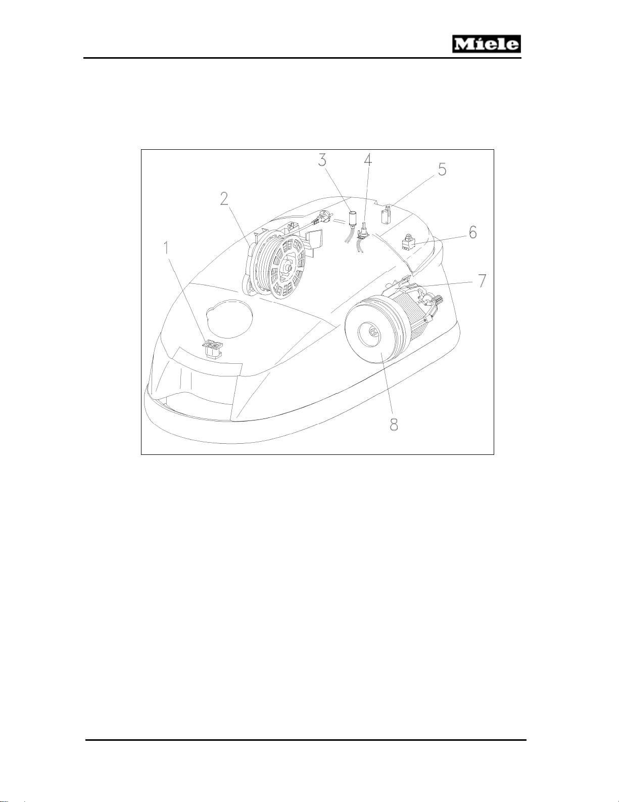
Figure D-1: S 51x Component Layout
1
Accessory socket X1/7
2
Cord reel W16
3
Fault indicator H1/3
4
Motor speed control potentiometer R32/1
5
Park System switch Q2 (not US models)
6
Main switch Q1
7
Motor electronic N2
8
Motor M2
11
Page 12
Technical Information
2 S 52x and S 53x Models
S 500 & S 600 Canister Vacuums
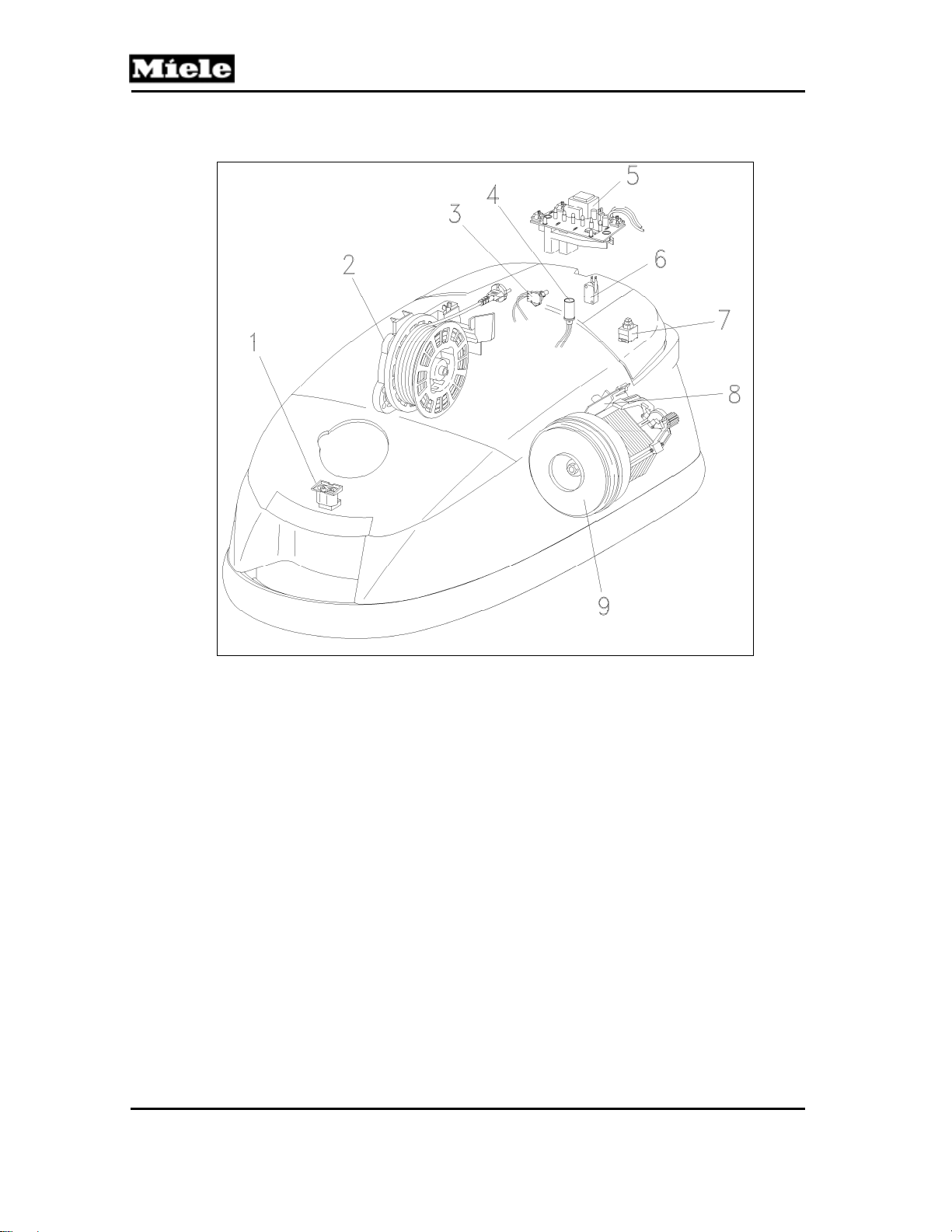
Figure D-2: S 52x and S 53x Component Layout
1
Accessory socket X1/7
2
Cord reel W16
3
Motor speed control potentiometer R32/1
(S 52x only)
4
Fault indicator H1/3
5
Electronic control 1N1 (not US models)
6
Park System switch Q2
7
Main switch Q1
8
Motor electronic 1N2
9
Motor M2
12
Page 13
500 & S 600 Canister Vacuums
3 S 54x and S 55x Models
Technical Information
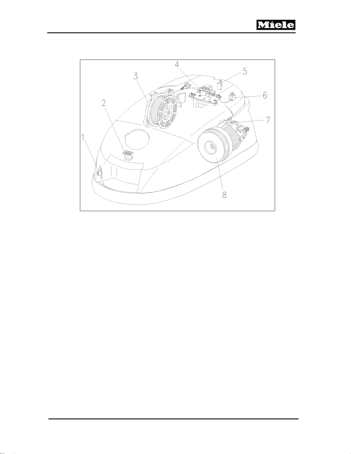
Figure D-3: S 54x and S 55x Component Layout
1
Vacuum pressure monitor B9/2
(S 544, S 548 only)
2
Accessory socket X1/7
3
Cord reel W16
4
Electronic control 1N1
5
Park System switch Q2
6
Main switch Q1
7
Motor electronic 1N2
8
Motor M2
13
Page 14
Technical Information
4 S 62x Models
S 500 & S 600 Canister Vacuums
Figure D-4: S 62x Component Layout
1
Accessory socket X1/7
2
Cord reel W16
3
Motor speed control potentiometer R32/1
4
Fault indicator H1/3
5
Electronic control 1N1 (not US models)
6
Park System switch Q2
7
Main switch Q1
8
Electronic power control 1N2
9
Motor M2
14
Page 15
500 & S 600 Canister Vacuums
5 S 65x Models
Technical Information
Figure D-5: S 65x Component Layout
1
Vacuum pressure monitor B9/2
(not US models)
2
Accessory socket X1/7
3
Cord reel W16
4
Electronic control 1N1
6 Accessories
The items shown in Figure D-6 are included with the vacuum cleaner.
Figure D-6: Accessories
5
Park System switch Q2
6
Main switch Q1
7
Electronic power control 1N2
8
Motor M2
1 Accessory adapter
2 Crevice nozzle
3 Upholstery tool
4 Filter frame
15
Page 16
Technical Information
Note:
The filter frame is only supplied with select models fitted with an Active Air
Clean or HEPA exhaust filter as standard. This filter frame is required
should the customer wish to replace one of these filters with a Super Air
Clean filter.
6.1 Accessory Holder
The accessory holder (Figure D-7) stores the accessories on the vacuum
cleaner.
S 500 & S 600 Canister Vacuums
Figure D-7: Accessory Holder
16
Page 17
500 & S 600 Canister Vacuums
010 Casing Bottom
Technical Information
17
Page 18
Technical Information
2 Function
2.1 Dustbags
A clean bag is essential to the maximum efficiency of the vacuum. A clogged
bag can cause restricted airflow resulting in poor suction or, in extreme cases,
an overheat condition can occur resulting in the vacuum shutting off. An
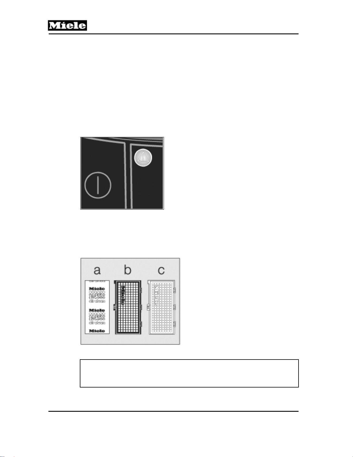
ORANGE indicator light next to the tool access button identifies a bag filled to
capacity. An overheat condition is identified by a TRIANGULAR LIGHT on the
control panel. See Figure 010-1. Changing the bag is relatively easy; the most
important thing to remember is to use the correct bag. A list of dustbags and
the models in which they are used can be found in the product line information
in the operating manual.
S 500 & S 600 Canister Vacuums
Figure 010-1: Overheat Indicator
2.2 Filters
Miele canister vacuums use several types of filters (Super Air Clean, Active Air
Clean, Active HEPA) to provide a clean, healthy environment. See Figure 010-
2. Vacuum model will dictate filter(s) type; refer to Tables C-1 and C-2.
Figure 010-2: Filter Types
Note:
Changing from one type of filter to another type is permitted. (e.g., Active Air
Clean to Active HEPA). See Section 010-4.9 for instructions.
a Super Air Clean
b Active Air Clean
c Active HEPA (High Efficiency Particulate Air)
18
Page 19
500 & S 600 Canister Vacuums
4 Service
4.1 Storage Slot Removal
1. Remove the casing top. See Section 020-4.2.
2. Remove the cap. See Section 030-4.1.
3. Remove the cover frame. See Section 020-4.5.
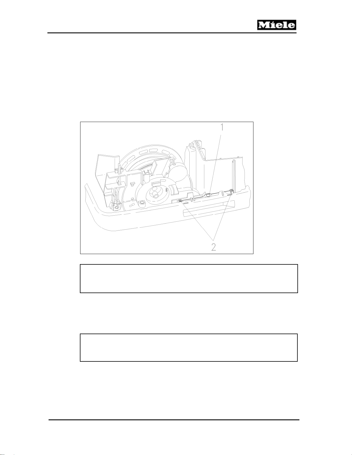
4. Remove the retaining screw (Figure 010-3, Item 1) from the storage slot.
5. Remove the storage slot with bumper strip from its holder; see Figure 010-3,
Item 2.
6. Remove the storage slot from the bumper strip.
Technical Information
Figure 010-3: Storage Slot Removal
Note:
When re-installing, ensure that the storage slot and the bumper strip are
seated correctly.
4.2 Bumper Strip Removal
1. Remove the storage slot. See Section 010-4.1.
2. Remove the handle strip.
3. Remove the bumper strip.
Note:
When re-installing, ensure that the bumper strip (and storage slot) are
seated correctly.
4.3 Seal and Sealing Ring Removal
1. Remove the casing top. See Section 020-4.2.
2. Remove the cap. See Section 030-4.1.
3. Remove the cover frame. See Section 020-4.5.
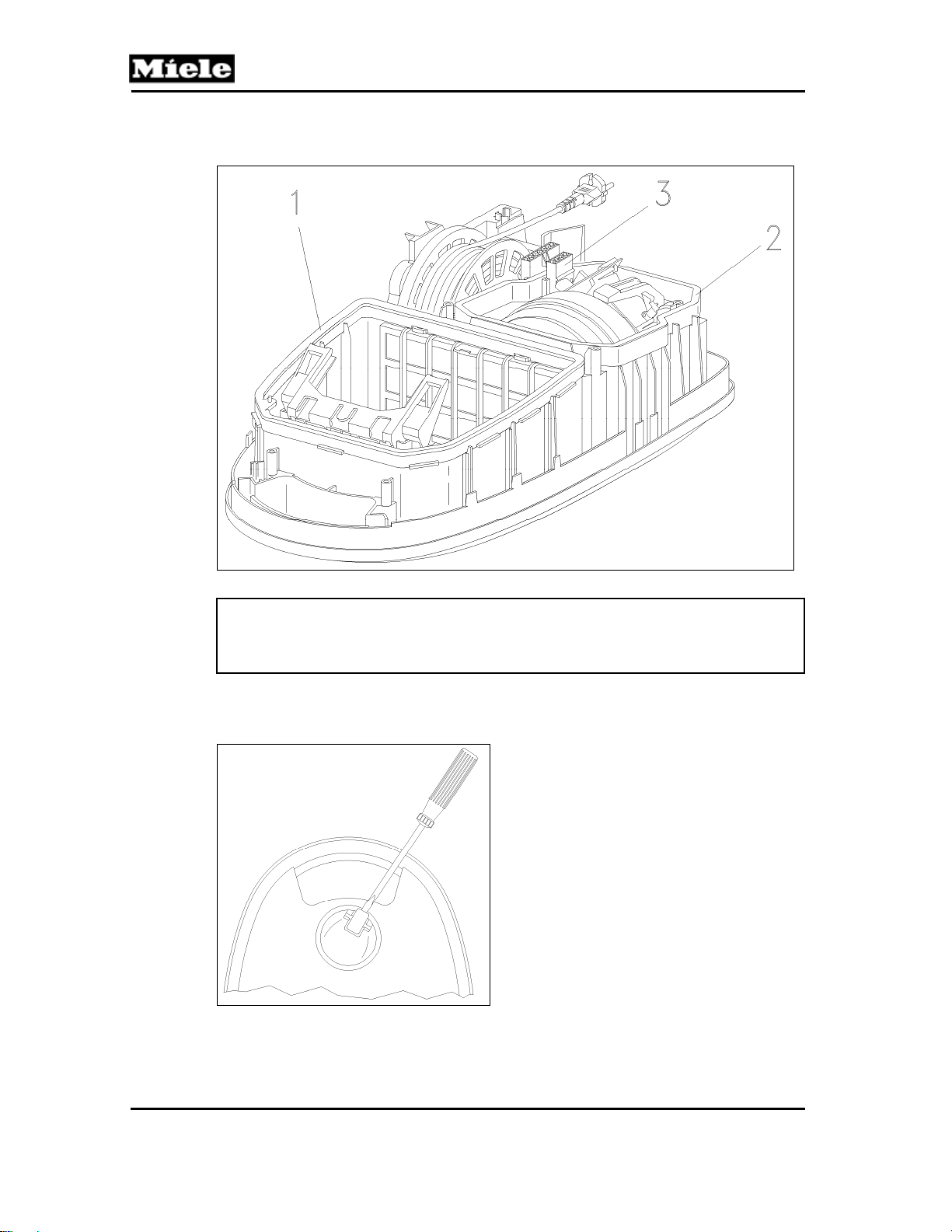
4. Remove the motor wiring harness (Figure 010-4, Item 3) from its holder.
19
Page 20
Technical Information
5. Remove the seal (Figure 010-4, Item 2) and sealing ring (Figure 010-4,
Item 1).
S 500 & S 600 Canister Vacuums
Figure 010-4: Seal and Sealing Ring Removal
Note:
When re-installing, ensure that the seal and sealing ring are seated
correctly.
4.4 Caster Removal
1. Lever out the support roller with a screwdriver. See Figure 010-5.
Figure 010-5: Levering Out the Support Roller
2. Remove the 2 shaft screws.
20
Page 21
500 & S 600 Canister Vacuums
4.5 Bag Holder Removal
1. Open the casing top.
2. Remove the bag.
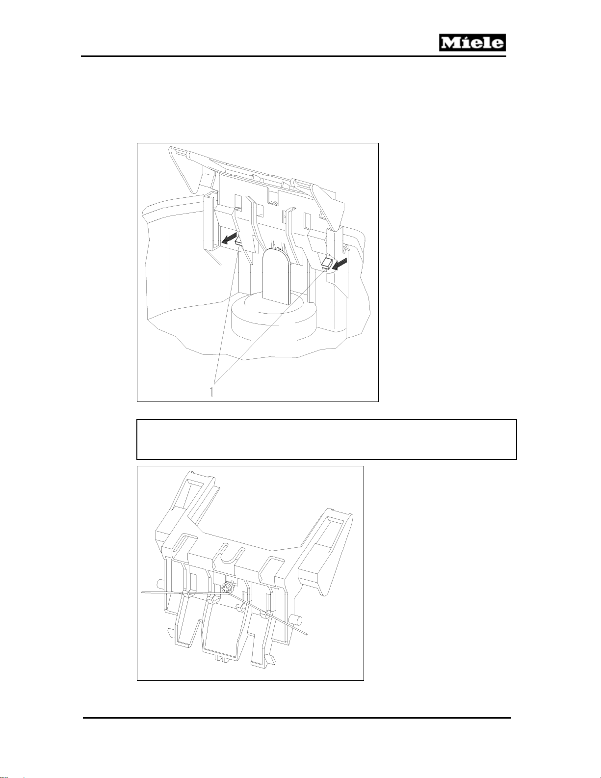
3. Press the 2 tabs out of the way and remove the bag holder. See Figure
010-6, Item 1.
Technical Information
Figure 010-6: Bag Holder Removal
Note:
When installing, the spring must rest on the outer retainers. See Figure 010-7.
Figure 010-7: Spring Position
21
Page 22
Technical Information
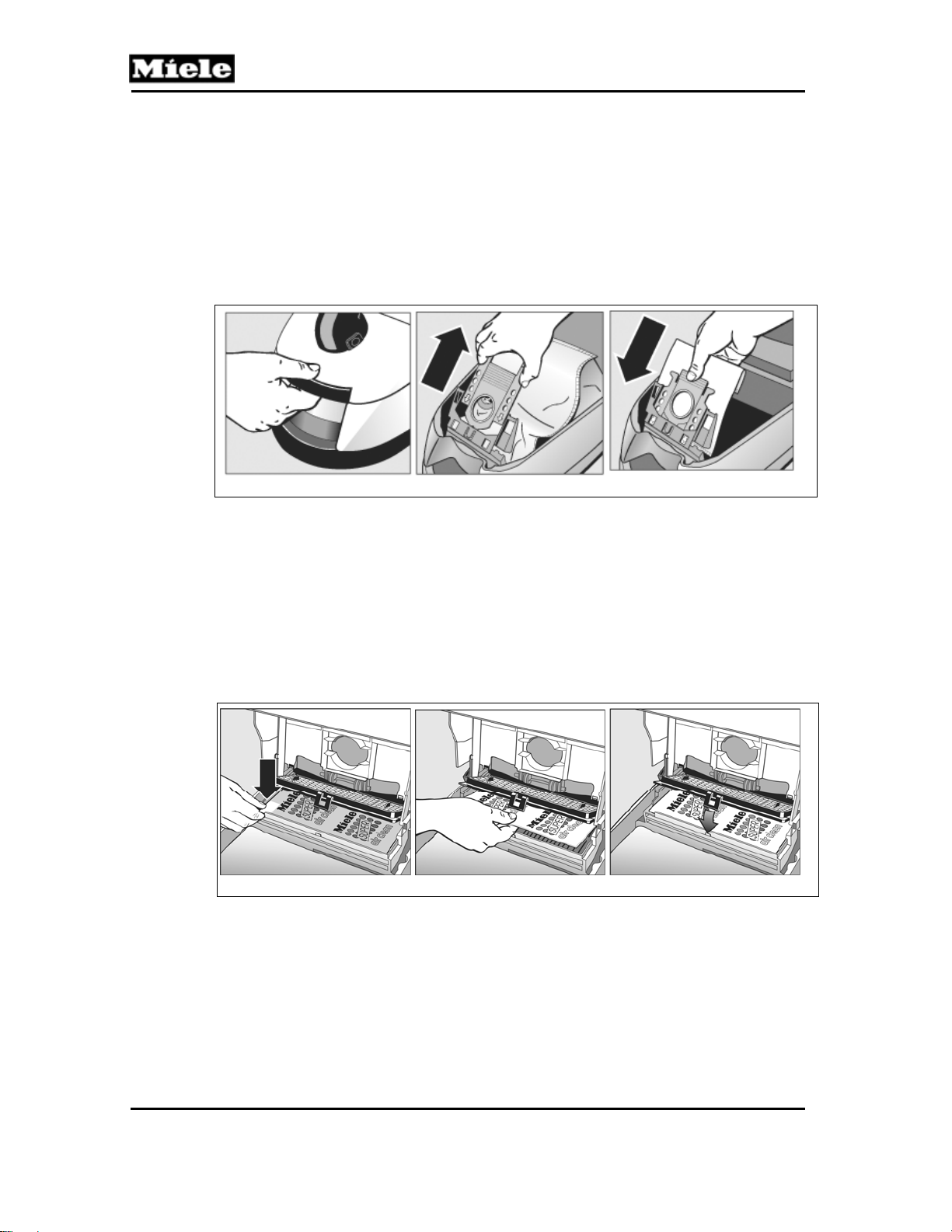
4.6 Changing the Bag
1. Open the lid. See Figure 010-8, Item 1.
2. Grasp the bag using the two finger holes and pull up (see Figure 010-8,
Item 2). Doing so automatically closes the bag cover, preventing debris
and dust from escaping from the bag.
3. Discard the full bag in a suitable container (trash can).
4. Remove the NEW bag from the box. DO NOT UNFOLD IT.
5. Slide the tabs into the frame as far as it will go (Figure 010-8, Item 3).
6. Close the lid.
S 500 & S 600 Canister Vacuums
1 2 3
Figure 010-8: Changing the Bag
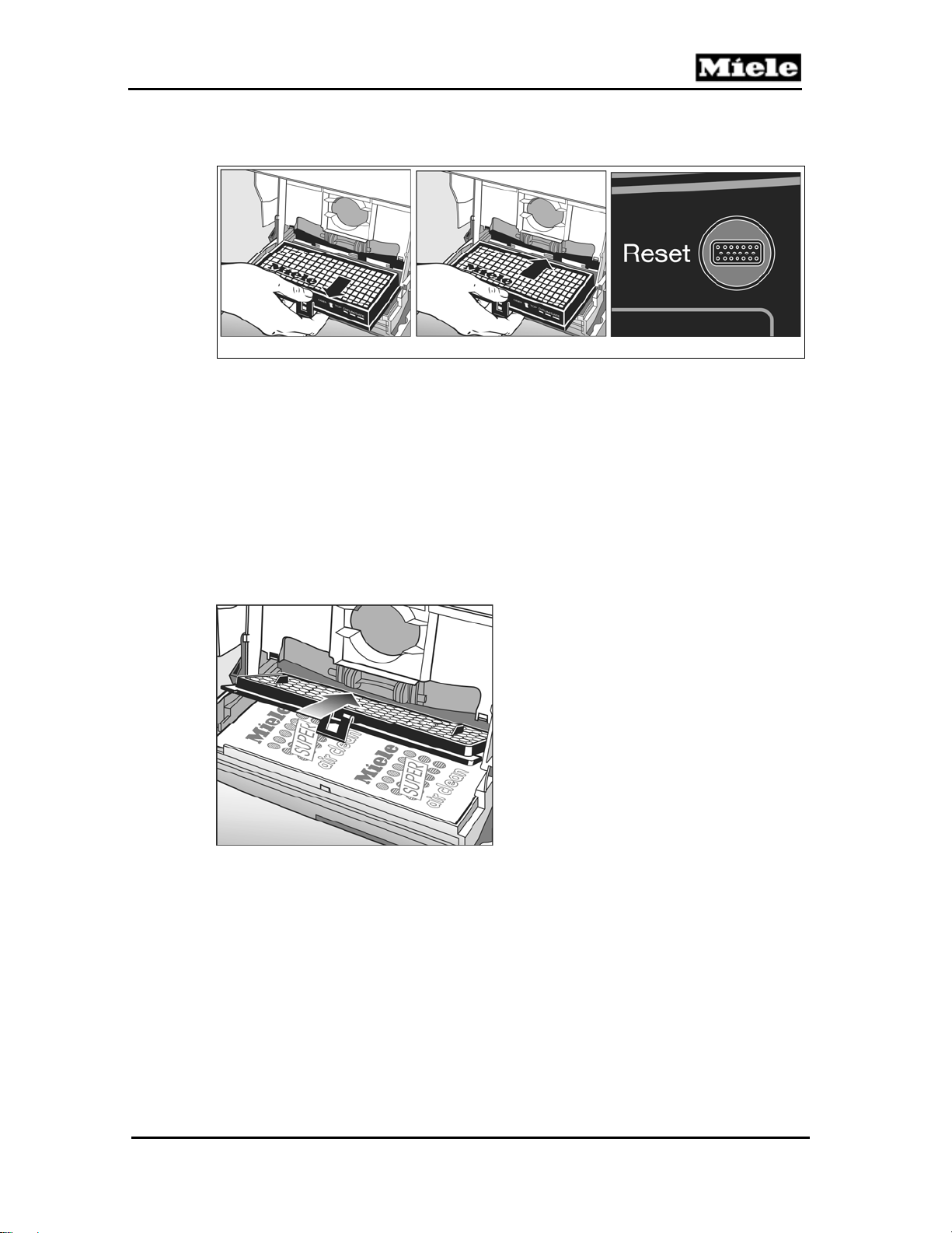
4.7 Replacing the Super Air Clean Filter
1. Release the filter grill and raise it up.
2. Carefully grasp the filter at an UNSOILED section and remove. See Figure
010-9, Item 1.
3. Replace with a new filter. It can be inserted either side up. See Figure 0109, Item 2.
4. Lower the grill and snap into place. See Figure 010-9, Item 3.
5. Close the dust compartment lid until it “CLICKS”.
1 2 3
Figure 010-9: Replacing the Super Air Clean Filter
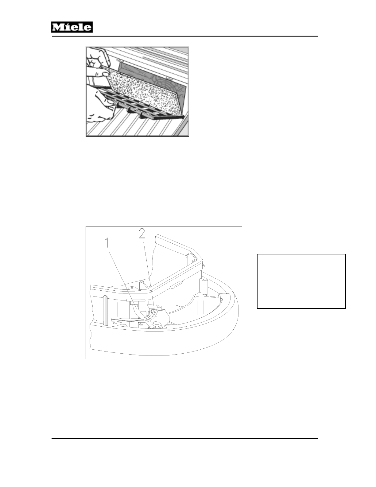
4.8 Replacing the Active Air Clean or Active HEPA Filter
1. Open the dust compartment lid.
2. Release the catch and remove the filter. See Figure 010-10, Item 1.
3. Insert the new filter so that it engages at the BACK and then close the
catch. See Figure 010-10, Item 2.
4. Close the dust compartment lid until it “clicks”.
22
Page 23
500 & S 600 Canister Vacuums
5. Remember to reset the filter change indicator by pressing it until it goes
out. See Figure 010-10, Item 3.
1 2 3
Figure 010-10: Replacing the Active Air Clean or Active HEPA Filter
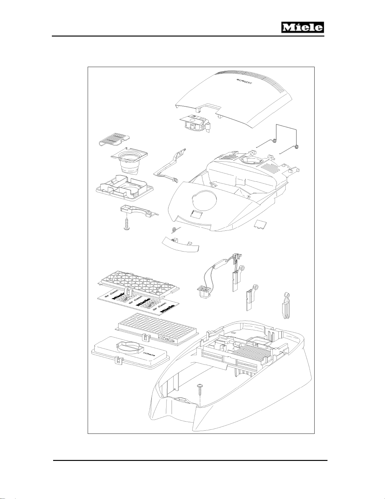
4.9 Replacing One Type of Filter with Another
If you wish to replace the SUPER CLEAN FILTER with the ACTIVE AIR
CLEAN FILTER or the ACTIVE HEPA FILTER, you MUST REMOVE the grill
BEFORE inserting the new type of filter. See Figure 010-11.
If you wish to replace the ACTIVE AIR CLEAN FILTER or the ACTIVE HEPA
FILTER with the SUPER CLEAN FILTER then you MUST ALSO INSERT the
grill.
Technical Information
The ACTIVE AIR CLEAN FILTER can be used instead of the ACTIVE HEPA
FILTER, or vice versa, without any changes.
Figure 010-11: Removing/Inserting Grill
4.10 Changing the Dust Compartment (Motor Protection) Filter
Replace the dust compartment filter every time a new box of dustbags is
started.
To change (refer to Figure 010-12):
1. Open the dust compartment.
2. Unclip the filter frame, remove the old filter and replace it with a new one.
3. Close the filter frame.
23
Page 24
Technical Information
S 500 & S 600 Canister Vacuums
Figure 010-12: Changing the Dust Compartment Filter
4.11 Vacuum Pressure Monitor Removal
1. Remove the casing top. See Section 020-4.2.
2. Remove the cap. See Section 030-4.1.
3. Remove the cover frame. See Section 020-4.5.
4. Lift the sealing ring at the vacuum pressure monitor.
5. Remove the hose (Figure 010-13, Item 1) from the sealing ring and the
vacuum pressure monitor.
6. Disconnect the plug connector (Figure 010-13, Item 2) and remove the
vacuum pressure monitor.
Note:
When re-installing, slide
the hose as far as
possible into the sealing
ring and onto the vacuum
pressure monitor.
Figure 010-13: Vacuum Pressure Monitor Removal
24
Page 25
500 & S 600 Canister Vacuums
020 Casing Top
Technical Information
25
Page 26
Technical Information
3 Fault Repair
3.1 Bag Change Indicator Reacts Too Late
Cause:
Coarse dirt (e.g., hair or carpet fluff) has been vacuumed.
Coarse dirt fills the bag quickly but does not clog its pores. A vacuum is not
developed and the bag change indicator only reacts when the bag is
absolutely full to the limit.
Remedy:
Replace the bag.
Cause:
The bag change indicator is set to mixed dust, but the composition of the dirt
taken into the vacuum cleaner does not come under the category of mixed
dust
Remedy:
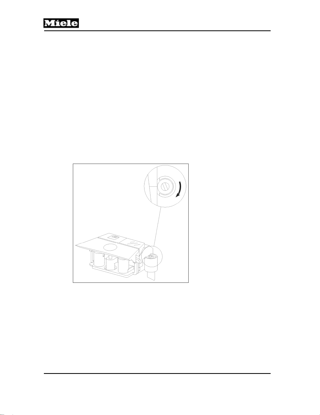
Turn the adjustment screw on the bag change indicator clockwise. (See Figure
020-1.) The indicator then reacts more quickly.
S 500 & S 600 Canister Vacuums
Figure 020-1: Turning the Adjustment Screw Clockwise
3.2 Bag Change Indicator Reacts Too Early
Cause:
Very fine dust (e.g., flour) has been vacuumed.
Fine dust clogs the bag pores immediately. The closed pores then allow a
vacuum to develop, which causes the bag change indicator to show that the
bag is full even though it is still empty.
Remedy:
Replace the bag.
26
Page 27
500 & S 600 Canister Vacuums
Cause:
The bag change indicator is set to mixed dust, but the composition of the dirt
taken into the vacuum cleaner does not come under the category of mixed
dust.
Remedy:
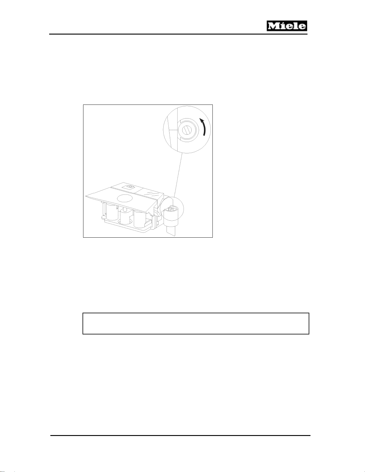
Turn the adjustment screw on the bag change indicator counterclockwise.
(See Figure 020-2.) The indicator then reacts later.
Technical Information
Figure 020-2: Turning the Adjustment Screw Counterclockwise
3.3 Accessory Compartment Lid Difficult to Close
Cause:
Lid catch is stiff.
Remedy:
1. Open the lid.
2. Apply a thin coating of Baysilone oil (mat. no. 1940430 or 2988840) to the
catch retaining hooks.
Note:
Use only silicone oil; other types of oil can damage plastic parts.
3.4 Accessory Compartment Lid Difficult to Open
Cause:
Lid catch tabs are too long.
Remedy:
1. Open the lid.
2. Pull out the lid catch upwards.
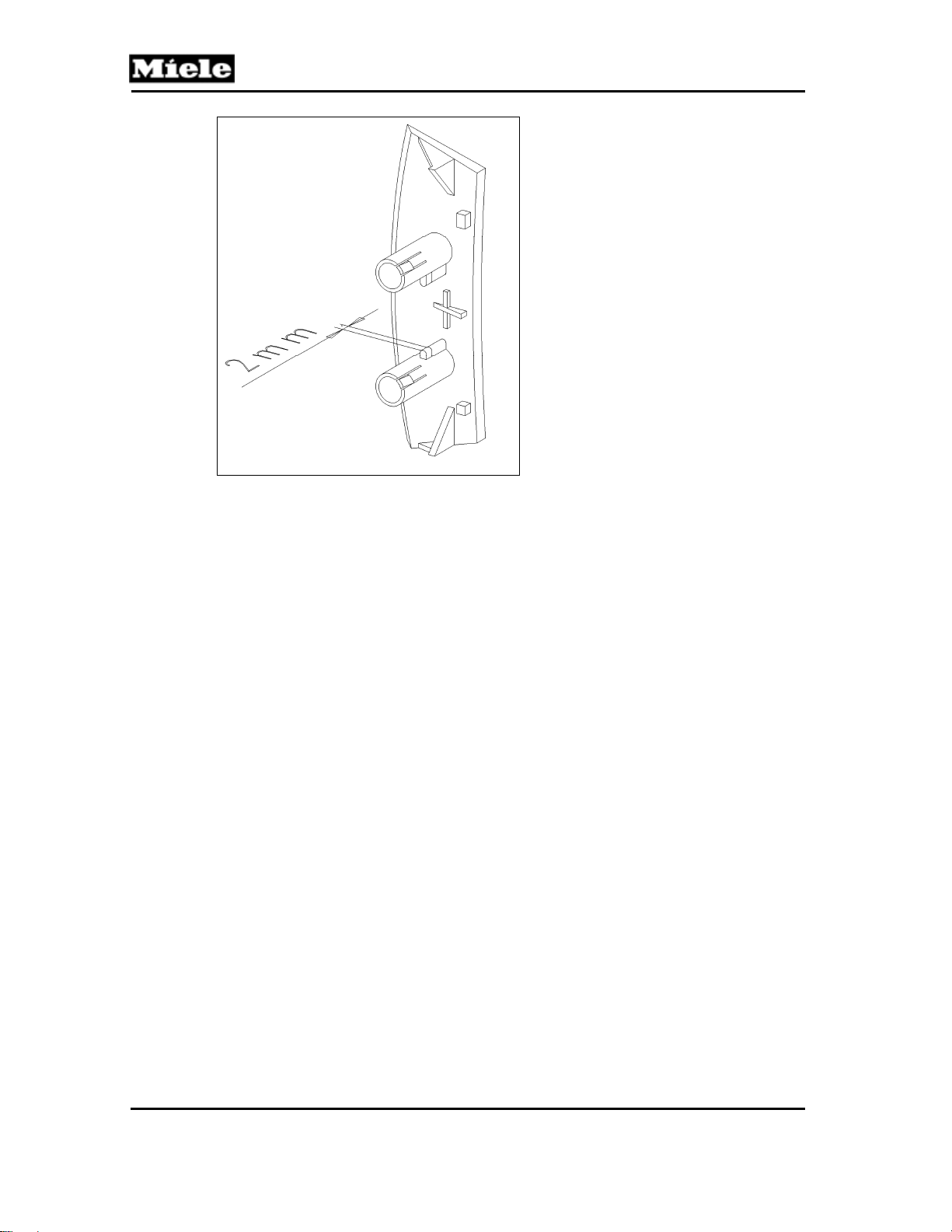
3. Shorten both tabs by approximately one tenth of an inch (2 millimeters)
with a suitable sharp knife; see Figure 020-3.
27
Page 28
Technical Information
S 500 & S 600 Canister Vacuums
Figure 020-3: Shortening the Lid Catch Lugs
3.5 Accessory Compartment Lid Rocks Back and Forth
Symptom:
Accessory compartment lid rocks back and forth when opened.
Cause:
The lid catch tabs are too short.
Remedy:
The casing top has been modified in the lid hinge area. This has improved the
accessory compartment lid guiding and prevents rocking back and forth.
Install new lid catch tabs, mat. no. 05407150.
4 Service
4.1 Accessory Compartment Lid Removal
1. Open the accessory compartment lid wide to its end stop.
2. Lever the lid free of the catch tabs (Figure 020-4, Item 1).
28
Page 29
500 & S 600 Canister Vacuums
Technical Information
Figure 020-4: Accessory Compartment Lid Removal
4.2 Casing Top Removal
1. Open the casing top wide to its end stop.
2. Remove the filter.
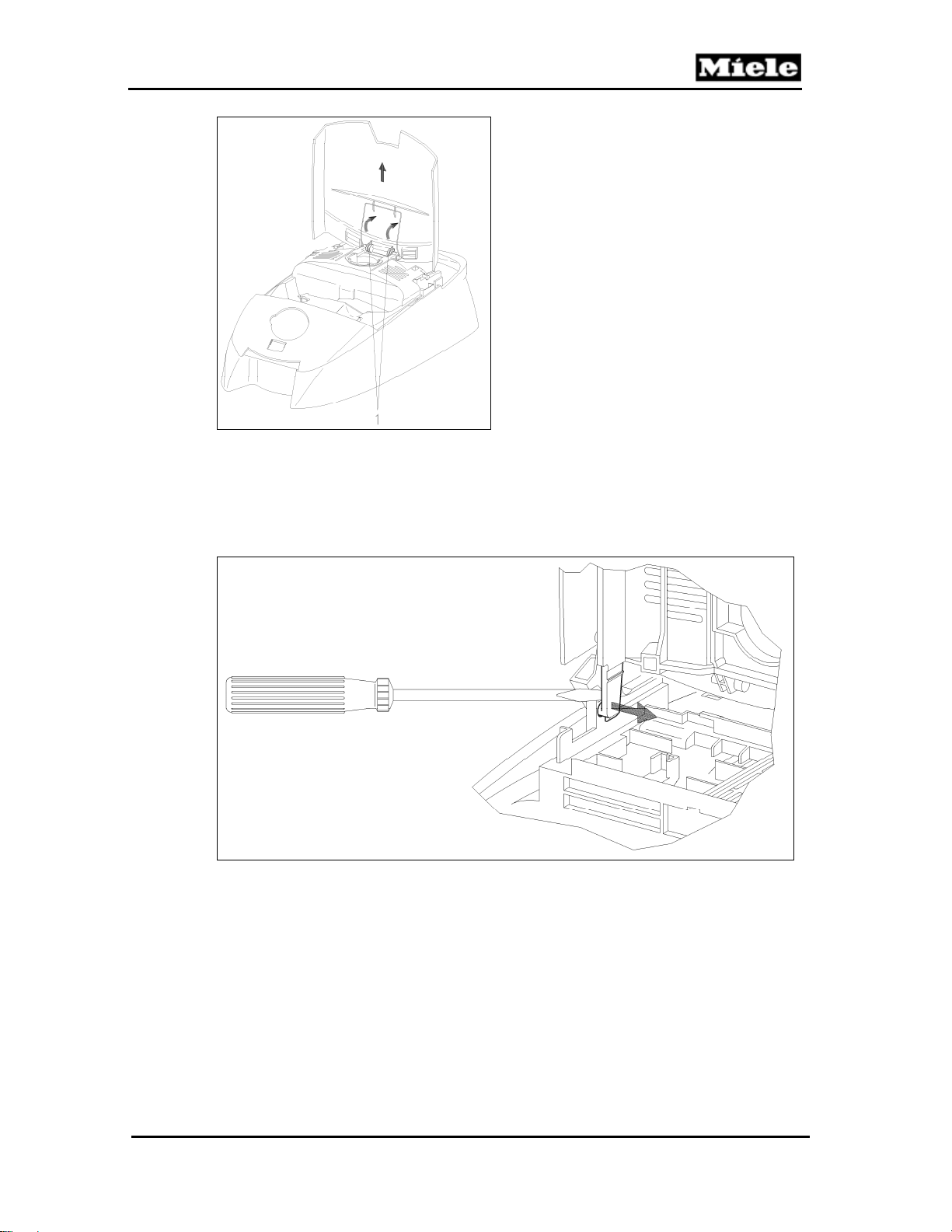
3. Use a screwdriver to lever the hinge arms free, Figure 020-5.
Figure 020-5: Casing Top Removal
29
Page 30
Technical Information
4.3 Casing Top Installation
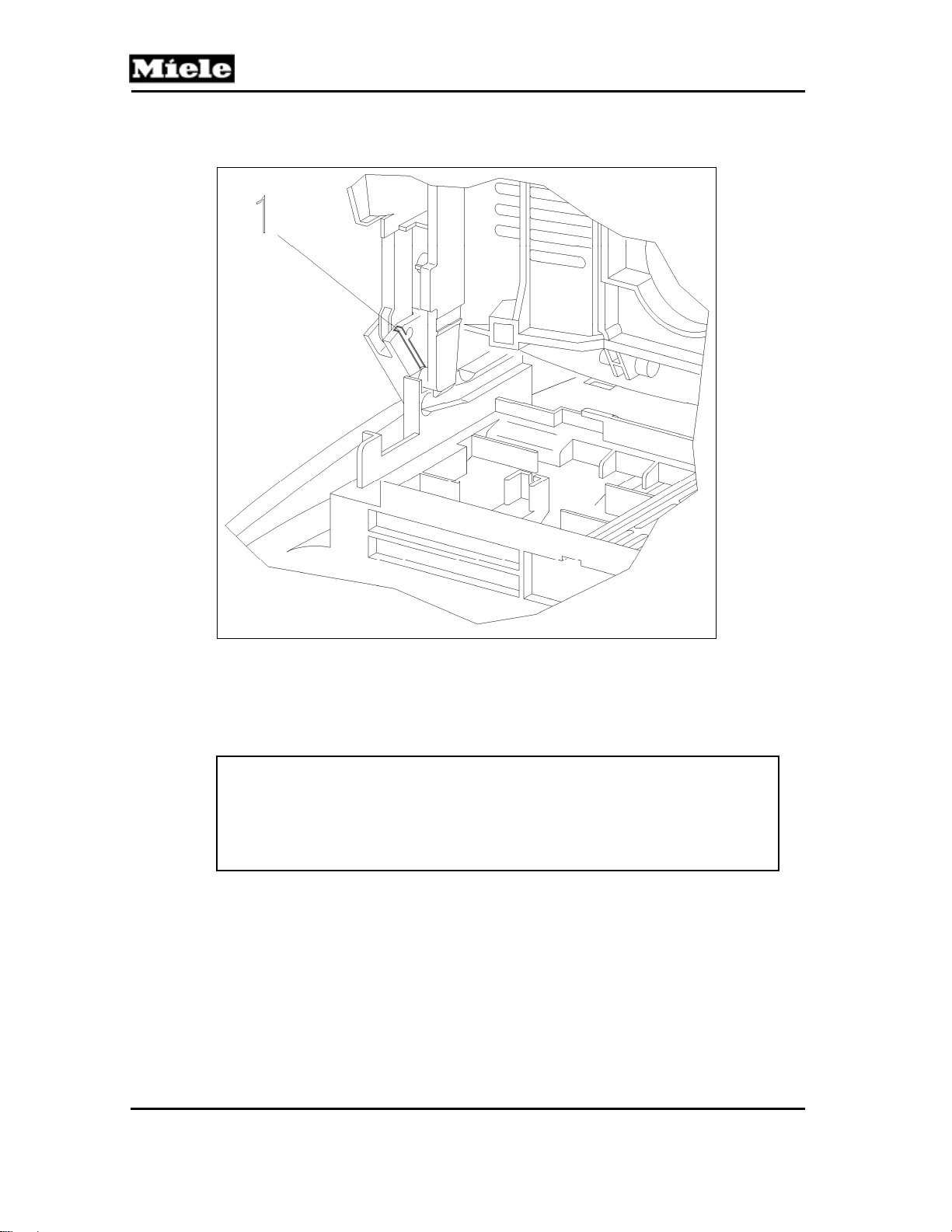
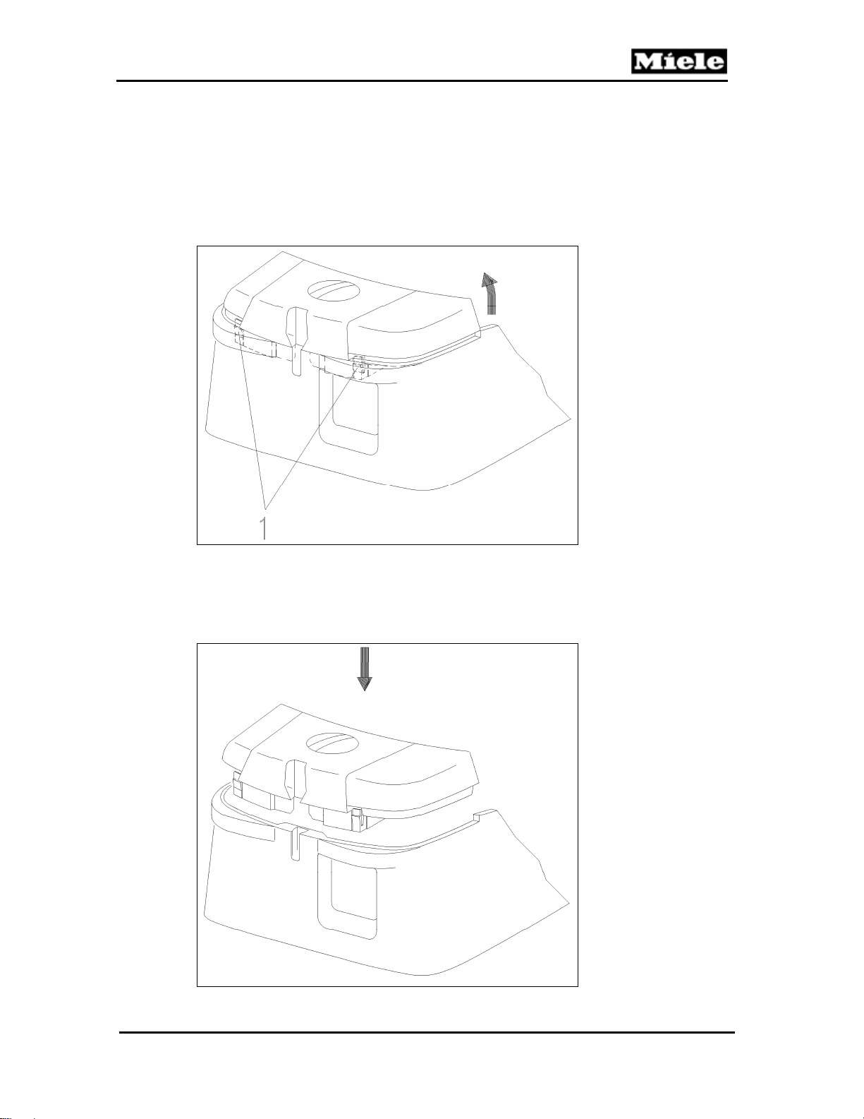
1. Install the hinges (Figure 020-6, Item 1) and hinge arms in the guides.
S 500 & S 600 Canister Vacuums
Figure 020-6: Casing Top Installation
2. Press the casing top downwards until it clips into place.
3. Install the filter.
4.4 Casing Top Replacement
Note:
The built-in socket (if applicable), accessory compartment lid, bag
change indicator, lid catch, torsion spring, hinges, slide shutter, holder,
slide sleeve and dust channel must be removed from the old casing top
and be installed in the new one.
1. Remove the accessory compartment lid. See Section 020-4.1.
2. Remove the accessories.
3. Remove the casing top. See Section 020-4.2.
4. Remove the slide sleeve and dust channel. See Section 020-4.7.
5. Remove the built-in socket, if applicable. See Section 020-4.14.
6. Install in reverse order on the new part. See Slide Sleeve and Dust
Channel Installation, Section 020-4.8, and Built-In Socket Installation,
Section 020-4.15.
30
Page 31
500 & S 600 Canister Vacuums
4.5 Cover Frame Removal
1. Remove the casing top. See Section 020-4.2.
2. Remove the cap. See Section 030-4.1.
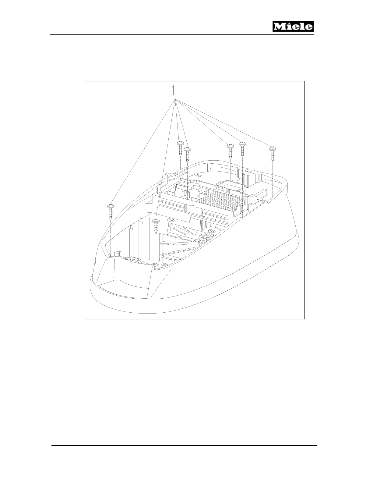
3. Remove the 7 screws from the cover frame; see Figure 020-7, Item 1.
Technical Information
Figure 020-7: Cover Frame Screws
4. Remove the cover frame.
4.6 Bag Change Indicator Removal
1. Remove the accessory compartment lid. See Section 020-4.1.
2. Remove the accessories.
3. Open the casing top.
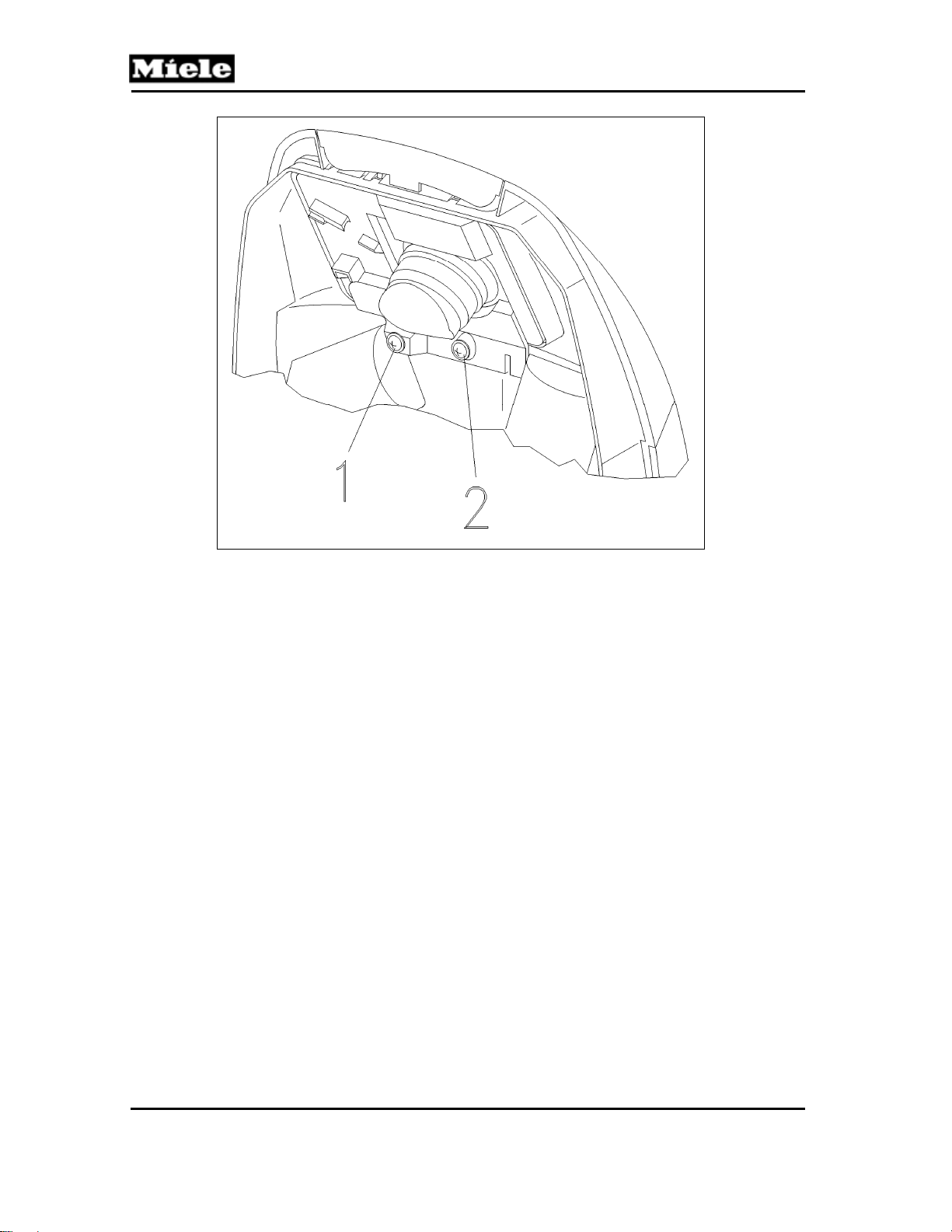
4. Remove the right-hand screw from the dust channel holder (Figure 020-8,
Item 2).
31
Page 32
Technical Information
S 500 & S 600 Canister Vacuums
Figure 020-8: Dust Channel Holder Screws
5. Remove the bag change indicator.
4.7 Slide Sleeve and Dust Channel Removal
1. Remove the accessory compartment lid. See Section 020-4.1.
2. Remove the accessories.
3. Remove the casing top. See Section 020-4.2.
4. Remove the hygienic slide shutter from the suction opening.
5. Remove the 2 screws from the dust channel holder (Figure 020-8, Items 1
and 2) and remove the holder.
6. Remove the bag change indicator.
7. Insert two fingers through the suction opening and press out the slide
sleeve and dust channel.
8. Remove the casing catch.
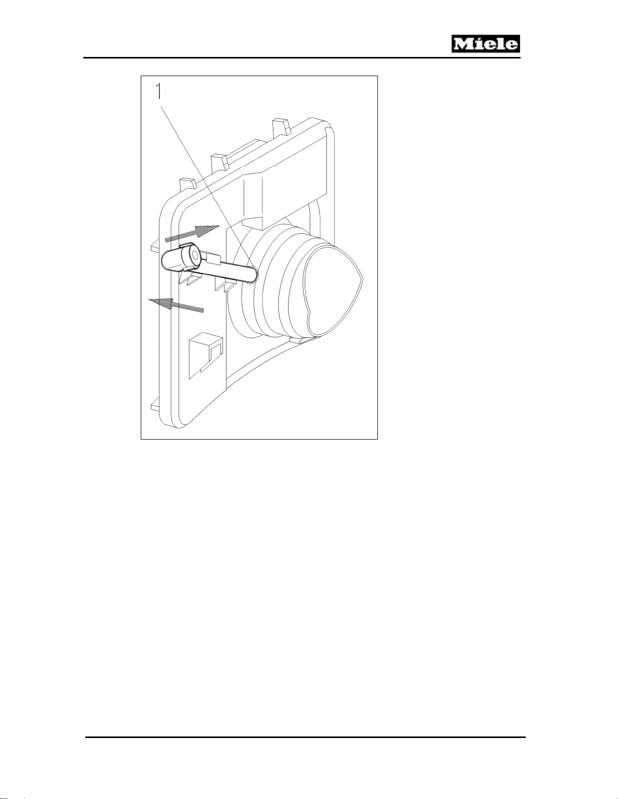
9. If applicable, lift the connection piece and remove it from the dust channel;
see Figure 020-9.
32
Page 33
500 & S 600 Canister Vacuums
Technical Information
Figure 020-9: Connection Piece Removal
10. Press the slide sleeve out of the dust channel.
4.8 Slide Sleeve and Dust Channel Installation
1. Install the casing top catch; see Section 020-4.12 or 020-4.13.
2. Install the built-in socket (if applicable). See Section 020-4.15.
3. Install the connection piece (if applicable). The connection piece must be
installed firmly in the slide sleeve. See Figure 020-9, Item 1.
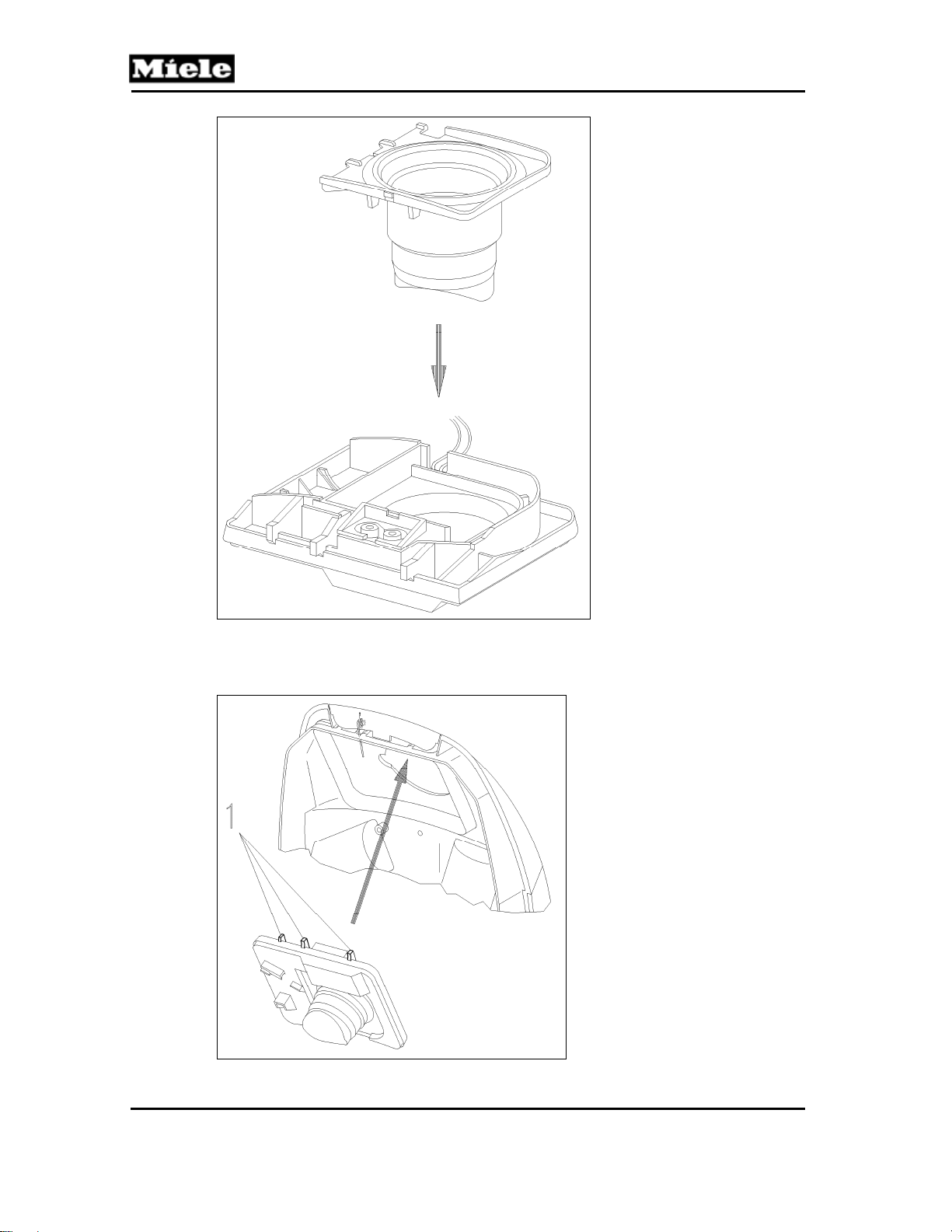
4. Pre-assemble the slide sleeve and dust channel; see Figure 020-10.
33
Page 34
Technical Information
S 500 & S 600 Canister Vacuums
Figure 020-10: Slide Sleeve and Dust Channel Pre-Assembly
5. Insert the dust channel tabs (Figure 020-11, Item 1) first; then press the
assembly into place while holding the casing catch in position.
Figure 020-11: Slide Sleeve and Dust Channel Installation
34
Page 35
500 & S 600 Canister Vacuums
6. Install the bag change indicator.
7. Screw the holder for the dust channel and bag change indicator back into
place.
8. Re-install the slide shutter as described under Slide Shutter
Replacement, Section 020-4.9.
4.9 Slide Shutter Replacement
1. Pull the slide shutter out of the suction opening.
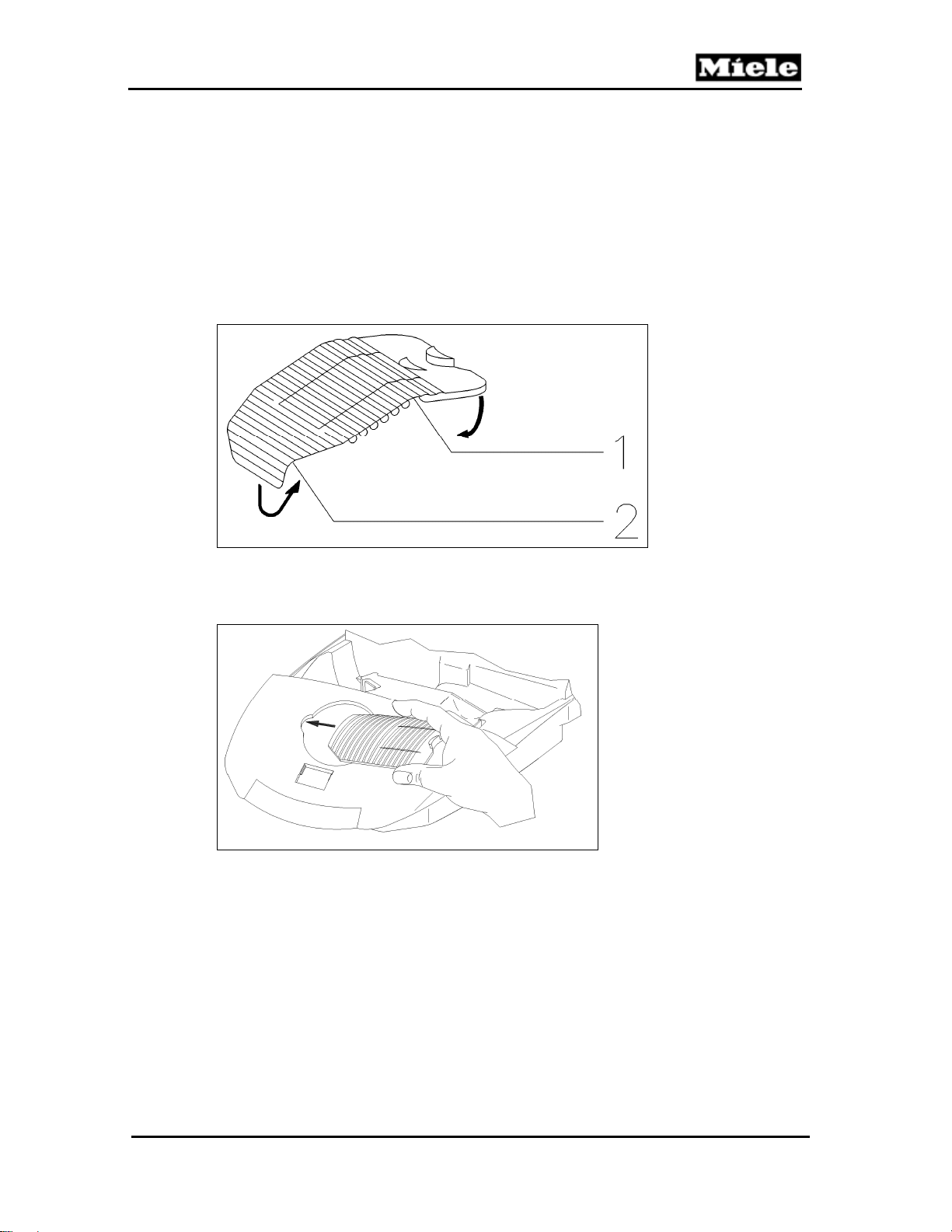
2. Bend the new slide shutter first by 180° (Figure 020-12, Item 1) and then
by 90° (Figure 020-12, Item 2), and roll it a little.
Technical Information
Figure 020-12: Bending the Slide Shutter
3. Press and curl the shutter together slightly parallel to the slots (closure tab
pointing to the right) and slide it into its guide; see Figure 020-13.
Figure 020-13: Installing the Slide Shutter
4.10 Casing Top Catch Removal (S 500 Models)
1. Remove the 2 screws from the dust channel holder (see Figure 020-8,
Items 1 and 2) and remove the holder.
2. Insert two fingers through the suction opening and press out the slide
sleeve and dust channel.
3. Remove the casing top catch.
4.11 Casing Top Catch Removal (S 600 Models)
1. Remove the casing top. See Section 020-4.2.
2. Unclip the catch using a screwdriver. See Figure 020-14.
35
Page 36

Technical Information
S 500 & S 600 Canister Vacuums
Figure 020-14: Releasing the Catch
4.12 Casing Top Catch Installation (S 500 Models)
1. Install the spring on its holder on the catch; see Figure 020-15.
2. Insert the spring through the slot and place the catch in position on the
casing top. See Figure 020-15.
Figure 020-15: Spring Position (S 500 Models)
3. For further assembly, see Slide Sleeve and Dust Channel Installation,
Section 020-4.8.
4.13 Casing Top Catch Installation (S 600 Models)
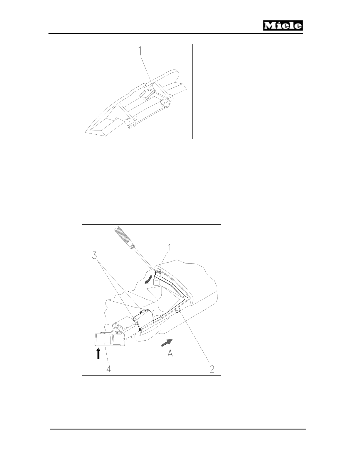
1. Install the spring on its holder on the catch; see Figure 020-16, Item 1.
2. Re-install the catch in the casing top.
36
Page 37
500 & S 600 Canister Vacuums
Technical Information
Figure 020-16: Spring Position (S 600 Models)
4.14 Built-In Socket Removal
1. Remove the accessory compartment lid. See Section 020-4.1.
2. Remove the accessories.
3. Remove the casing top. See Section 020-4.2.
4. Remove the slide sleeve and dust channel. See Section 020-4.7.
5. Use a screwdriver to release the cover strip locking tab; see Figure 020-17, Item 1.
6. Lift the cover strip to release the tab; see Figure 020-17, Item 2. Pull the
cover strip in the direction of arrow A to release it from its retainer; see
Figure 020-17, Item 3.
Figure 020-17: Cover Strip Removal
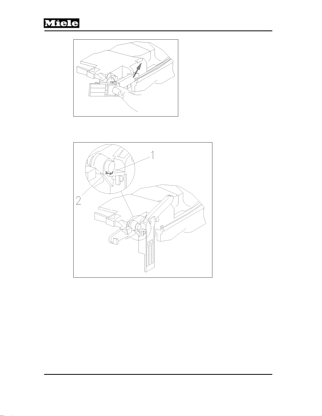
7. Press the cover strip out of its guide while holding the hinge (Figure 020-18)
in position.
37
Page 38
Technical Information
S 500 & S 600 Canister Vacuums
Figure 020-18: Removing the Cover Strip from Its Guide
8. Turn the hinge so that the locking tab (Figure 020-19, Item 1) lines up with
the hinge slot (Figure 020-19, Item 2). Remove the hinge.
Figure 020-19: Hinge Removal
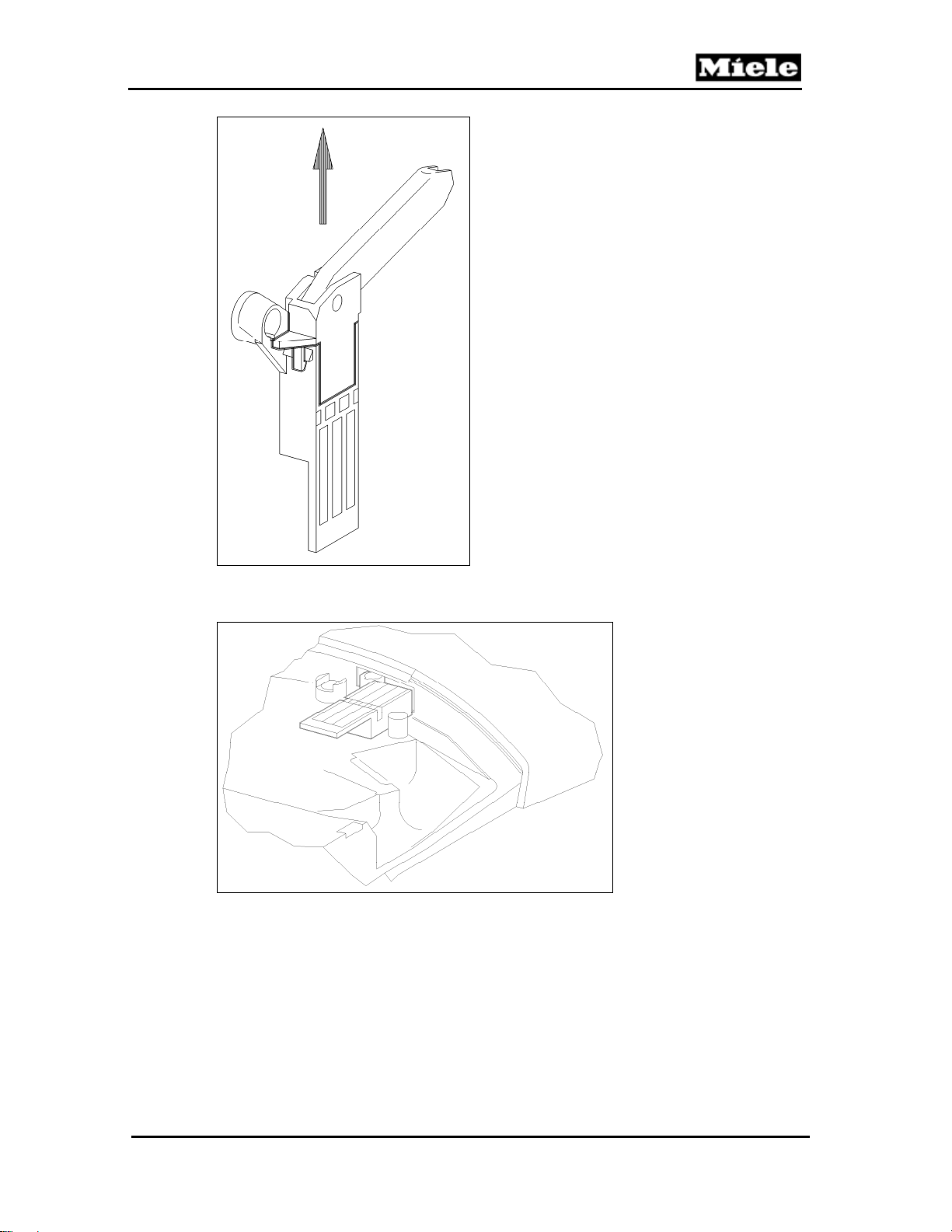
9. Remove the cord guide with cover from the hinge; see Figure 020-20.
38
Page 39
500 & S 600 Canister Vacuums
Technical Information
Figure 020-20: Cord Guide with Cover Removal
10. Remove both parts through the opening in the casing top; see Figure 020-21.
Figure 020-21: Hinge Removal through Casing Top Opening
39
Page 40
Technical Information
4.15 Built-In Socket Installation
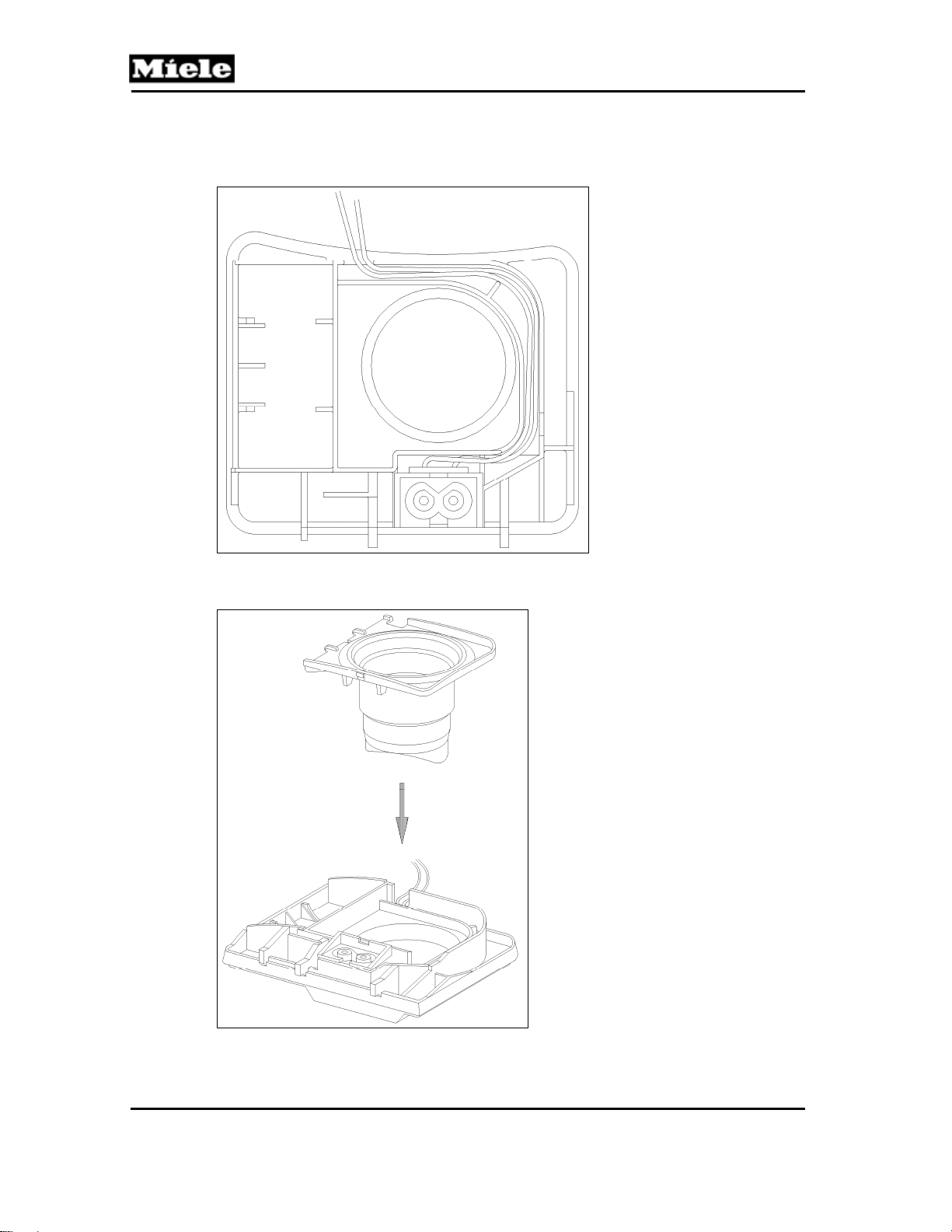
1. Install the built-in socket in the dust channel and lay the wires in the guide;
see Figure 020-22.
S 500 & S 600 Canister Vacuums
Figure 020-22: Built-In Socket Installation
2. Install the slide sleeve; see Figure 020-23. Ensure that the wires are not trapped.
Figure 020-23: Slide Sleeve Installation
3. Slide Sleeve and Dust Channel Installation, Section 020-4.8.
40
Page 41
500 & S 600 Canister Vacuums
4. Feed the hinge and cord guide with cover through the opening and
connect them together. The hinge can only be passed through the opening
in the position shown in Figure 020-21.
5. Install the hinge. Turn the hinge so that the locking tab (Figure 020-20,
Item 1) lines up with the hinge slot (Figure 020-20, Item 2).
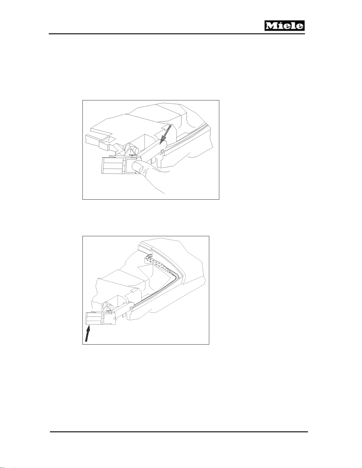
6. Turn the hinge upwards and install the cover on the cord guide. See arrow,
Figure 020-24.
Technical Information
Figure 020-24: Install the Cover on the Cord Guide
7. Hold the hinge upwards and lay the wires in the cord guide; see Figure 020-
25. Install the cover strip by clipping its tabs into position in reverse order
(Figure 020-17, Items 3, 2 and 1).
Figure 020-25: Laying the Wires in the Cord Guide
41
Page 42
Technical Information
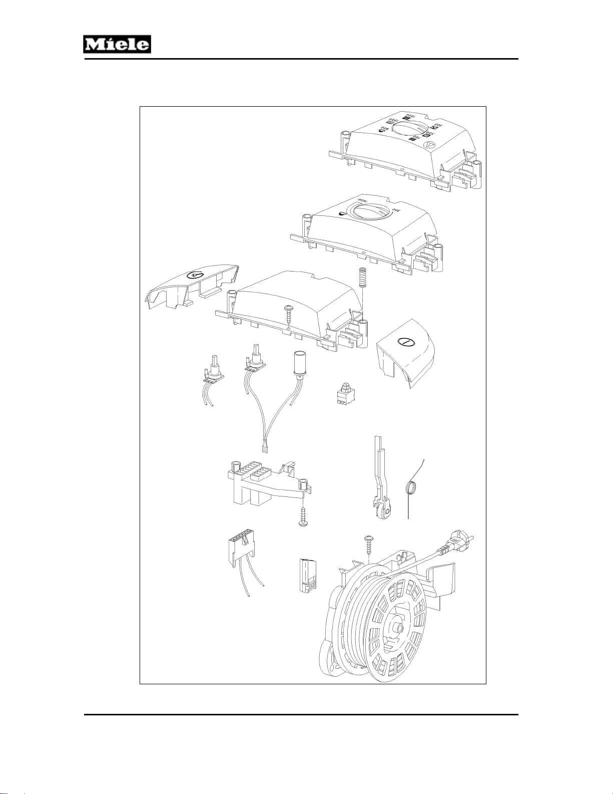
030 Operating Unit
S 500 & S 600 Canister Vacuums
S 51x/S 61x shown
42
Page 43

500 & S 600 Canister Vacuums
3 Fault Repair
3.1 Vacuum Cleaner Cannot Be Switched On
Cause:
On/off switch faulty.
Remedy:
1. Remove the cap; see Section 030-4.1.
2. Check the switch contacts for continuity.
3. If continuity does not exist, replace the on/off switch. See On/Off Switch
Removal, Section 030-4.5.
Cause:
Park System switch faulty.
Remedy:
Check the switch contacts for continuity. If continuity does not exist, replace the
Park System switch. See Park System Switch Removal, Section 030-4.11.
Cause:
Electronic in the cap is faulty.
Remedy:
See Cap Electronic Replacement, Section 030-4.12.
Technical Information
Cause:
1. Faulty cord reel.
2. Faulty cord.
Remedy:
1. Remove the cord reel; see Section 030-4.3.
2. Check for voltage on the back of the cord reel (between terminals L and
N). Voltage reading should be 120VAC +/- 10 volts.
3. If cord reel voltage is faulty (or nonexistent), then the cord reel is defective.
Replace it with a new one, following the instructions in Section 030-4.3.
4. If cord reel voltage is correct, then check voltage at the cord. Measure
between the black and white wires on the front of the cord reel (visible
through the “window”). Voltage reading should be 120VAC +/- 10 volts.
5. If cord voltage is faulty (or nonexistent), then the cord is defective. Replace
it with a new one, following the instructions in Section 030-4.4.
Cause:
Motor electronic is faulty.
Remedy:
Replace the motor electronic; see Section 040-4.4.
3.2 Vacuum Cleaner Shuts Itself Off or Overheating Indicator LED
Lights Up
Cause:
Floor attachment or suction hose blocked.
The motor has overheated and the thermostat has tripped.
Remedy:
Switch off the appliance.
Clean the floor attachment or suction hose.
43
Page 44
Technical Information
Cause:
Bag is full or fine dust has made it non-porous.
The motor has overheated and the thermostat has tripped.
Remedy:
Switch off the appliance.
Replace the bag. See Section 010-4.6.
Cause:
Filters are dirty.
The motor has overheated and the thermostat has tripped.
Remedy:
Switch off the appliance.
Replace the filters. See Sections 010-4.7 through 010-4.10.
Note:
After any of the above problems has been rectified, the vacuum cleaner must
be allowed to cool for approximately 30 minutes. It can then be used again.
Cause:
Motor electronic is faulty.
Remedy:
Replace the motor electronic; see Section 040-4.4.
3.3 Fuse Trips
S 500 & S 600 Canister Vacuums
Cause:
Increased starting current. The starting current can cause the fuse to trip.
According to the operating instructions a vacuum cleaner should be protected
by a 10-amp or 16-amp slow-blow fuse.
Remedy:
The vacuum cleaner should be switched on at a lower power setting. If this
does not remedy the fault, install a new electronic, mat. no. 05400250. This
electronic is equipped with an NTC sensor to limit the starting current.
Note:
Fuse H10 can still trip when the vacuum cleaner is switched on.
3.4 Cord Is Not Fully Rewound
Causes:
1. Cord reel rewind spring is too weak.
2. Cord reel rewind spring has worked free.
3. Cord not properly guided when rewinding.
Remedy:
Install a new cord reel, mat. no. 05093721. See Section 030-4.3.
3.5 Autoreverse Slide Blocked
Cause:
Gear rack (toothed rack) has come loose.
Remedy:
Install the autoreverse foot switch, mat. no. 05363730 (S 544, S 548, S 558),
44
Page 45

500 & S 600 Canister Vacuums
or mat. no. 05368030 (S 624, S 658).
3.6 Electronics Troubleshooting
1. For S 558 and S 658 (Silver Moon and Blue Moon): Do handle lights turn
on and step through? If yes, go to Step 2. If not, go to Step 8.
2. Unplug the vacuum. Disconnect the hose and remove the casing top
(Section 020-4.2) and the cap (Section 030-4.1).
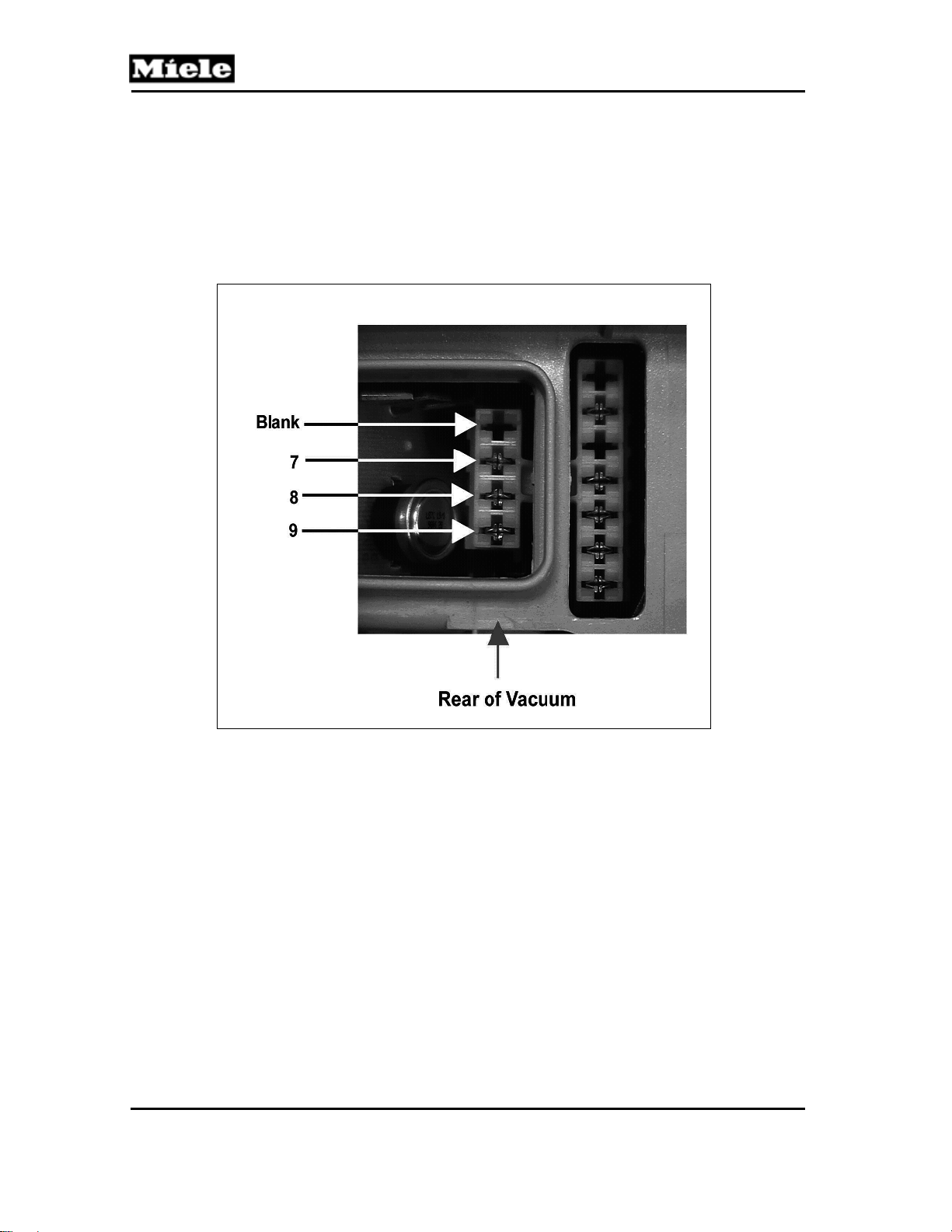
3. Check resistance across pins 7 and 8 at the motor connector (refer to
Figure 030-1). Resistance should be between 52 and 70 ohms.
4. If motor connector resistance is not between 52 and 70 ohms, then the
motor electronic is faulty. Replace it, following the instructions in Section
040-4.4.
5. If motor connector resistance is between 52 and 70 ohms, then test
continuity between pins 7 and 9 at the motor connector. If there is
continuity between these pins, then the motor electronic is faulty. Replace
it, following the instructions in Section 040-4.4.
6. If there is no continuity between pins 7 and 9 at the motor connector, then
test continuity between pins 8 and 9 at the motor connector. If there is
continuity between these pins, then the motor electronic is faulty. Replace
it, following the instructions in Section 040-4.4.
7. If there is no continuity between pins 8 and 9 at the motor connector, then
remove the cover frame (Section 020-4.5) and test for continuity across
the motor itself. If there is continuity across the motor, then the cap
electronic is faulty. Replace it, following the instructions in Section 030-
4.12. If there is no continuity across the motor, then the motor is faulty;
replace it, following the instructions in Section 040-4.1.
8. For S 558 and S 658 (Silver Moon and Blue Moon): If handle lights do not
turn on/step through, disconnect the hose from the vacuum and check for
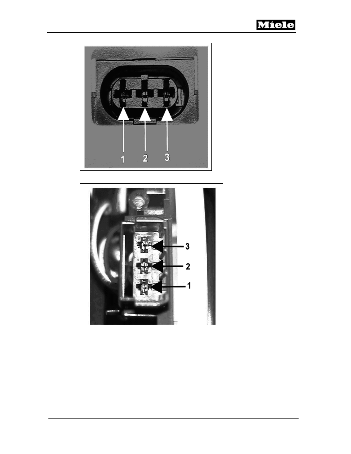
8.4 volts across pins 2 and 3 at the hose connection (see Figure 030-2).
9. If there is 8.4 volts across pins 2 and 3 at the hose connection, then check
for 0.4 volts across pins 1 and 2 and pins 1 and 3 at the hose connection.
If there is 0.4 volts across pins 1 and 2 and pins 1 and 3, then the hose
electrical connection is faulty. Replace the hose, following the instructions
in Section 055-4.1.
10. If there is not 8.4 volts across pins 2 and 3 at the hose connection, remove
the casing top (Section 020-4.2) and check for 8.4 volts across pins 2 and
3 at the hinge connection (see Figure 030-3).
11. If there is 8.4 volts across pins 2 and 3 at the hinge connection, then check
for 0.4 volts across pins 1 and 2 and pins 1 and 3 at the hinge connection.
If there is 0.4 volts across pins 1 and 2 and pins 1 and 3, then the flush
socket outlet has a broken connection. Replace it, following the
instructions in Sections 020-4.14 and 020-4.15.
12. If there is not 8.4 volts across pins 2 and 3 at the hinge connection, then
remove the cap (Section 030-4.1), cover frame (Section 020-4.5) and cap
electronic (Section 030-4.12). Place the cap electronic on the connections
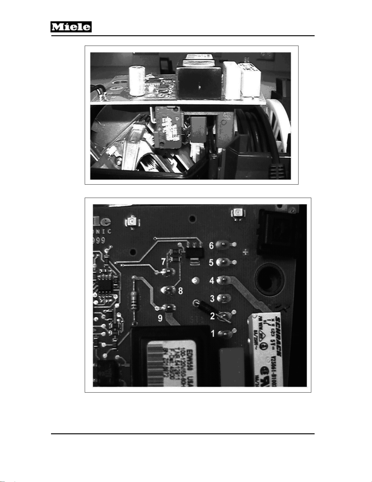
at the vacuum (see Figure 030-4).
13. Check for 8.4 volts across pins 2 and 3 at the cap electronic (see Figure
030-5). If there is not 8.4 volts between pins 2 and 3, then the cap
electronic is faulty. Replace it, following the instructions in Section 030-
4.12.
Technical Information
45
Page 46
Technical Information
14. If there is 8.4 volts between pins 2 and 3 at the cap electronic, then check
for 0.4 volts between pins 1 and 2 and 1 and 3 at the cap electronic. If
there is not 0.4 volts between pins 1 and 2 and pins 1 and 3 at the cap
electronic, then the cap electronic is faulty. Replace it, following the
instructions in Section 030-4.12.
15. If there is 0.4 volts between pins 1 and 2 and pins 1 and 3 at the upper
electronic, then the connecting cable (power cord) has a broken
connection. Replace it, following the instructions in Section 030-4.4.
S 500 & S 600 Canister Vacuums
Figure 030-1: Electronic Connections
46
Page 47
500 & S 600 Canister Vacuums
Technical Information
Figure 030-2: Direct-Connect Hose Connection
Figure 030-3: Direct-Connect Hinge Connections
47
Page 48
Technical Information
S 500 & S 600 Canister Vacuums
Figure 030-4: Electronic (Side View)
Figure 030-5: Electronic (Top View)
48
Page 49
500 & S 600 Canister Vacuums
4 Service
4.1 Cap Removal
1. Remove the casing top; see Section 020-4.2.
2. Remove the cap retaining screw.
3. Pull the cap upwards at an angle. The locking tabs (Figure 030-6, Item 1)
will then be released.
Technical Information
Figure 030-6: Cap Removal
4.2 Cap Installation
1. Locate the cap on its plug contacts, press it down straight and screw tight;
see Figure 030-7.
Figure 030-7: Cap Installation
49
Page 50
Technical Information
4.3 Cord Reel Removal
Note:
The cord reel may only be replaced as a complete assembly.
1. Remove the casing top; see Section 020-4.2.
2. Remove the cap; see Section 030-4.1.
3. Remove the cover frame; see Section 020-4.5.
4. Remove the cord reel retaining screw.
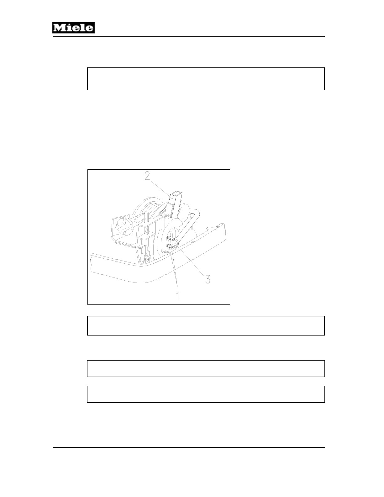
5. Disconnect the 2 plug contacts; see Figure 030-8, Item 1.
6. Disconnect the hose (Figure 030-8, Item 3) from the cord reel.
7. Press out the hinge socket (Figure 030-8, Item 2) from its anchor on the
cord reel.
8. Remove the cord reel.
S 500 & S 600 Canister Vacuums
Figure 030-8: Cord Reel Removal
Note:
Before installing the casing top, insert the power cord through its opening.
4.4 Cord Removal
Note:
Use only a genuine Miele cord for the correct vacuum model number.
Note:
Never replace the cord end.
1. Remove the cord reel. See Section 030-4.3.
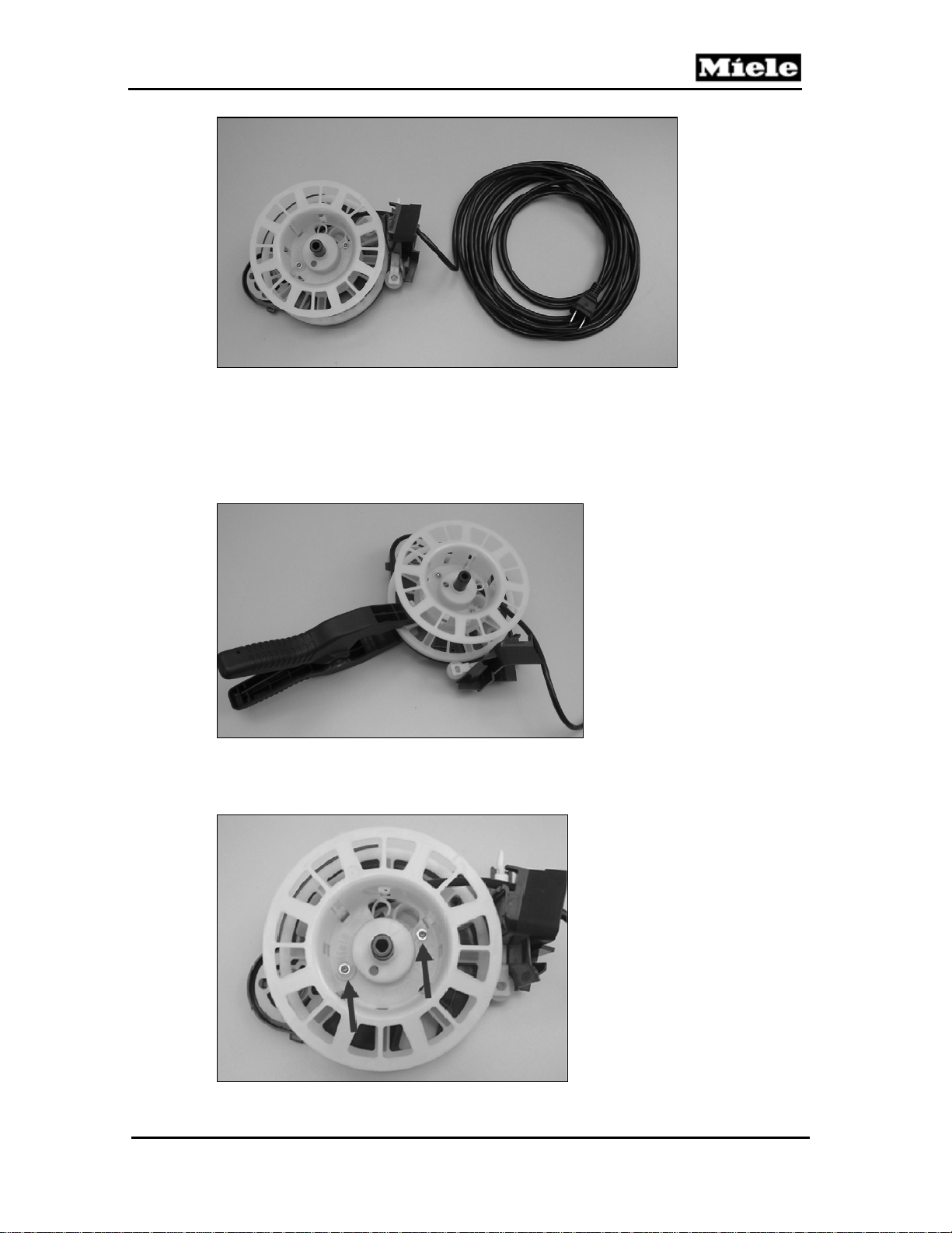
2. Unwind the cord completely. See Figure 030-9.
50
Page 51
500 & S 600 Canister Vacuums
Technical Information
Figure 030-9: Cord Reel, Unwound
3. Clamp the cord reel to the body of the cord reel assembly to immobilize it.
See Figure 030-10. Failure to clamp the cord reel can allow it to rotate,
changing the spring tension and affecting operation. The reel can also
separate from the body, releasing the tension spring. Always clamp the
reel to the body before performing any cord repair.
Figure 030-10: Cord Reel Clamped to Reel Assembly Body
4. Once the clamp is in place, remove the 2 T10 screws from the cord reel.
See Figure 030-11.
Figure 030-11: Screws Securing Cord Reel
51
Page 52
Technical Information
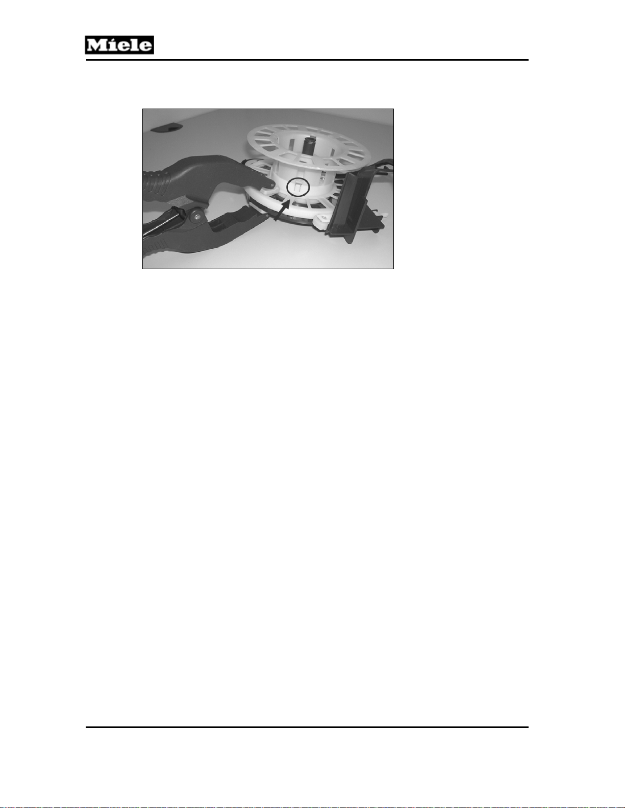
5. Release the tabs holding the two halves of the cord reel together. See
Figure 030-12. The top of the reel will lift straight up.
S 500 & S 600 Canister Vacuums
Figure 030-12: Cord Reel Tabs
6. Remove the cord from the cord reel.
7. Install the new cord.
8. Reassemble the reel halves. Do not remove the clamp until the cord reel
halves are fully assembled.
9. When the reel has been reassembled, remove the clamp and retract the
cord slowly, leaving a 6” tail. Once the cord reel is installed in the vacuum
it is important to do an operational check and ensure that the cord extends
and retracts correctly.
4.5 On/Off Switch Removal
1. Remove the casing top; see Section 020-4.2.
2. Remove the cap; see Section 030-4.1.
3. Remove the on/off switch from its holder.
4. Disconnect the plug contacts.
4.6 Foot Switch Removal
1. Remove the casing top; see Section 020-4.2.
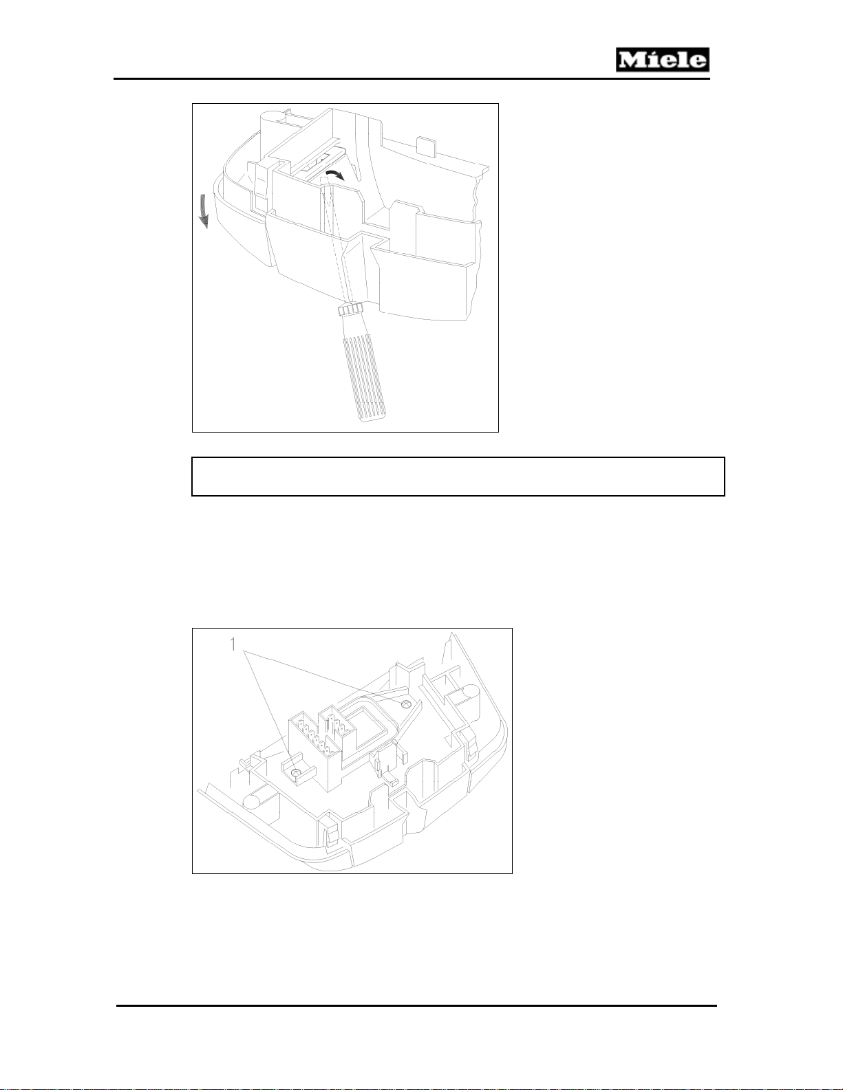
2. Remove the cap; see Section 030-4.1.
3. Turn the cap over. Press the foot switch and use a small screwdriver to
lever it out at the left and right. See Figure 030-13.
52
Page 53
500 & S 600 Canister Vacuums
Technical Information
Figure 030-13: Levering Out the Foot Switch
Note:
Do not lever with the screwdriver in the middle as the retainer can then break.
4.7 Plug Housing Removal
1. Remove the casing top; see Section 020-4.2.
2. Remove the cap; see Section 030-4.1.
3. Remove the on/off switch from its holder.
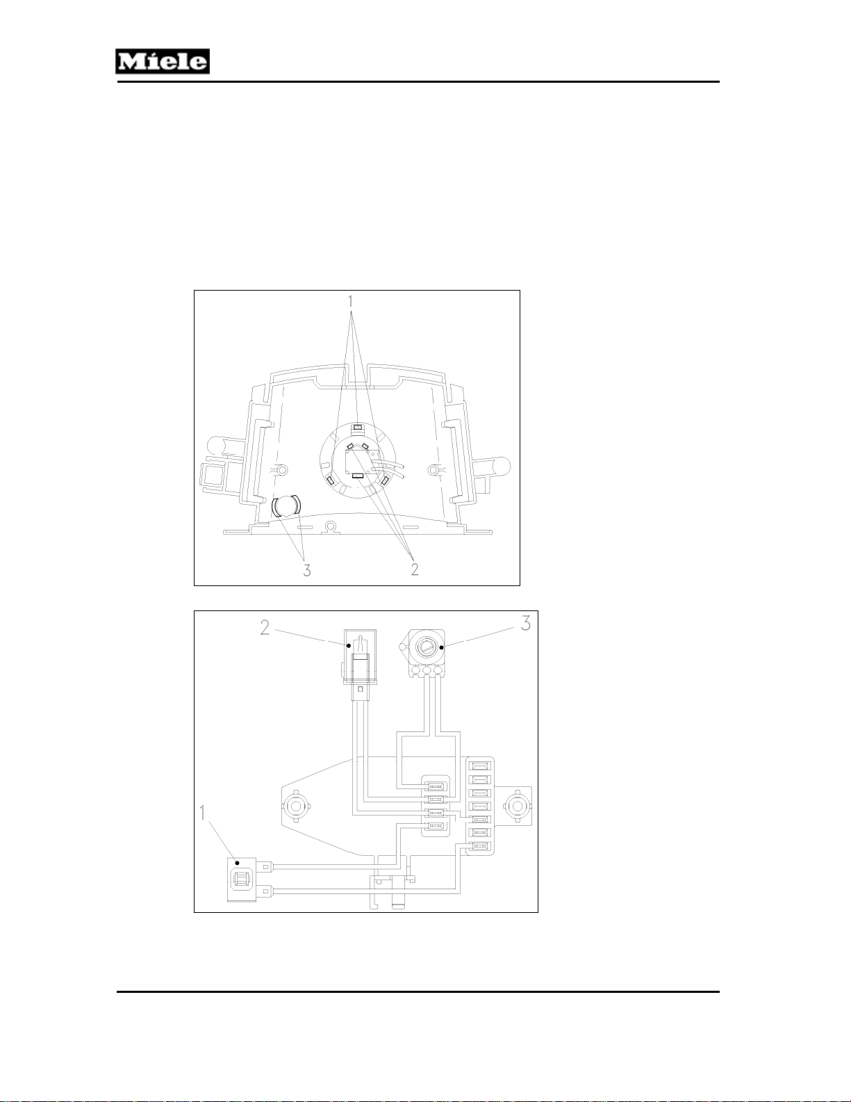
4. Remove the plug housing screws; see Figure 030-14, Item 1. Remove the
plug housing.
Figure 030-14: Plug Housing Removal
53
Page 54
S 500 & S 600 Canister Vacuums
Technical Information
4.8 Potentiometer (and Indicator Light) Removal (S 51x)
1. Remove the casing top; see Section 020-4.2.
2. Remove the cap; see Section 030-4.1.
3. Remove the plug housing; see Section 030-4.7.
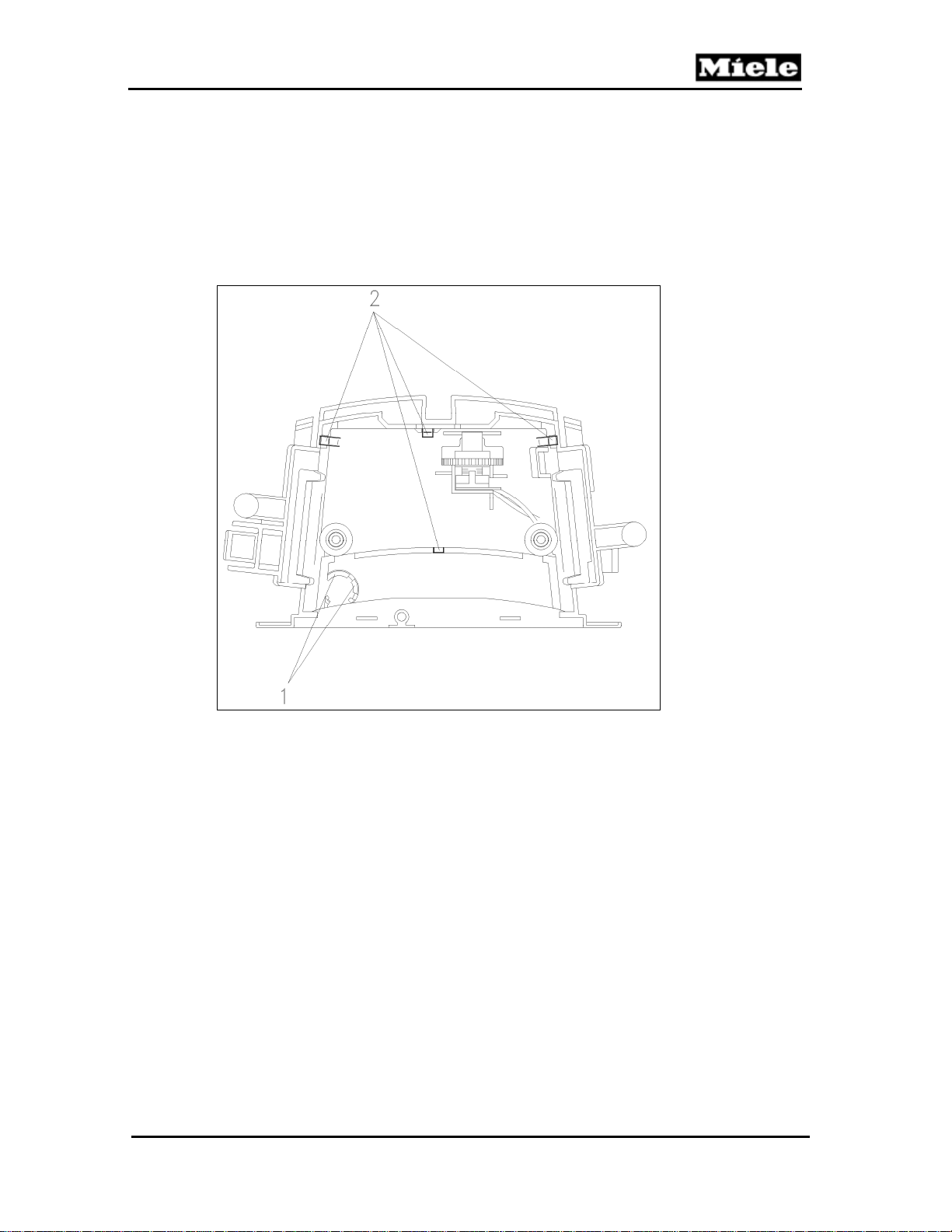
4. Use a screwdriver to release the 3 switch knob locking tabs; see Figure 030-
15, Item 1. Remove the switch knob.
5. Use a screwdriver to release the 3 potentiometer locking tabs; see Figure
030-15, Item 2. Remove the potentiometer.
6. If applicable, remove the indicator light from its holder. See Figure 030-15,
Item 3.
Figure 030-15: Potentiometer & Indicator Light Removal (S 51x)
1 Switch
2 Indicator light (if applicable)
3 Potentiometer
Figure 030-16: Plug Housing (S 51x)
54
Page 55
500 & S 600 Canister Vacuums
Technical Information
4.9 Potentiometer and Indicator Light Removal (S 52x, S 62x)
1. Remove the casing top; see Section 020-4.2.
2. Remove the cap; see Section 030-4.1.
3. Remove the plug housing; see Section 030-4.7.
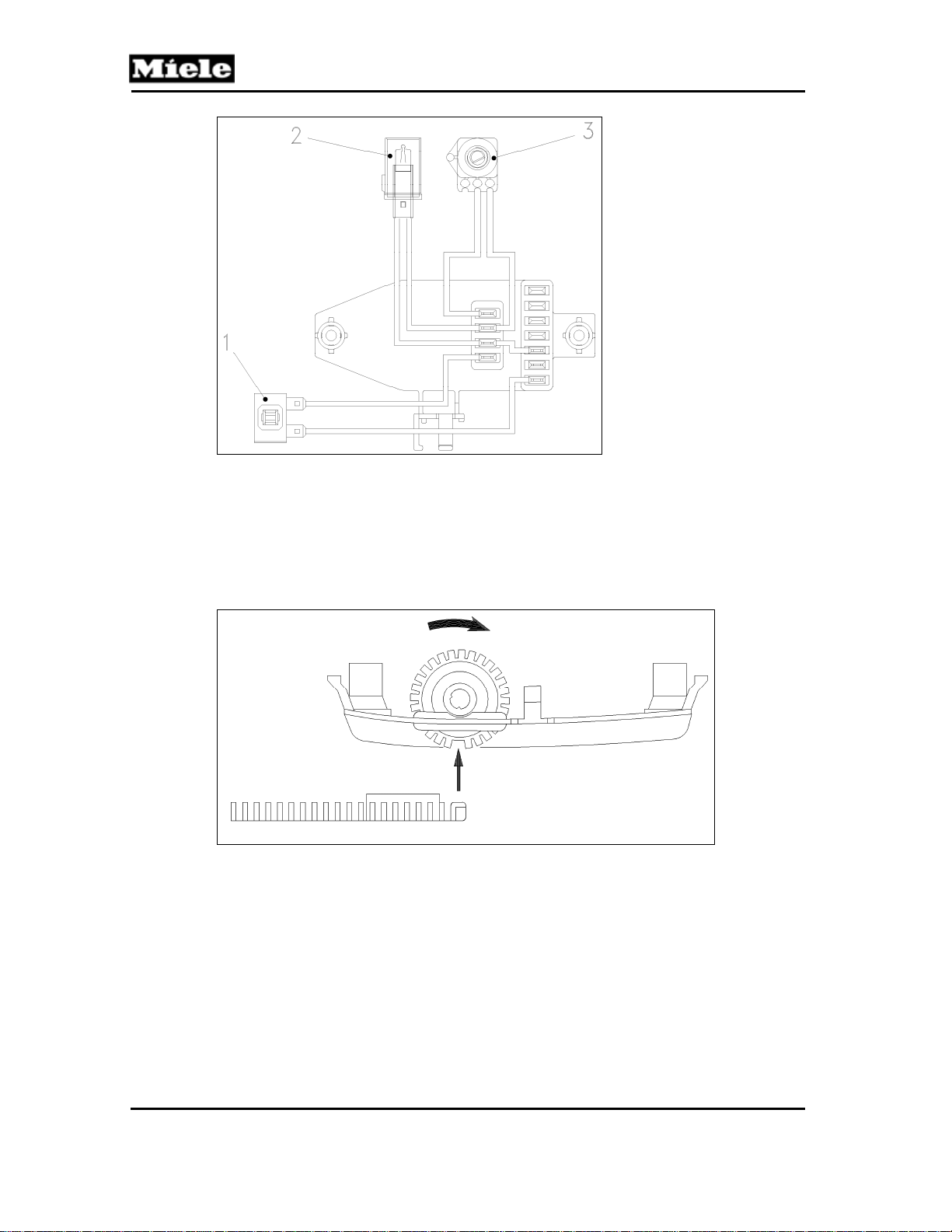
4. Use a screwdriver to release the indicator light locking tabs. See Figure 030-
17, Item 1. Remove the indicator light.
5. Use a screwdriver to release the 4 bracket locking tabs. See Figure 030-
17, Item 2. Remove the bracket.
Figure 030-17: Indicator Light and Bracket (S 52x, S 62x)
6. Slide the cog wheel off the potentiometer.
7. Remove the potentiometer and cog wheel.
8. Replace the potentiometer and indicator light.
55
Page 56
Technical Information
S 500 & S 600 Canister Vacuums
1 Switch
2 Indicator light (if applicable)
3 Potentiometer
Figure 030-18: Plug Housing (S 52x, S 62x)
9. Slide the cog wheel loosely onto the potentiometer.
10. Locate both in the bracket, then slide the cog wheel firmly onto the
potentiometer.
11. Push the slide to the maximum setting and hold it there.
12. Turn the cog wheel to its end stop. See Figure 030-19. Hold it in position
and install the bracket.
Figure 030-19: Position of Gear Rack and Cog Wheel (S 52x, S 62x)
4.10 Gear Rack Removal and Installation (S 52x, S 62x)
1. Remove the plug housing. See Section 030-4.7.
2. Use a screwdriver to release the indicator light locking tabs. See Figure
030-17, Item 1. Remove the indicator light.
3. Use a screwdriver to release the 4 bracket locking tabs. See Figure 030-
17, Item 2. Remove the bracket.
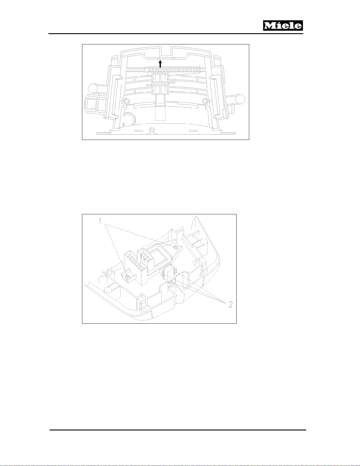
4. Push the slide to a middle setting. Slide off the gear rack; see Figure 030-20.
56
Page 57
500 & S 600 Canister Vacuums
Technical Information
Figure 030-20: Gear Rack Removal (S 52x, S 62x)
5. When re-installing, push the slide to the maximum setting and hold it there.
6. Turn the cog wheel to its end stop. See Figure 030-19. Hold it in position
and install the bracket.
4.11 Park System Switch Removal
1. Remove the plug housing. See Section 030-4.7.
2. Disconnect the switch plug connections.
3. Use a screwdriver to release the switch locking tabs. See Figure 030-21, Item 2.
Figure 030-21: Park System Switch Removal
4.12 Cap Electronic Replacement
1. Remove the plug housing. See Section 030-4.7.
2. Disconnect the on/off switch plug connections from the old electronic.
3. Connect the on/off switch plug connections to the new electronic.
57
Page 58
Technical Information
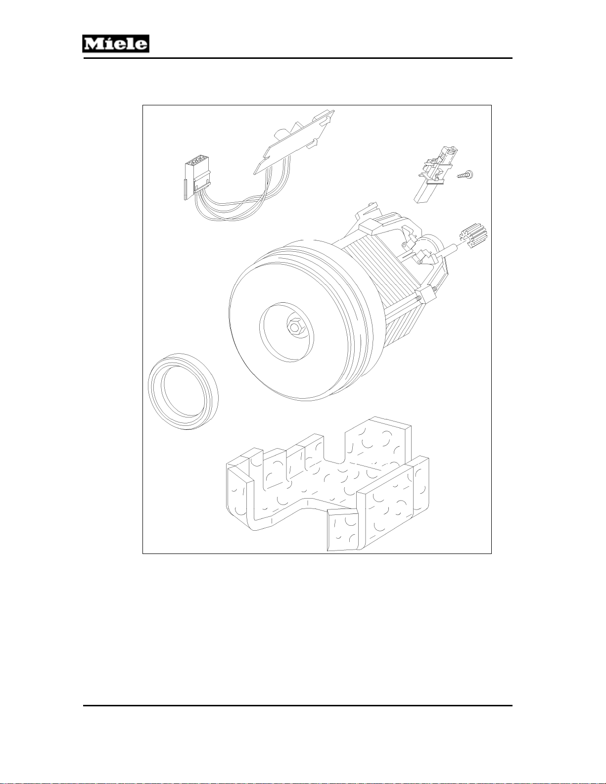
040 Motor
S 500 & S 600 Canister Vacuums
58
Page 59
500 & S 600 Canister Vacuums
4 Service
4.1 Motor Removal
1. Remove the casing top; see Section 020-4.2.
2. Remove the cap; see Section 030-4.1.
3. Remove the cover frame; see Section 020-4.5.
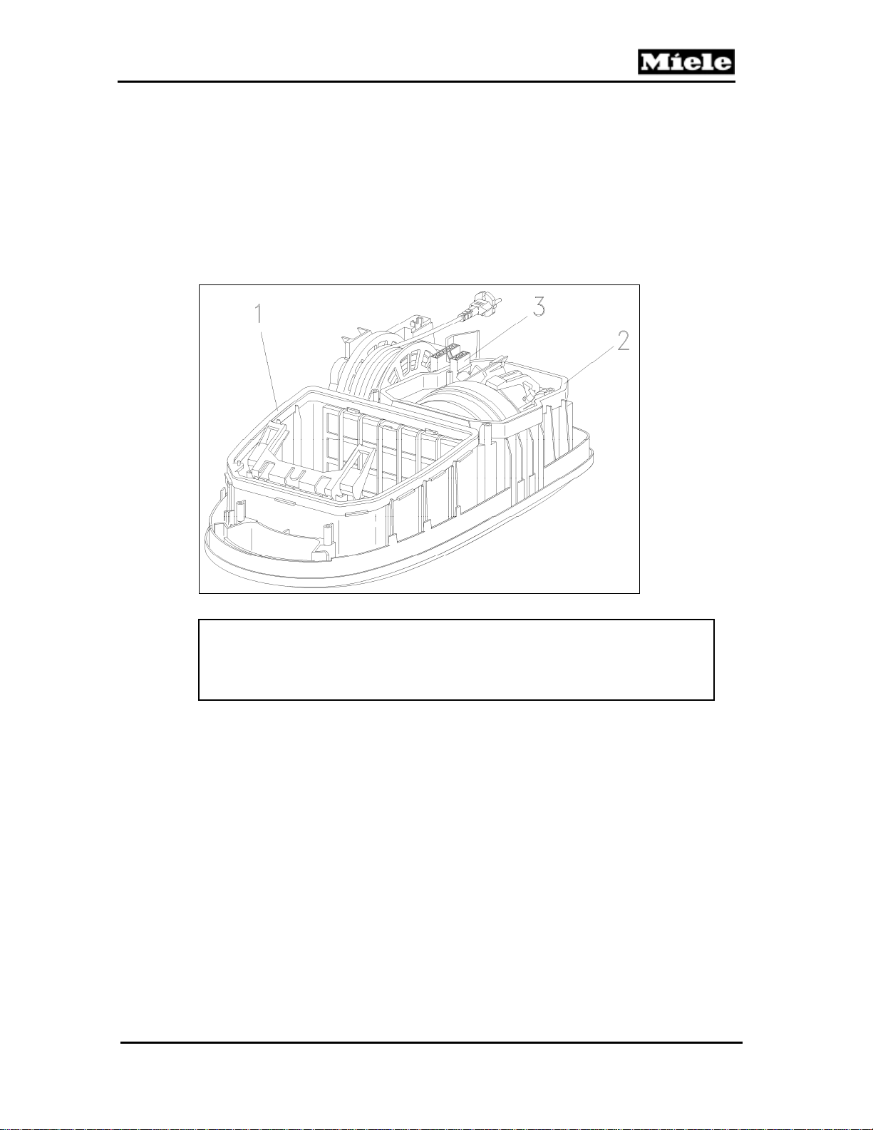
4. Remove the plug housing from its holder. See Figure 040-1, Item 3.
5. Remove the seal. See Figure 040-1, Item 2.
6. Remove the motor.
Technical Information
Figure 040-1: Motor Removal
Note:
Before the motor is installed, place the caps on the rubber cushions and
install the bearing ring. When installing the motor, ensure that the rubber
cushions are correctly seated in their holders.
4.2 Damping Plate Removal
1. Remove the motor; see Section 040-4.1.
2. Replace the damping plate.
4.3 Carbon Brush Removal
1. Remove the motor; see Section 040-4.1.
2. Remove the rubber cushions from the motor.
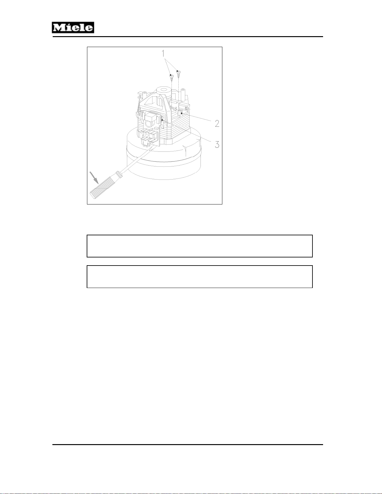
3. Remove the carbon brush holder retaining screws. See Figure 040-2, Item
1. Remove the carbon brushes with their holders.
59
Page 60
Technical Information
S 500 & S 600 Canister Vacuums
Figure 040-2: Carbon Brushes and Electronic
4. When installing, ensure that the plug contact (Figure 040-2, Item 2)
engages correctly.
Note:
Always replace both carbon brushes.
Warning!
Check the commutator for cord lines and burn marks.
4.4 Motor Electronic Replacement
1. Remove the motor. See Section 040-4.1.
2. Lever the electronic from the motor with a screwdriver; see Figure 040-2.
3. When installing, ensure that the plug contacts (Figure 040-2, Item 3)
engage correctly.
60
Page 61
500 & S 600 Canister Vacuums
050 Suction Hose
Technical Information
61
Page 62
Technical Information
3 Fault Repair
3.1 Suction Pow er Is Too Low
Cause:
Bag jammed between the casing top and the cover frame.
Remedy:
Replace the bag. See Section 010-4.6.
Note:
Do not open out the bag. Install it as it is when removed from its packaging.
Cause:
Floor attachment or suction hose blocked.
Remedy:
Clean the floor attachment or suction hose.
Cause:
Filter clogged.
Remedy:
Replace all filters. See Sections 010-4.7 through 010-4.10.
S 500 & S 600 Canister Vacuums
Cause:
Seal or sealing ring not seated correctly.
Remedy:
Check for correct seating. Reseat elbow or replace locking tabs as necessary.
3.2 Elbow Not Seated Correctl y in the Suction Opening
Cause:
The hygienic slide shutter slides in front of the suction opening.
Remedy:
Reseat elbow or replace locking tabs as necessary. Replace the slide shutter.
See Section 020-4.9.
3.3 Elbow Blocked
Cause:
The hygienic slide shutter slides in front of the suction opening.
Remedy:
Replace the slide shutter. See Section 020-4.9.
62
Page 63
500 & S 600 Canister Vacuums
055 Electro Suction Hose
(S 558, S 658)
Technical Information
63
Page 64
Technical Information
3 Fault Repair
3.1 Suction Pow er Is Too Low
Cause:
Bag jammed between the casing top and the cover frame.
Remedy:
Replace the bag. See Section 010-4.6.
Note:
Do not open out the bag. Install it as it is when removed from its packaging.
Cause:
Floor attachment or suction hose blocked.
Remedy:
Clean the floor attachment or suction hose.
Cause:
Filter clogged.
Remedy:
Replace all filters. See Sections 010-4.7 through 010-4.10.
S 500 & S 600 Canister Vacuums
Cause:
Seal or sealing ring not seated correctly.
Remedy:
Check for correct seating.
3.2 Elbow Not Seated Correctl y in the Suction Opening
Cause:
The hygienic slide shutter slides in front of the suction opening.
Remedy:
Replace the slide shutter. See Section 020-4.9.
3.3 Elbow Blocked
Cause:
The hygienic slide shutter slides in front of the suction opening.
Remedy:
Replace the slide shutter. See Section 020-4.9.
3.4 Appliance Alw ays Operates at Full Power
Cause:
Electronic in handle is defective.
Remedy:
Replace the suction hose with electronic; see Section 055-4.1.
Cause:
Poor contact between slip ring and electronic.
Remedy:
Replace the suction hose with electronic; see Section 055-4.1.
64
Page 65

500 & S 600 Canister Vacuums
3.5 Appliance Cannot Be Switched On
Cause:
Electronic in handle is defective.
Remedy:
Replace the suction hose with electronic; see Section 055-4.1.
Cause:
Poor contact between slip ring and electronic.
Remedy:
Replace the suction hose with electronic; see Section 055-4.1.
3.6 Power Level Cannot Be Adjusted
Cause:
Electronic in handle is defective.
Remedy:
Replace the suction hose with electronic; see Section 055-4.1.
Cause:
Poor contact between slip ring and electronic.
Remedy:
Replace the suction hose with electronic; see Section 055-4.1.
3.7 Electrobrush Cannot Be Selected
Technical Information
Cause:
Electronic in handle is defective.
Remedy:
Replace the suction hose with electronic; see Section 055-4.1.
Cause:
Poor contact between slip ring and electronic.
Remedy:
Replace the suction hose with electronic; see Section 055-4.1.
4 Service
4.1 Replacing the Suction Hose with Electronic
Danger!
For safety reasons the handle should not be dismantled as locking tabs
can become damaged. Safe and correct reassembly can then not be
ensured. To increase electrical safety, the hose connection at the handle
has been strengthened with a ring. Handles strengthened in this way
cannot be dismantled.
Only replace the suction hose as a complete assembly.
65
 Loading...