

Page 1
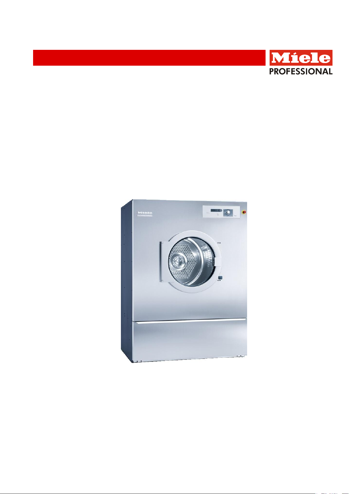
Installation plan
Tumble dryers
Installatieschema
Droogautomaat
PT 8503 G
PT 8505 G
PT 8507 G
nl - NL
en - GB
02.11 Mat. NR. 07 803 880 / 02
Page 2

2
Lees beslist de gebruiks- en montagehandleiding voordat u uw
apparaat plaatst, installeert en in gebruik neemt.
Dat is veiliger voor uzelf en u voorkomt schade aan uw apparaat.
Technische wijzigingen voorbehouden
It is essential to read the operating and installation instructions before
installing, commissioning or using the machine.
This avoids the risk of accidents or damage.
All rights reserved
Mat. NR. 07 803 880 / 02
Page 3
Page 4
Page 5
Page 6
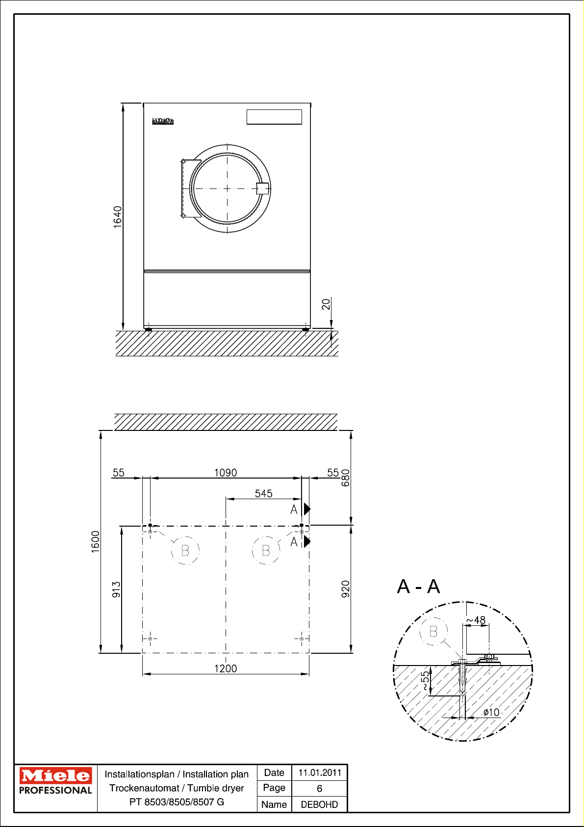
Page 7
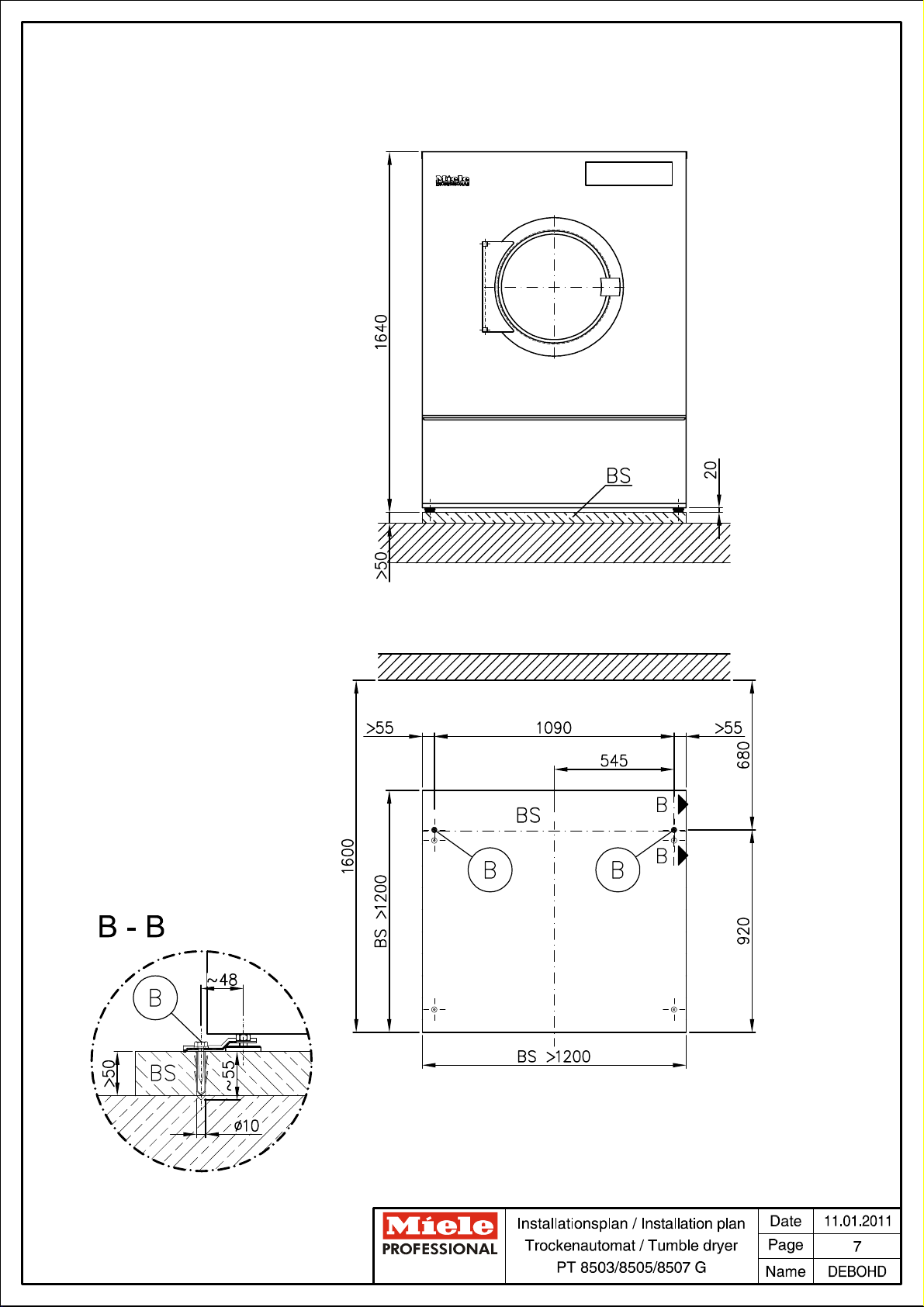
Page 8
Technical datasheet
Tumble dryer:
Heating:
PT 8503/8505/8507
Gas (G)
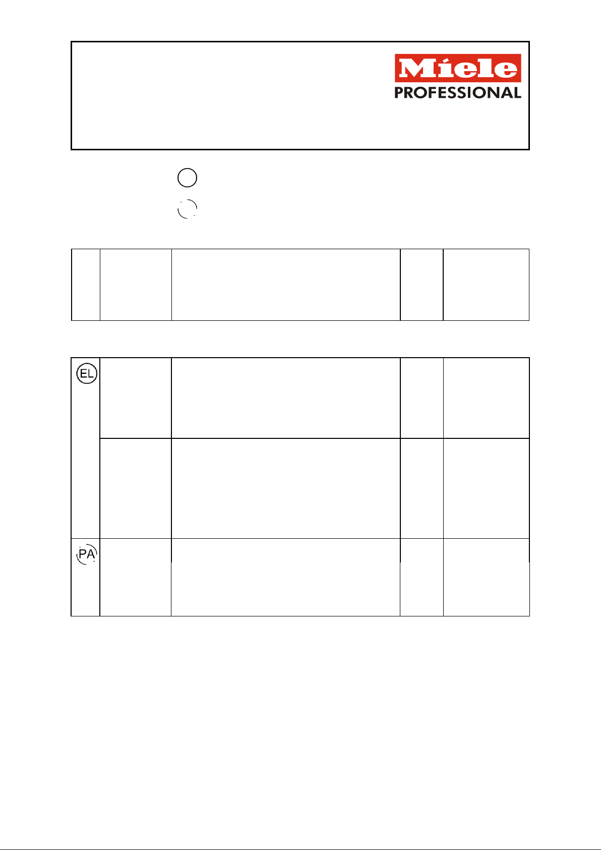
Legend:
Abbreviations in bold type:
Connection required
en - GB
Abbreviations in circle with dashes:
Connection optional or required depending on model version
BS
Concrete plinth
Quality and density of concrete must comply with load.
Concrete plinth must be firmly secured to floor!
Recommended height
mm
100
Minimum height
mm
50
Width min.
mm
1200
Width min.
mm
1100
Electrical
connection
1. Standard voltage (as supplied)
V 3N AC 380 - 415
Frequency
Hz
50
Rated load
kW
1.3
Fuse rating
A 3 × 10
Connection cable, min. cross-section
mm²
5 × 1.5
Cable screw connector
M 25
Connection cable (to be ordered separately)
Electrical connection must comply with national regulations.
Connection using multi-pole wall socket in compliance with
IEC/EN 60309 and IEC/EN 60947 is recommended in order to
simplify electrical tests.
If machines are hard-wired, a multi-pole mains switch must be
provided on site.
A wall socket or mains isolator must be accessible after
installation.
Equipotential
bonding
Connection with male thread
mm
10 × 35
with washers and nut.
M
10
Accessories to be ordered separately
If necessary, equipotential bonding with good galvanic
contact must be provided in accordance with all appropriate
national and local regulations.
Optional extras:
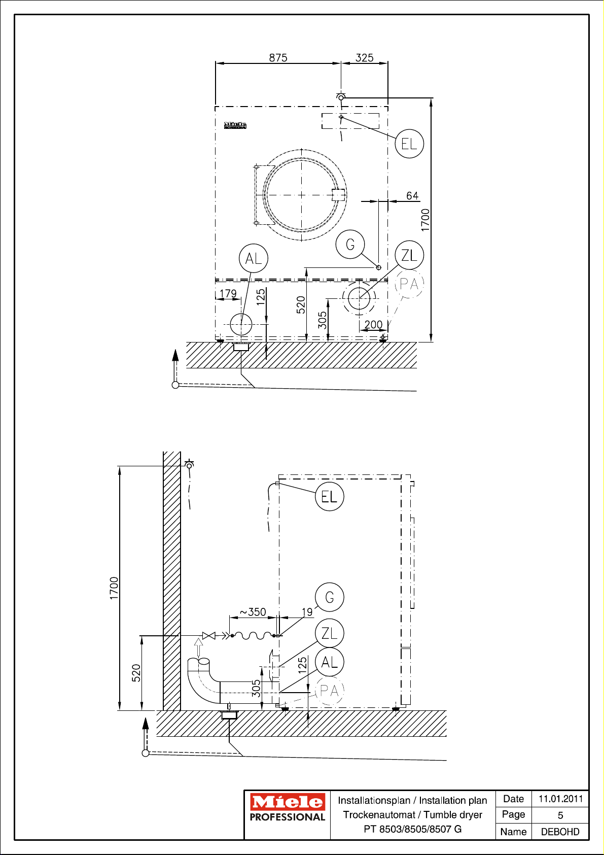
Machine connections:
Installationsplan / Installation plan: PT 8503/8505/8507
Datum / Date: 12.01.2011 Seite / Page: 8
Page 9
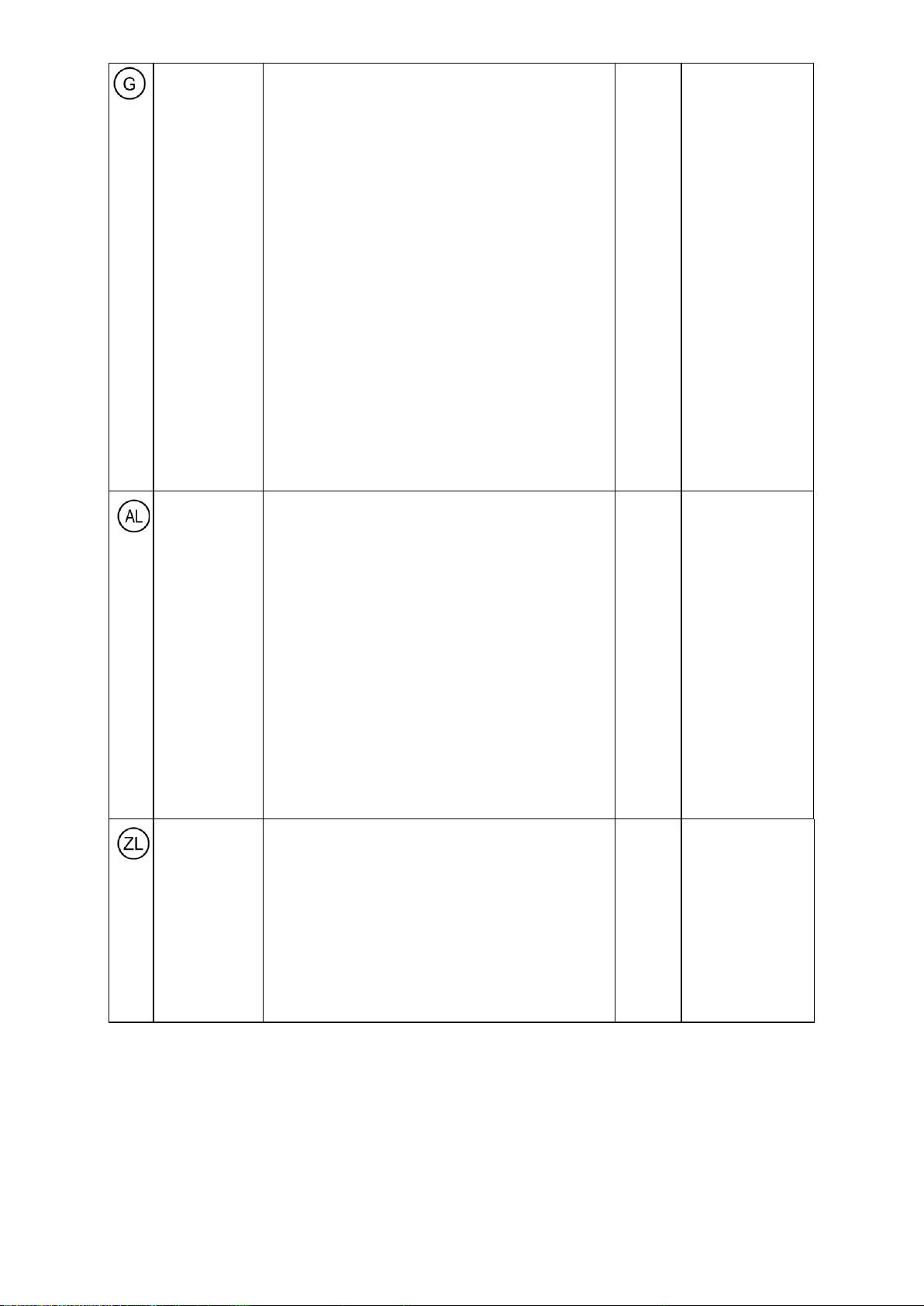
Gas connection
Nominal heat rating
kW
30
Machine-side connection according to ISO 7-1
Inch
½“
Length of connection hose (supplied)
mm
350
Stopcock to be provided on site.
Use of gas plug connection is not permissible on account of
restricted flow volume with respect to heater rating.
Natural gas
Connection thread (on site) schwanken)
Inch
½" internal thread
Connection pressure according to DIN EN 437
cf. operating and installation instructions
Liquid gas
Connection thread (on site) schwanken)
Inch
½" internal thread
or alternatively:
On-site connection with high-precision steel pipe accord-
ing to DIN 2391/DIN2393, with smooth pipe end,
DN
12
Min. connection length
mm
40
Connection sleeve ½" × ⅜" and ⅜" threaded union × DN
12 for steel pipe supplied with machine. ⅜" × DN 12 threaded union for steel pipe.
Connection pressure according to DIN EN 437
cf. operating and installation instructions
Connection to gas supply must comply with national
regulations.
Note installation instructions for gas-heated Miele tumble
dryers.
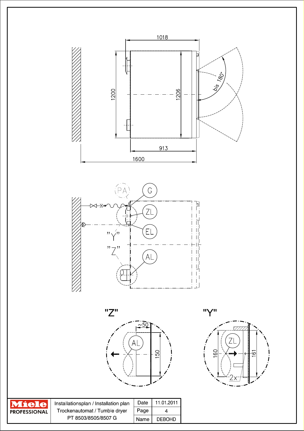
Waste air/gas
Max. nominal air flow in vented mode (PT 8507 only)
m³/h
1010
Nominal air flow (PT 8503/8505 only)
m³/h
940
Max. permissible pressure loss
Pa
300
Connection on machine side (ext. diameter)
mm
150
Connection pipe provided on site (int. diameter)
mm
150
Max. temperature
°C
80
This tumble dryer is a gas-burning machine without a flowoperated safety device with fan downstream of heat
exchanger.
Technical design: B22 (as standard)
Waste gas pipework must be pressure-tight.
Waste gas connections should be performed in accordance
with national and local regulations and may require approval.
Note installation instructions for gas-heated Miele tumble
dryers.
As relative humidity inside the vent ducting can be as high as
100%, suitable measures must be taken to prevent a
backflow of condensate into the machine.
Air intake
Standard connection: Air intake from installation site
Unobstructed air intake into room recommended (corresponding to 3 times the vent cross-section of machine)
cm²
531
A sufficient supply of fresh air should be ensured to
replace the air extracted.
Alternative connection: Ducted air intake (from outside
building)
Connector on machine (int. diameter)
mm
161
Connection pipe provided on site (ext. diameter)
mm
160
Lid removal exposes live components! For safety reasons,
the pipe connected for central air intake should be at least
900 mm long and secured using two screws.
Installationsplan / Installation plan: PT 8503/8505/8507
Datum / Date: 12.01.2011 Seite / Page: 9
Page 10
Fittings (supplied)
Without plinth
2 × clamps
2 × screws DIN 571 (Ø × length)
mm
6 × 40
2 × rawl plugs (Ø × length)
mm
10 × 50
Machine must be bolted to the floor!
Fixing materials for a floating screed floor are to be provided
on site.
On concrete platform
2 × clamps
2 × screws DIN 571 (Ø × length)
mm
6 × 40
2 × rawl plugs (Ø × length)
mm
10 × 50
Machine must be bolted to the floor!
Fixing materials for a floating screed floor are to be provided
on site.
Machine data
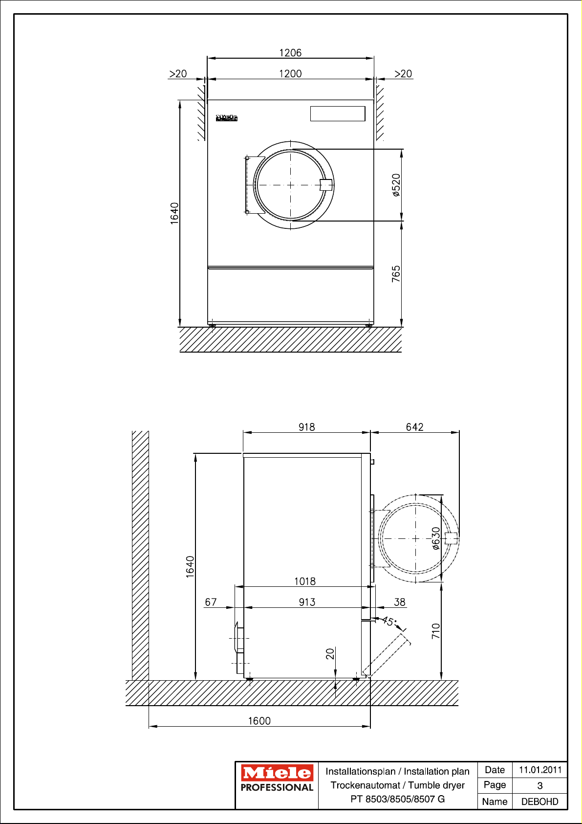
Unit width
mm
1206
Machine depth
mm
1018
Unit height
mm
1640
Casing width
mm
1200
Casing depth
mm
913
Minimum width of delivery access to installation site
mm
1030
Recommended rear wall gap (measured to front of machine)
mm
1600
Min. wall gap (to rear edge of lid)
mm
500
Net weight
kg
239
Dynamic floor load, max.
N
2712
Average heat dissipation
(dependent on ambient room temperature and programme
selected)
W
813
A Noise level
dB (A)
72.2
A Sound pressure level
(measured at a distance of 1 m from the machine and at a
height of 1.6 m)1 m
dB (A)
60
Installation should only be carried out by authorised fitters in accordance with valid regulations!
Observe installation instructions when installing machine! All rights reserved! Measurements in mm.
Installationsplan / Installation plan: PT 8503/8505/8507
Datum / Date: 12.01.2011 Seite / Page: 10
Page 11
Technische gegevens
Droogautomaat:
Verwarmingssoort:
PT 8503/8505/8507
Gas (G)
Legenda:
Geheel omcirkelde afkortingen betekenen:
aansluiting vereist
nl - NL
Niet geheel omcirkelde afkortingen betekenen:
optioneel of afhankelijk van het apparaat is aansluiting vereist
BS
Betonnen sokkel
De betonsoort en de stevigheid moeten geschikt zijn voor de
belasting die de automaat uitoefent. Een aanwezige betonnen
sokkel moet goed aan de ondergrond hechten!
Hoogte aanbevolen
mm
100
Hoogte minimaal
mm
50
Breedte minimaal
mm
1.200
Diepte minimaal
mm
1.100
Elektrische
aansluiting
1. Standaardspanning (af fabriek)
V 3N AC 380 - 415
Frequentie
Hz
50
Aansluitwaarde
kW
1,3
Zekering
A 3 × 10
Aansluitkabel, draaddoorsnede, minimaal
mm²
5 × 1,5
Kabelwartel
M 25
De aansluitkabels worden niet bijgeleverd.
De elektrische aansluiting dient volgens de nationale en
plaatselijke voorschriften te worden uitgevoerd.
Het is aan te bevelen het apparaat op een vergrendelbare
contactdoos aan te sluiten (volgens NEN-EN-IEC 60309 en
NEN-EN-IEC 60947) waarmee het apparaat met alle polen
van de netspanning kan worden losgekoppeld, zodat de
elektrische veiligheid eenvoudig kan worden gecontroleerd.
Bij een vaste aansluiting moet men alle polen via de installatie
kunnen loskoppelen.
De contactdoos of de schakelaar moet ook na de plaatsing
van het apparaat zichtbaar en goed toegankelijk zijn.
Aarding
Aansluitstuk (buitenschroefdraad)
mm
10 × 35
met ringen en moer
M
10
Toebehoren worden niet bijgeleverd.
De machine moet volgens de daarvoor geldende
voorschriften worden geaard!
Opties/toebehoren:
Aansluitingen:
Installationsplan / Installation plan: PT 8503/8505/8507
Datum / Date: 12.01.2011 Seite / Page: 8
Page 12
Gasaansluiting
Nominaal vermogen
kW
30
Gasaanluiting machinezijdig volgens ISO 7-1
inch/Zoll
½“
Lengte aansluitslang (bijgeleverd)
mm
350
De afsluitkraan moet ter plaatse beschikbaar zijn.
Vanwege de te geringe doorstroomhoeveelheid is het bij het
aangegeven verwarmingsvermogen niet toegestaan een
gascontactdoos te gebruiken.
Aardgas
Slangkoppeling ter plaatse
inch/Zoll
½“ binnenschroefdraad
Aansluitdruk volgens DIN EN 437,
zie gebruiksaanwijzing/installatiehandleiding
Vloeibaar gas
Slangkoppeling ter plaatse
inch/Zoll
½“ binnenschroefdraad
of alternatief:
Aansluiting met stalen buis volgens DIN 2391/DIN 2393
(ter plaatse), met gladde buis eindigend.
DN
12
Aansluitlengte, min.
mm
40
Overgangsmof ½“ × ⅜“ en schroefkoppeling ⅜“ × DN 12
voor stalen buis bijgeleverd. schroefkoppeling ⅜“ × DN 12 voor de stalen buis.
Aansluitdruk volgens DIN EN 437,
zie gebruiksaanwijzing/installatiehandleiding
De gasaansluiting dient volgens de nationale en plaatselijke
voorschriften te worden uitgevoerd.
Zie hiervoor ook de installatie-instructies voor gasverwarmde
Miele-droogautomaten.
Luchtafvoer/
rookgas
Nominale volumestroom (max.) bij luchtafvoer (alleen PT
8507)
m³/uur
1010
Nominale volumestroom, max. (alleen PT 8503/8505)
m³/uur
940
Drukverlies max. toegestaan
Pa
300
Aansluittuit machinekant (buitendiameter)
mm
150
Aansluitbuis ter plaatse (binnendiameter)
mm
150
Temperatuur max.
°C
80
De droogautomaat geldt als gasstookplaats zonder
stromingsbeveiliging met ventilator achter de
warmtewisselaar.
Type: B22 (bijgeleverd)
De afvoerleiding voor de rookgassen dient dan ook drukdicht
te zijn.
De rookgasaansluiting dient volgens de nationale en
plaatselijke voorschriften te worden uitgevoerd. Hiervoor moet
(afhankelijk van de voorschriften) een vergunning worden
aangevraagd c.q. een keuring worden uitgevoerd.
Zie hiervoor ook de installatie-instructies voor gasverwarmde
Miele-droogautomaten.
Omdat de relatieve luchtvochtigheid in de afvoer tot 100%
kan bedragen, moet met geschikte maatregelen worden
voorkomen dat terugstromende condens in het apparaat
terechtkomt.
Luchttoevoer
Standaardaansluiting: Toevoer uit de ruimte waar de machine
staat opgesteld
Aanbevolen vrije diameter luchttoevoer in de ruimte (is 3x
de diameter van de luchtafvoer van het apparaat)
cm²
531
Er moet voldoende luchttoevoer zijn naar de ruimte waar
het apparaat staat opgesteld om de afgevoerde
luchthoeveelheid te compenseren.
Alternatieve aansluiting: Aansluiting luchttoevoer rechtstreeks
van buiten
Aansluiting machinezijdig (binnendiameter)
mm
161
Aansluitbuis ter plaatse (buitendiameter)
mm
160
Bij het verwijderen van het beschermdeksel komen delen vrij
die onder spanning staan. Om veiligheidsredenen moet op
het centrale luchtaanzuigpunt van de droogautomaat (over
een minimale lengte van 900 mm) een buis worden
geïnstalleerd die met twee schroeven moet worden beveiligd.
Installationsplan / Installation plan: PT 8503/8505/8507
Datum / Date: 12.01.2011 Seite / Page: 9
Page 13
Bevestiging
(bijgeleverd)
Zonder sokkel
2 bevestigingsprofielen
2 houtschroeven DIN 571 (Ø × lengte)
mm
6 × 40
2 pluggen (Ø × lengte)
mm
10 × 50
De machine moet beslist worden bevestigd!
Bevestigingsmateriaal voor speciale vloeren (bijv. met
geïsoleerde afdeklaag) wordt niet bijgeleverd.
Op betonnen sokkel
2 bevestigingsprofielen
2 houtschroeven DIN 571 (Ø × lengte)
mm
6 × 40
2 pluggen (Ø × lengte)
mm
10 × 50
De machine moet beslist worden bevestigd!
Bevestigingsmateriaal voor speciale vloeren (bijv. met
geïsoleerde afdeklaag) wordt niet bijgeleverd.
Gegevens
machine
Breedte
mm
1.206
Diepte
mm
1.018
Hoogte
mm
1.640
Breedte behuizing
mm
1.200
Diepte behuizing
mm
913
Breedte transportopening min. (binnenwerks)
mm
1.030
Aanbevolen afstand tot de wand (tot voorkant apparaat)
mm
1.600
Minimale afstand tot de wand (tot achterkant deksel)
mm
500
Nettogewicht
kg
239
Vloerbelasting bij gebruik (max.)
N
2712
Gemiddelde warmteafgifte aan de ruimte
(afhankelijk van omgevingstemperatuur en gekozen
programma)
W
813
A-gewogen geluidsvermogen
dB (A)
72,2
A-gewogen geluidsdruk, werkplekspecifiek
(afstand 1 m, hoogte 1,6 m)
dB (A)
60
De installatiewerkzaamheden mogen alleen door een erkend installateur worden uitgevoerd met inachtneming van alle van
toepassing zijnde voorschriften en normen!
Houdt u zich bij plaatsing van het apparaat beslist aan de montagehandleiding! Wijzigingen voorbehouden! Afmetingen in
mm.
Installationsplan / Installation plan: PT 8503/8505/8507
Datum / Date: 12.01.2011 Seite / Page: 10
 Loading...