

Page 1

G1000 / G2000 Dishwashers
Technical Information
TECHNICAL INFORMATION
G1000 / G2000 Dishwashers
1
Page 2

G1000 / G2000 Dishwashers
Technical Information
G1000 / G2000 Dishwasher - Table of Contents
WARNINGS AND SAFETY INFORMATION ......................................................................10
1.0 CONSTRUCTION AND DESIGN...............................................................................11
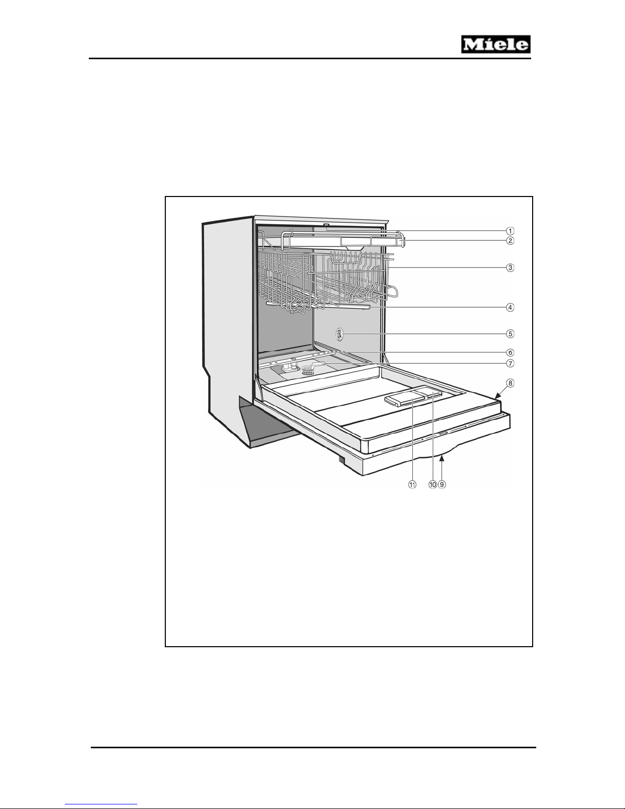
1.1 Appliance Overview................................................................................................................................................11
1.1.1 Appliance Overview – Typical Integrated Model........................................................................................11
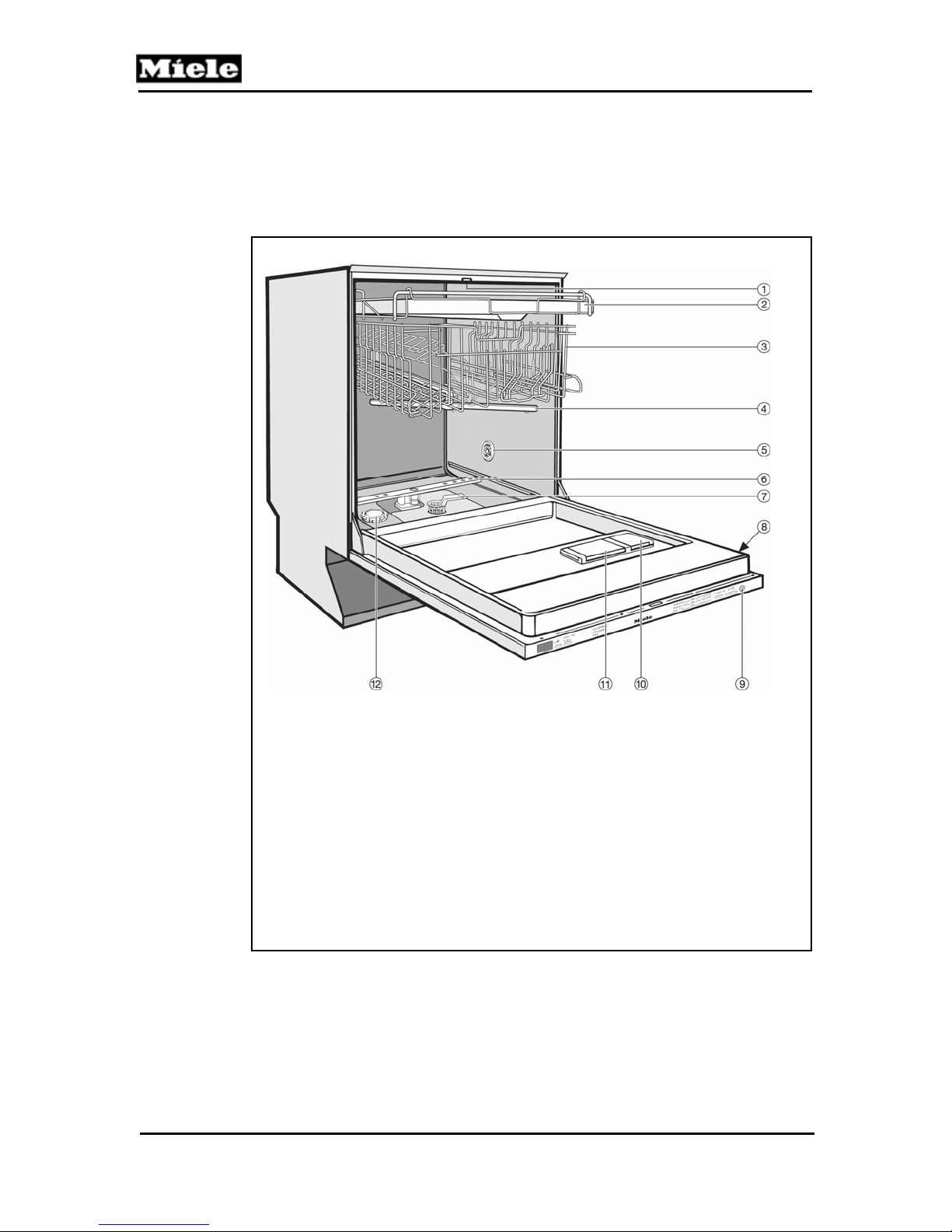
1.1.2 Appliance Overview – Typical Fully Integrated Model...............................................................................12
1.2 Controls Overview...................................................................................................................................................13
1.3 Types of Dishwashers..............................................................................................................................................14
1.3.1 Pre-Finished .................................................................................................................................................14
1.3.2 Integrated......................................................................................................................................................14
1.3.3 Fully Integrated ............................................................................................................................................14
1.4 Technical Data.........................................................................................................................................................15
1.4.1 Electrical Information...................................................................................................................................15
1.4.2 Plumbing Connections..................................................................................................................................16
1.4.2.1 Intake Connection..........................................................................................................................16
1.4.2.2 Drain Connection ..........................................................................................................................16
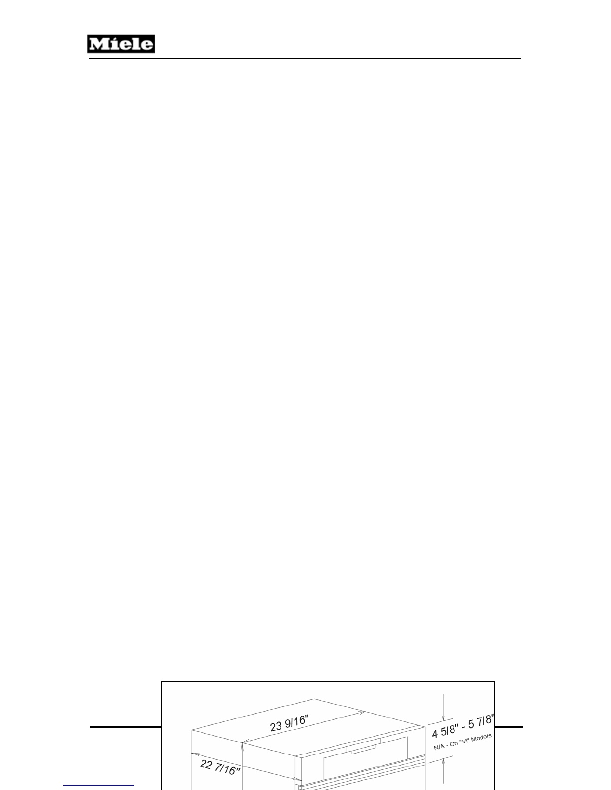
1.4.3 Dimensions...................................................................................................................................................16
1.5 Data Tag ..................................................................................................................................................................17
1.5.1 Data Tag - Location......................................................................................................................................18
1.5.2 Data Tag – Information................................................................................................................................18
1.6 Model Numbering....................................................................................................................................................18
1.6.1 Mode Numbering – Overview of USA Model Numbers..............................................................................19
1.7 Door Springs / Weights – Specifications.................................................................................................................20
1.8 Layout of Components (Typical).............................................................................................................................21
2.0 INSTALLATION .........................................................................................................22
3.0 COMMISSION AND OPERATION .............................................................................23
3.1 Door Handle / Lock – Prefinished & Integrated Models.........................................................................................23
3.2 Child Safety Lock....................................................................................................................................................23
3.3 Water Softener.........................................................................................................................................................24
3.3.1 Water Softener Salt – General Information..................................................................................................24
3.3.2 Water Softener Salt – Adding.......................................................................................................................24
3.4 General Operation....................................................................................................................................................26
3.4.1 Novotronic Controls.....................................................................................................................................26
3.4.2 Touchtronic & Navitronic Controls..............................................................................................................26
3.4.3 Fully Integrated (Incognito) (Vi) Controls...................................................................................................27
4.0 DESCRIPTION OF FUNCTION.................................................................................. 29
4.1 Cabinet Construction...............................................................................................................................................29
4.2 Water Intake ............................................................................................................................................................30
4.2.1 WaterProof System (WPS)...........................................................................................................................30
4.2.3 Water Inlet Mixer.........................................................................................................................................32
4.2.4 Water Inlet Mixer Without EGS...................................................................................................................35
4.2.5 Water Inlet Mixer wth EGS..........................................................................................................................36
4.2.6 Water Inlet Mixer during Reactivation.........................................................................................................37
4.2.7 Flow Meter B3/4, Water Intake Quantity.....................................................................................................38
2
Page 3

G1000 / G2000 Dishwashers
Technical Information
G1000 / G2000 Dishwashers - Table of Contents (Continued)
4.2.8 Sensor Softener............................................................................................................................................38
4.2.9 Electronically Controlled Water Hardness (EGS) .......................................................................................39
4.2.10 Intelligent Tab Function ..............................................................................................................................39
4.3 Water Circulation & Heating...................................................................................................................................41
4.3.1 Circulation Pump..........................................................................................................................................42
4.3.2 Circulation Pump - Speed Sensor and Load Sensing...................................................................................43
4.3.3 Heating.........................................................................................................................................................45
4.3.4 NTC Temperature Sensor, R30....................................................................................................................45
4.3.5 Heater Pressure Switch, B1/13.....................................................................................................................47
4.3.6 Turbidity Sensor (ECO Sensor III, Auto-sensor), B3/10..............................................................................48
4.3.7 Spray Arm Sensing.......................................................................................................................................50
4.3.8 Filter Combination with Micro Fine Filter...................................................................................................51
4.4 Dispensing...............................................................................................................................................................52
4.4.1 Combination Dispenser................................................................................................................................52
4.5 Drain System ...........................................................................................................................................................53
4.5.1 Drain Pump ..................................................................................................................................................53
4.6 Drying......................................................................................................................................................................54
4.6.1 Circulation Turbothermic Drying (active): UTT Version 1 .........................................................................54
4.6.2 Circulation Turbothermic Drying (active): UTT Version 2 .........................................................................56
4.6.3 Fan................................................................................................................................................................57
5.0 SERVICE AND MAINTENANCE................................................................................ 58
5.1 Housing....................................................................................................................................................................58
5.1.1 Side Panel – Removal..................................................................................................................................59
5.1.2 Drip Pan – Removal....................................................................................................................................59
5.2 Door.........................................................................................................................................................................61
5.2.1 Front Panel (GDU / Custom) – Removal ....................................................................................................61
5.2.2 Door Tension – Adjustment ........................................................................................................................62
5.2.3 Outer Door Panel – Removal.......................................................................................................................64
5.2.4 Fascia Panel Removal..................................................................................................................................65
5.2.5 Door Hinge - Removal ................................................................................................................................65
5.2.6 Combination Dispenser Unit - Removal......................................................................................................67
5.2.7 Cable Holder - Removal..............................................................................................................................68
5.2.8 Bottom Door Seal - Removal......................................................................................................................68
5.2.9 Locking Plate - Adjustment.........................................................................................................................69
5.2.10 Door Lock – Removal (Integrate Models)...................................................................................................70
5.2.11 Door Switch – Replacement (Integrated models)........................................................................................71
5.2.12 Fully Integrated (VI) Lock with Door Contact Switch Removal.................................................................72
5.2.13 Door lock emergency release – Activate (Fully Integrated)........................................................................72
5.3 Inner Cabinet...........................................................................................................................................................73
5.3.1 Door Seal - Replacement.............................................................................................................................73
5.3.2 Toe Kick (Plinth Removal) .........................................................................................................................74
5.3.3 Cover Plate - Removal.................................................................................................................................75
5.3.4 Connecting Strip (Lower Support) – Removal............................................................................................76
5.3.5 Multi-Plinth Removal (Door Tension Spring Housing) ..............................................................................77
5.3.6 Steam Condenser Removal..........................................................................................................................78
5.3.7 Fan Removal................................................................................................................................................78
5.3.8 Basket Runners - Removal..........................................................................................................................79
5.3.9 Water Level Check......................................................................................................................................80
5.4.1 WaterProof System (WPS) Restrictor – Replacement ................................................................................82
5.4.2 WaterProof System (WPS) - Removal ........................................................................................................83
3
Page 4

G1000 / G2000 Dishwashers
Technical Information
G1000 / G2000 Dishwashers - Table of Contents (Continued)
5.4.3 Flowmeter (circuit board) – Removal .........................................................................................................84
5.4.4 Top Spray Arm Removal.............................................................................................................................84
5.4.5 Middle Spray Arm Removal .......................................................................................................................84
5.4.6 Bottom Spray Arm Removal.......................................................................................................................85
5.4.7 Feed Pipe with Turbidity Sensor – Top Spray Arm, Removal....................................................................85
5.4.8 Feed Pipe – Middle Spray Arm, Removal...................................................................................................85
5.4.9 Spray Arm Sensor Removal........................................................................................................................85
5.4.10 Water Inlet Mixer with Resin Chamber – Removal....................................................................................86
5.4.11 EGS Valve Solenoid - Removal..................................................................................................................88
5.4.12 Reactivation Valve – Removal....................................................................................................................88
5.4.13 Salt Container - Removal ............................................................................................................................89
5.4.14 Circulation Pump - Removal.......................................................................................................................89
5.4.15 Circulation Pump - Service.........................................................................................................................91
5.4.15.1 Pump Cap Removal / Heater Element – Access.......................................................................92
5.4.15.2 Slide Shutter Removal ..............................................................................................................92
5.4.15.3 Drive Removal...........................................................................................................................93
5.4.15.4 Pump Impeller Removal ...........................................................................................................95
5.4.15.5 Pump Housing Rem oval...........................................................................................................95
5.4.15.6 Capacitor Removal....................................................................................................................95
5.4.15.7 Heater Pressure Switch Removal..............................................................................................95
5.4.15.8 Speed Sensor Removal..............................................................................................................95
5.4.16 Drain Pump Removal .................................................................................................................................96
5.4.17 Float Switch Removal................................................................................................................................96
5.4.18 Sump Removal ...........................................................................................................................................97
5.4.19 NTC Temperature Sensor Removal...........................................................................................................98
5.4.20 Filter Combination Dismantling.................................................................................................................99
5.4.21 Filter Combination Assembly (New Micro Fine Filter and Handle)........................................................100
5.4.22 Filter Combination Assembly (with Locking Piece)................................................................................101
5.5 Electronic Unit.......................................................................................................................................................103
5.5.1 Mains Switch Removal (Integrated).........................................................................................................104
5.5.2 Electronic Unit Holder Removal..............................................................................................................105
5.5.3 Electronic Unit Removal (Integrated) ......................................................................................................105
6.0 FAULT DIAGNOSIS .................................................................................................106
6.1 Diagnostic Modes – Overview .............................................................................................................................106
6.1.1 Water Hardness Setting – Checking and Programming ...............................................................................107
6.2 Advanta Series.......................................................................................................................................................107
6.2.1 Advanta Series - G2020................................................................................................................................107
6.2.1.1 G2020 - Programming Mode....................................................................................................107
6.2.1.2 G2020 - Service Mode..............................................................................................................112
6.2.1.3 G2020 Component Test – Information .....................................................................................115
6.2.2 Advanta Series – G2170...............................................................................................................................117
6.2.2.1 G2170 - Programming Mode ....................................................................................................117
6.2.2.2 G2170 - Service Mode..............................................................................................................124
6.2.2.3 G2170 Component Test – Information .....................................................................................127
6.3 Inspira Series .........................................................................................................................................................129
6.3.1 Inspira Series - G2140 & G2150..................................................................................................................129
6.3.1.1 G2140 / G2150 - Programming Mode ......................................................................................129
6.3.1.2 G2140 / G2150 Service Mode...................................................................................................134
6.3.1.3 G2140 / G2150 Component Test - Information........................................................................137
4
Page 5

G1000 / G2000 Dishwashers
Technical Information
G1000 / G2000 Dishwashers - Table of Contents (Continued)
6.3.2 Inspira Series - G1180 & G2180.................................................................................................................139
6.3.2.1 G1180 / G2180 - Programming Mode ......................................................................................139
6.3.2.2 G1180 / G2180 - Service Mode ................................................................................................146
6.3.2.3 G1180 / G2180 – Component Test............................................................................................149
6.4 Optima Series .......................................................................................................................................................151
6.4.1 Optima Series – G2420 & G2430.................................................................................................................151
6.4.1.1 G2420 / G2430 – Programming Mode.......................................................................................151
6.4.1.2 G2420 / G2430 - Service Mode Summary.................................................................................157
6.4.1.3 G2420 / G2430 Component Test ...............................................................................................160
6.4.2 Optima Series – G1470 & G2470...............................................................................................................162
6.4.2.1 G1470 / G2470 Programming Mode..........................................................................................162
6.4.2.2 G1470 / G2470 – Service Mode................................................................................................168
6.4.2.3 G1470 / G2470 Component Test ...............................................................................................170
6.5 Excella Series........................................................................................................................................................172
6.5.1 Excella Series – G2630................................................................................................................................172
6.5.1.1 G2630 Programming Mode........................................................................................................172
6.5.1.2 G2630 – Service Mode..............................................................................................................178
6.5.1.3 G2630 Component Test..............................................................................................................180
6.5.2 Excella Series – G2670 ................................................................................................................................183
6.5.2.1 G2670 Programming Mode........................................................................................................183
6.5.2.2 G2670 – Service Mode..............................................................................................................187
6.5.2.3 G2670 Component Test..............................................................................................................189
6.6 LaPerla - G2830....................................................................................................................................................192
6.6.1 G2830 - Program Mode ..............................................................................................................................192
6.6.2 G2830 – Service Mode...............................................................................................................................197
6.6.3 G2830 Component Test..............................................................................................................................199
6.7 Fault Code Summary............................................................................................................................................203
6.8 Fault Repair Summary..........................................................................................................................................204
6.8.1 No Power - Main Switch Is On ..................................................................................................................204
6.8.2 Display shows “Close Salt Reservoir Cap”................................................................................................204
6.8.3 Drain Pump Switches On and Off at Short Intervals..................................................................................204
6.8.4 Inlet / Drain LED Flashes and Lights up Alternately (Fully Integrated) ..................................................205
6.8.5 Dishwasher Program Can Be Selected But Not Started.............................................................................205
6.8.6 Dishwashing program interrupted, no fault indication...............................................................................205
6.8.7 Door does not close correctly.....................................................................................................................206
6.8.8 Condensation forms on adjacent cabinets...................................................................................................206
6.8.9 Noises during drying cycle.........................................................................................................................207
6.8.10 Foreign object in drain system....................................................................................................................207
6.8.11 Poor Drying Results....................................................................................................................................208
6.8.12 No Drying Or Drying Too Slow.................................................................................................................208
6.8.13 Water Present In Appliance And Is Not Bei n g Drai n ed Off.......................................................................210
6.8.14 Inlet/Drain LED Flashes During Water Intake, Dishwasher ends selected program. (F12, F13 or F19)....211
6.8.15 Wash Program Is Interrupted And Drain Pump Is Operated.......................................................................214
6.8.16 The program is not interrupted, but faults are logged into the fault memory..............................................220
5
Page 6

G1000 / G2000 Dishwashers
Technical Information
G1000 / G2000 Dishwashers - List of Figures
Figure 1-1: Appliance Overview (Typical Integrated Unit)............................................. 11
Figure 1-2: Appliance Overview (Typical Fully Integrated (Vi) Unit) .............................12
Figure 1-3: Pre-Finished Dishwasher............................................................................ 14
Figure 1-4: Integrated Dishwasher................................................................................ 14
Figure 1-5: Fully Integrated (Incognito) (Vi) Dishwasher............................................... 15
Figure 1-6: Dimensions ................................................................................................. 17
Figure 1-7: Data Tag Location ......................................................................................18
Figure 1-8: Data Tag Information .................................................................................. 18
Figure 1-9: Model Numbering .......................................................................................19
Figure 1-10: Layout of Components................................................................................ 21
Figure 2-1: Installation Manual (Typical) ....................................................................... 22
Figure 3-1: Door Handle Release .................................................................................23
Figure 3-2: Child Safety Lock........................................................................................23
Figure 3-3: Salt Container Release...............................................................................25
Figure 3-4: Filling the Salt Using the Built In Funnel..................................................... 25
Figure 3-5: Display (Main Menu)................................................................................... 26
Figure 3-6: Display (With Selected Program)................................................................ 26
Figure 3-7: Display (With Selected Options) ................................................................. 27
Figure 3-8: Display (Main Menu)................................................................................... 27
Figure 3-9: Display (With Selected Program)................................................................ 27
Figure 3-10: Display (With Selected Options) ................................................................. 28
Figure 4-1: Inner Cabinet .............................................................................................. 29
Figure 4-2: WaterProof System Intake Valves ..............................................................30
Figure 4-3: WaterProof System Flow Restrictor............................................................ 31
Figure 4-4: Water Inlet Mixer......................................................................................... 33
Figure 4-5: Inlet Mixer without EGS .............................................................................. 35
Figure 4-6: Inlet Mixer with EGS ................................................................................... 36
Figure 4-7: Inlet Mixer during Reactivation ...................................................................37
Figure 4-8: Water Intake and Circulation Paths ............................................................ 41
Figure 4-9: Circulation Pump – Water Paths................................................................. 42
Figure 4-10: Circulation Pump - Components................................................................. 44
Figure 4-11: Heater Pressure Switch Circuit................................................................... 47
Figure 4-12: Turbidity Sensor Circuit ..............................................................................48
Figure 4-13: Turbidity Sensor.......................................................................................... 49
Figure 4-14: Spray Arm Sensor ......................................................................................50
Figure 4-15: Filter Combination in Sump ........................................................................51
Figure 4-16: Combination Dispenser ..............................................................................52
Figure 4-17: Drying System UTT Version 1 .................................................................... 54
Figure 4-18: Drying System UTT Version 2 .................................................................... 56
Figure 5-1: Toe Kick (Plinth) Removal .......................................................................... 75
Figure 5-2: Door Tension Adjustment ........................................................................... 62
Figure 5-3: Side Panel Removal ................................................................................... 59
6
Page 7

G1000 / G2000 Dishwashers
Technical Information
G1000 / G2000 Dishwashers - List of Figures (Continued)
Figure 5-4: Door Seal with Door.................................................................................... 70
Figure 5-5: Door Seal Installation.................................................................................. 74
Figure 5-6: Drip Pan Removal....................................................................................... 60
Figure 5-7: Integrated Door Panel Screw Locations ..................................................... 62
Figure 5-8: Outer Door Panel Removal......................................................................... 64
Figure 5-9: Opening the Hinge Bracket......................................................................... 66
Figure 5-10: Front Hinge Retaining Screw...................................................................... 67
Figure 5-11: Side Hinge Retaining Screw ....................................................................... 67
Figure 5-12: Side Hinge Retaining Screw ....................................................................... 67
Figure 5-13: Dispenser Removal ....................................................................................68
Figure 5-14: Lower door seal holder ............................................................................... 69
Figure 5-15: Door Lock Removal .................................................................................... 71
Figure 5-16: Cover Plate Removal.................................................................................. 76
Figure 5-17: Connecting Strip Removal ..........................................................................77
Figure 5-18: Retaining Clip .............................................................................................80
Figure 5-19: Water Level Reference ............................................................................... 81
Figure 5-20: Tilting the Flow Restrictor ........................................................................... 83
Figure 5-21: Removing the Flow Restrictor..................................................................... 83
Figure 5-22: Water Intake Mixer Assembly and Related Components ...........................88
Figure 5-23: Circulation Pump and Related Components (Typical)................................ 91
Figure 6-3: Circuit test path for F11. ............................................................................210
Figure 6-4: F19 - Start rinse block water intake ........................................................... 212
Figure 6-5: F19 – Test routine...................................................................................... 213
Figure 6-6: Circuit test path for F24. ............................................................................216
Figure 6-7: Circuit test path for F-51 (initial state)........................................................ 217
Figure 6-8: Circuit test path for F-51 (testing state) .....................................................218
7
Page 8

G1000 / G2000 Dishwashers
Technical Information
G1000 / G2000 Dishwashers - List of Tables
Table 1-1: Controls Overview..........................................................................................................13
Table 1-2: Overview of US Model Numbers....................................................................................19
Table 1-3: Door Spring Summary ...................................................................................................20
Table 1-4: Panel weights/tension springs in delivery condition.......................................................20
Table 1-5: Panel weights/tension springs in customer service version...........................................20
Table 4-1: NTC Sensor Resistance Values ....................................................................................46
Table 6-1: Diagnostic Mode Overview by Series / Model Number................................................106
Table 6-2: Water Hardness: Standard setting: 15 gr/gal (15 °d)...................................................107
Table 6-3: G2020 Programming Mode Options (continued on Table 6-4) ....................................108
Table 6-4: G2020 Programming Mode Options (cont. from Table 6-3) (cont. on Table 6-5) ........109
Table 6.5: G2020 Programming Mode Options (cont. from Table 6-4) (cont. to Table 6-6). ........110
Table 6.6: G2020 Programming Mode Options (continued from Table 6-5) .................................111
Table 6-7: G2020 Service Mode Options (Continued on Table 6-8).............................................113
Table 6-8: G2020 Service Mode Options (continued from Table 6-7) ..........................................114
Table 6-9: G2170 Programming Mode Options (continued on Table 6-10) ..................................118
Table 6-10: G2170 Programming Mode Options (Cont. from Table 6-9) (Cont. on Table 6-11).....119
Table 6-11: G2170 Programming Mode Options (Cont. from Table 6-10) (Cont. on Table 6-12)...120
Table 6-12: G2170 Programming Mode Options (Cont. from Table 6-11) (Cont. on Table 6-13)...121
Table 6-13: G2170 Programming Mode Options (Cont. from Table 6-12) (Cont. on Table 6-14)...122
Table 6-14: G2170 Programming Mode Options (continued from Table 6-13)...............................123
Table 6-15: Service Mode (G2170) (Continued on Table 6-16)......................................................125
Table 6-16: Service Mode (G2170) (Continued from Table 6-15)...................................................126
Table 6-17: G2140 Program Mode Options (Continued on Table 6-18) .........................................130
Table 6-18: G2140 Program Mode Options (Cont. from Table 6-17) (Cont. on Table 6-19) ..........131
Table 6-19: G2140 Program Mode Options (Cont. from Table 6-18) (Cont. on Table 6-20) ..........132
Table 6-20: G2140 Program Mode Options (Continued from Table 6-19)......................................133
Table 6-21: G2140 Service Mode Options (Continued on Table 6-22)...........................................135
Table 6-22: G2140 Service Mode Options (Continued from Table 6-21)........................................136
Table 6-23: G1180 / G2180 Programming Mode Options (Continued on Table 6-24) ...................140
Table 6-24: G1180 / G2180 Programming Mode Options (Cont. from Table 6-23)
(Cont. on Table 6-25) .................................................................................................141
Table 6-25: G1180 / G2180 Programming Mode Options (Cont. from Table 6-24)
(Cont. on Table 6-26) .................................................................................................142
Table 6-27: G1180 / G2180 Programming Mode Options (Cont. from Table 6-26)
(Cont. on Table 6-28) .................................................................................................144
Table 6-28: G1180 / G2180 Programming Mode Options (Continued from Table 6-27) ................145
Table 6-29: G1180 / G2180 Service Mode (Continued on Table 6-30) ..........................................147
Table 6-30: G1180 / G2180 Service Mode (Continued from Table 6-29) .......................................148
Table 6-31: G2420 / G2430 Programming Mode Options (Continued on Table 6-32) ...................152
Table 6-32: G2420 / G2430 Programming Mode Options (Cont. from Table 6-31)
(Cont. on Table 6-33) .................................................................................................153
Table 6-33: G2420 / G2430 Programming Mode Options (Cont. from Table 6-32)
(Cont. on Table 6-34) .................................................................................................154
8
Page 9

G1000 / G2000 Dishwashers
Technical Information
G1000 / G2000 Dishwashers - List of Tables (Continued)
Table 6-34: G2420 / G2430 Programming Mode Options (Cont. from Table 6-33)
(Cont. on Table 6-35) .................................................................................................155
Table 6-35: G2420 / G2430 Programming Mode Options (Continued from Table 6-34) ................156
Table 6-36: G2420 / G2430 Service Mode Options (Continued on Table 6-37) .............................158
Table 6-37: G2420 / G2430 Service Mode Options (Continued from Table 6-36)..........................159
Table 6-38: G1470 / G2470 Programming Mode Options (Continued on Table 6-39) ...................163
Table 6-39: G1470 / G2470 Programming Mode Options (Cont. from Table 6-38)
(Cont. on Table 6-40) .................................................................................................164
Table 6-40: G1470 / G2470 Programming Mode Options (Cont. from Table 6-39)
(Cont. on Table 6-41) .................................................................................................165
Table 6-41: G1470 / G2470 Programming Mode Options (Cont. from Table 6-40)
(Cont. on Table 6-42) .................................................................................................167
Table 6-42: G1470 / G2470 Programming Mode Options (Continued from Table 6-41) ................167
Table 6-43: G1470 / G2470 Service Mode Options ........................................................................169
Table 6-44: G2630 Programming Mode Options (Continued on Table 6-45) .................................173
Table 6-45: G2630 Programming Mode Options (Cont. from Table 6-44) (Cont. on Table 6-46)...174
Table 6-46: G2630 Programming Mode Options (Cont. from Table 6-45) (Cont. on Table 6-47)...175
Table 6-47: G2630 Programming Mode Options (Cont. From Table 6-46) (Cont. on Table 6-48) .176
Table 6-48: G2630 Programming Mode Options (Continued on Table 6-47) .................................177
Table 6-49: G2630 Service Mode Options......................................................................................179
Table 6-50: G2670 Programming Mode Options (Continued on Table 6-51) .................................184
Table 6-51: G2670 Program Mode Options (Cont. from Table 6-50) (Cont. on Table 6-52) ..........185
Table 6-52: G2670 Programming Mode Options (Continued from Table 6-51) ..............................186
Table 6-53: G2670 Service Mode Options......................................................................................188
Table 6-54: G2830 Programming Mode Options (Continued on Table 6-55). ................................193
Table 6-55: G2830 Programming Mode Options (Cont. from Table 6-54) (Cont. on Table 6-56)...194
Table 6-56: G2830 Programming Mode Options (Continued from Table 6-55). .............................195
Table 6-57: G2830 Service Mode Options......................................................................................198
Table 6-58: Fault Code Summary ...................................................................................................203
9
Page 10

G1000 / G2000 Dishwashers
Technical Information
Warnings and Safety Information
Service and repair work should only be carried out by suitably qualified persons in
accordance with all appropriate local and national safety regulations.
Before any service work is started, the appliance must be disconnected from the
power supply.
If it is necessary to tip the machine when working on the lower areas, it may only be
tilted onto its back. On models with salt container in the sump, the following must be
performed:
Empty the water inlet mixer: Open the salt container cap briefly, reinstall the cap and
ensure it is firmly secured. Any remaining water should then be removed from the
cabinet.
Upon completion of any service procedures, a short wash program without load
should be run. This is to remove any salt residues that might be present and prevent
possible corrosion.
If the retaining nut to the salt container becomes loose during repair work, the salt
container can slip out of the connection to the water inlet mixer. Should this occur the
salt container must be dismantled. To avoid leaks and additional procedures ensure
the salt container is supported via the service opening.
Do not tilt the unit onto its right side, as this would cause water to run into the fan.
Many procedures will require the machine to be placed on its back. Care should be
taken to avoid damage to the water hoses and power cord.
For questions, concerns, clarifications or further assistance contact the Miele
Technical Support Center at 1-800-999-1360.
10
Page 11
G1000 / G2000 Dishwashers
1.0 Construction and Design
1.1 Appliance Overview
1.1.1 Appliance Overview – Typical Integrated Model
1 Upper Spray Arm (Not Visible)
2 Cutlery Tray (Depending On Model)
3 Upper Basket
4 Middle Spray Arm
5 Air Inlet For Drying (Depending On Model)
6 Lower Spray Arm
7 Filter Combination
8 Data Plate
9 Child Safety Lock In The Door Handle (Not Visible)
10 Rinse Aid Reservoir
11 Dual Compartment Detergent Dispenser
Figure 1-1: Appliance Overview (Typical Integrated Unit)
Technical Information
11
Page 12
G1000 / G2000 Dishwashers
Technical Information
1.1.2 Appliance Overview – Typical Fully Integrated Model
1 Upper Spray Arm (Not Visible)
2 Cutlery Tray (Depending On Model)
3 Upper Basket
4 Middle Spray Arm
5 Air Inlet For Drying (Depending On Model)
6 Lower Spray Arm
7 Filter Combination
8 Data Plate
9 Optical Interface
10 Rinse Aid Reservoir
11 Dual Compartment Detergent Dispenser
12 Salt Container
Figure 1-2: Appliance Overview (Typical Fully Integrated (Vi) Unit)
12
Page 13
G1000 / G2000 Dishwashers
1.2 Controls Overview
Controls on Miele dishwashers are categorized into four (4) types:
Control Type Description
Table 1-1: Controls Overview
Novotronic Each Novotronic model dishwasher can be operated with a single
knob. Surface mounted design technology (SMD) allows Miele
Novotronic components to be extremely durable and reliable.
These controls are capable of performing hundreds of tasks, which
cannot be handled by mechanical components.
Touchtronic This series of Miele dishwashers is operated by pushing a single
button – no separate temperature or drying selections – just turn
the machine on, select a program and Miele does the rest. All
models include a diverse group of wash programs for multiple
cleaning needs. Models are designed to maximize cleaning results
and optimize water and energy conservation.
Incognito (Fully
Integrated) (Vi)
Navitronic The Navitronic Touch Display consists of two electronic boards
The Incognito (fully integrated) series dishwashers have the
program controls located on the top edge of the door; and are
accessed while the door is open. Neither seen nor heard, the Miele
Incognito Series OCI (Optical cycle Indicator) allows you to see the
progress of the dishwasher cycle by way of a red light, which is
steady or flashing depending on the status of the cycle.
located behind the control panel. The front program electronic
board contains pad sensors, which respond to finger contact. Three
touch pad sensors are present on each side of the display to
control the menu items displayed next to them (indicated by a small
arrow) within the display area. During operation the display will
show:
The program name
The current time of day
The program sequence
The approximate remaining time
Faults and messages
Technical Information
13
Page 14

G1000 / G2000 Dishwashers
Technical Information
1.3 Types of Dishwashers
1.3.1 Pre-Finished
Figure 1-3: Pre-Finished Dishwasher
The pre-finished construction consist of a pre-assembled door panel and control
panel; making it an ideal replacement unit. Available in white, black or stainless steel.
1.3.2 Integrated
Figure 1-4: Integrated Dishwasher
Integrated dishwashers ship with a separate control panel, and optional GDU (door)
panel. Every Integrated dishwasher ships with a bracket for installing a custom
cabinet panel. The use of separate components allows for a truly customized
installation.
1.3.3 Fully Integrated
14
Page 15

G1000 / G2000 Dishwashers
Figure 1-5: Fully Integrated (Incognito) (Vi) Dishwasher
Fully Integrated Dishwashers are designed to blend into the surrounding cabinetry.
The operator controls are only available when door is opened. Each dishwasher is
shipped with a bracket for securing a custom cabinet panel. An optional Miele
stainless steel SCVi panel is also available.
1.4 Technical Data
1.4.1 Electrical Information
Power Requirements: 120 VAC, 60 Hz
Rated Load: 12.5 A / 1500 W (typical)
Circuit breaker: 15 AMPS
The appliance is equipped with a 4 ft power cord and molded NEMA 515 plug; for
connection to a NEMA 5-15R receptacle (120VAC, 15 Amp, 3 prong, grounded
outlet).
It is recommended that the power outlet for the appliance be installed on the wall
(within the cabinets), adjacent to under counter space where the appliance is
installed.
Ensure the cabinets contain no rough edges that could damage the power cord or
drain hose. If metal cabinets are used, ensure a rubber grommet is installed around
the opening.
Always exercise care when sliding the dishwasher in or out, to prevent damaging the
power cord and / or hoses.
Hard Wire Electrical Connection
Connections: L1 (Black) to L on terminal block, N (White) to N on terminal block,
Technical Information
15
Page 16
Technical Information
GND To ground connector.
Hard wiring the dishwasher should only be done if required by electrical code.
Do not cut the plug off the power supply cord / plug and connect it directly to the
house wiring under any circumstances. This voids the warranty.
For hard wiring, the power cord must be removed from the appliance by
disconnecting the cord from the terminal box located at the lower left front of the
dishwasher, behind the Toekick and Service Panel. Pass the permanent power
supply cable through the strain relief and secure it directly to the terminal box.
THIS APPLIANCE MUST BE GROUNDED
1.4.2 Plumbing Connections
1.4.2.1 Intake Connection
The appliance is equipped with a five (5) foot long Double WaterProof System Intake
Hose; equipped with a ¾ inch female hose connection; for connection to a ¾ inch
male hose thread water supply valve.
1.4.2.2 Drain Connection
The appliance is equipped with a five (5) foot long Drain Hose for connection to a ¾
inch drain nipple.
1.4.3 Dimensions
G1000 / G2000 Dishwashers
16
Page 17

G1000 / G2000 Dishwashers
Figure 1-6: Dimensions
For the latest product specifications, including product dimensions visit: Miele.com
1.5 Data Tag
Technical Information
17
Page 18
Technical Information
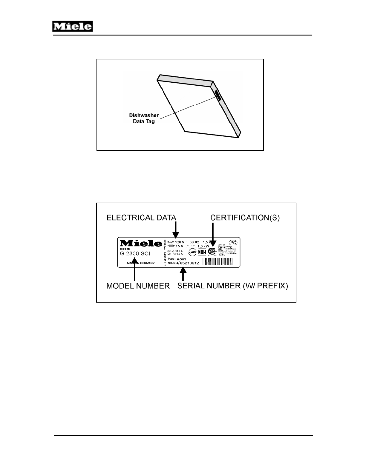
1.5.1 Data Tag - Location
Figure 1-7: Data Tag Location
1.5.2 Data Tag – Information
Figure 1-8: Data Tag Information
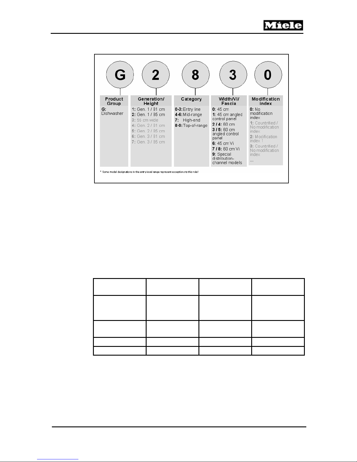
1.6 Model Numbering
G1000 / G2000 Dishwashers
18
Page 19
G1000 / G2000 Dishwashers
Figure 1-9: Model Numbering
1.6.1 Mode Numbering – Overview of USA Model Numbers
Advanta Series
Inspira Series
Optima Series
Excella
LaPeral
G2020
G2020SC
G2140
G2140SC
G2140i
G2420SCi G2430SC
G2170Vi
-
G2170SCVi
G2150 G2180Vi
G2150SC G2180SCVi
G1180SCvi
G2470SCVi
G2430SCi
G1470SCVi
G2630SCi G2670SCi G2830 - -
Technical Information
Table 1-2: Overview of US Model Numbers
19
Page 20
G1000 / G2000 Dishwashers
Technical Information
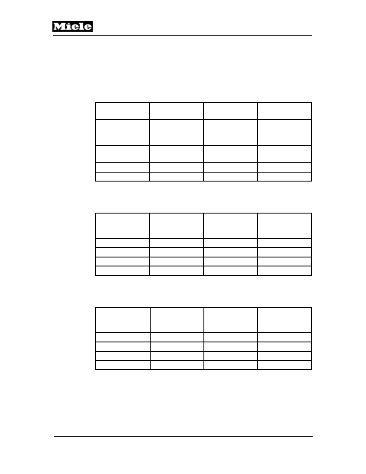
1.7 Door Springs / Weights – Specifications
Springs should always be installed in matching pairs
Model Color Tensile strength
(N)
G1xxx, free-
Orange Approx. 230 150
standing, builtunder
G2xxx, built
Blue Approx. 290 157
under
G1xxx, (I) (VI) Uncolored Approx. 320 156
G2xxx, (I) (VI) Green Approx. 410 155
Table 1-3: Door Spring Summary
Door panel weights/tension springs – factory
Series
Color Max. weight of
Control panel
type
G1xxx I Synthetic fiber Uncolored 10
G1xxx I Stainless steel Uncolored 9
G2xxx I Synthetic fiber Green 13
G2xxx I Stainless steel Green 11
Table 1-4: Panel weights/tension springs in delivery condition
Door panel weights/tension springs - service installed versions
Series
Color Max. weight of
Control panel
type
G1xxx I Synthetic fiber Green 15
G1xxx I Stainless steel Green 14
G2xxx I Synthetic fiber - G2xxx I Stainless steel - -
Table 1-5: Panel weights/tension springs in customer service version
20
Length (mm)
front panel (Kg)
front panel (Kg)
Page 21
G1000 / G2000 Dishwashers
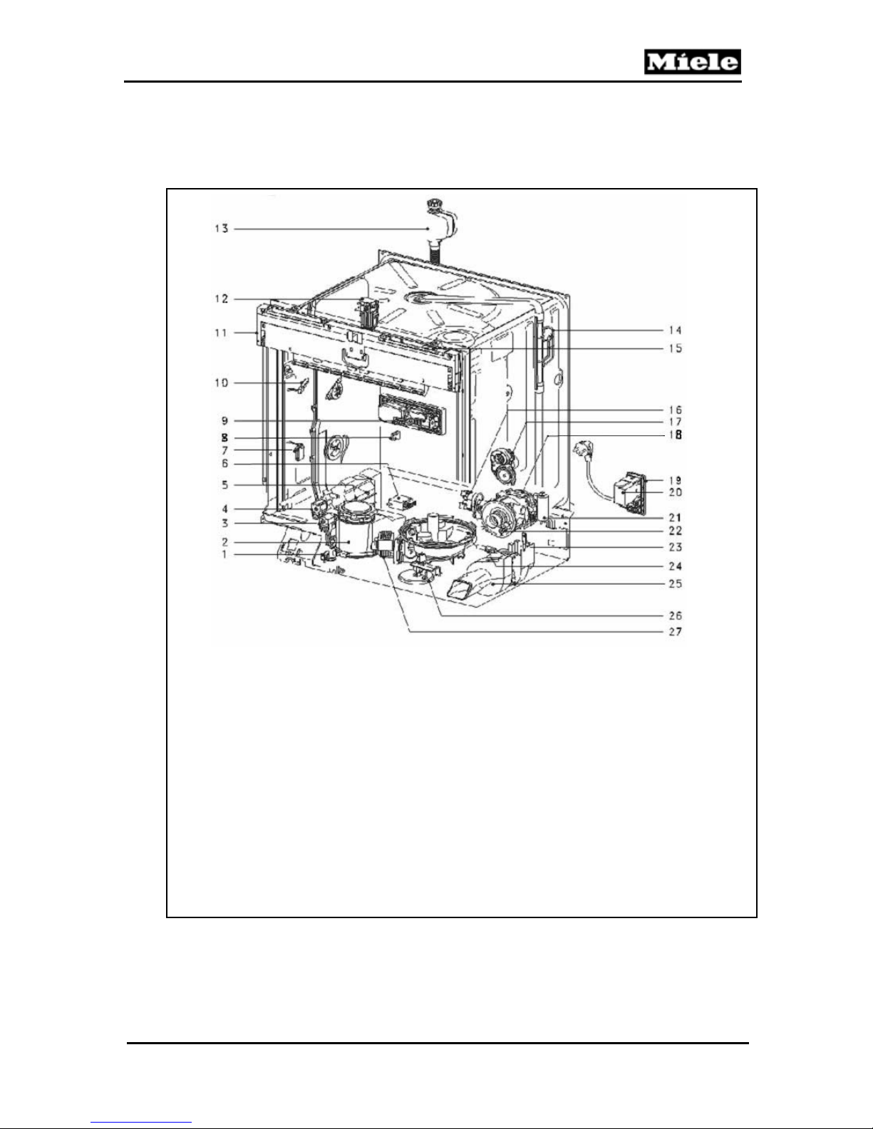
1.8 Layout of Components (Typical)
Figure 1-10: Layout of Components
1. Reed switch salt, B8/2 15. Main switch, S2
2. Salt reservoir 16. Heater Pressure switch, B1/13
3. Solenoid valve (reactivation) Y38 17. Slide shutter, M24 and B3/12
4. Solenoid valve (water hardness) Y5 18. Circulation pump (MPEW), M6
5. Sensor softener, 10N1 19. Main power socket, X3/1
6. Heater relay, K1/1 20. Interference suppressor, Z1
7. Spray arm sensing (middle) 4N1 21. Capacitor circulation pump, C6
8. Reed switch rinse aid, B8/1 22. Heater, R1
9. Combi-Dispenser solenoid, Y50 23. Speed sensor, B3/9
10. Flowmeter, B3/4 24. Temperature sensor (NTC), R30
11. Module tray electronic, 1N1 25. Fan, M2
12. Door contact switch, S24 26. Overflow reed switch, B8/3
13. Water Intake valve (water intake) Y2 27. Drain pump, M8
14. Turbidity sensor, B3/10
Technical Information
21
Page 22

Technical Information
2.0 Installation
Refer to the Residential Appliance Installation Manual.
Figure 2-1: Installation Manual (Typical)
G1000 / G2000 Dishwashers
22
Page 23

G1000 / G2000 Dishwashers
Technical Information
3.0 Commission and Operation
3.1 Door Handle / Lock – Prefinished & Integrated Models
To open the door: Press the release inside the door grip (Figure 3-1). To close the
door: Push door closed, until an audible click is heard.
Figure 3-1: Door Handle Release
Note
If the door is opened during operation, the dishwasher will stop
running. Once the door is closed the program will restart.
3.2 Child Safety Lock
Refer to Figure 3-2.
To lock the door: push the slider below the door grip to the right
To unlock the door: push the slider to the left. See Figure 3-2.
Figure 3-2: Child Safety Lock
23
Page 24
G1000 / G2000 Dishwashers
Technical Information
3.3 Water Softener
If your tap water hardness is above 8 grains per gallon (140 ppm), the
water should be softened.
If the Water Softener is needed (for select models only):
The water softener sets automatically to the local water hardness.
Note
The water hardness level can be programmed manually. See
Diagnostic Modes 6.1 or Operational Manual.
If the water softener is needed the salt reservoir must be filled – refer to 3.3.1
through 3.3.2 for details.
If the Water Softener is not needed (for select models only):
The “insufficient salt” message will turn off automatically.
Salt is not needed and should not be installed.
3 in 1 tablets and salt usage
When using 3 in 1 tablets (containing detergent, rinse aid, and water softener salt)
the “3 in 1” detergent setting should be selected. Use of 3 in 1 tablets will reduce salt
consumption of the machine to between a quarter and third of normal usage
amounts.
3.3.1 Water Softener Salt – General Information
Only use water softener salt specially formulated for dishwashers. Other salts may
contain insoluble additives that impair the Water Softener. The proper salt can be
purchased from Miele Technical Service Department.
3.3.2 Water Softener Salt – Adding
For models with salt reservoir located in bottom of the cabinet
1. Remove the Lower Basket.
2. Unscrew and remove the Salt Reservoir Cap located on the floor of the Wash
Cabinet.
3. If this is the first time salt is installed; add 2 quarts water.
4. Place a funnel over the Salt Reservoir.
5. Carefully fill reservoir with salt.
6. Clean any excess salt from the threads of the reservoir opening; and screw the
cap on firmly.
7. Run the” Rinse & Hold” program to remove any traces of salt from inside the
Wash Cabinet.
24
Page 25
G1000 / G2000 Dishwashers
The Salt Reservoir holds approximately 4.5 lbs (2 kg) of salt
For models with salt reservoir located on the inner door
1. Open door and hold at an angle, so that the salt container can be completely
filled.
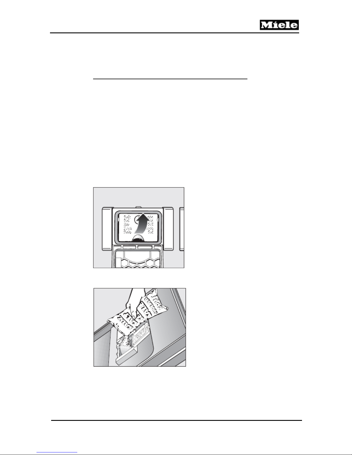
2. Open salt reservoir by pressing the button in the direction of the arrow
until the flap springs open - as shown in Figure 3-3.
3. Open the built in funnel, carefully fill with salt until water runs out.
4. Clean any excess and/or spilled salt.
5. Close the funnel and lid firmly.
6. Run the “Rinse & Hold” program to remove any traces of salt from inside the
wash cabinet. Should the display shows “Insufficient salt”, refill the salt after the
program has finished. Confirm with “OK”. The message will clear from the
display.
The salt container holds approx. 2.2 lbs. (1 Kg) of salt.
Figure 3-3: Salt Container Release
Figure 3-4: Filling the Salt Using the Built In Funnel
Technical Information
25
Page 26

Technical Information
3.4 General Operation
3.4.1 Novotronic Controls
1. Ensure the Spray Arms are not blocked.
2. Close the door.
3. Turn on the dishwasher. The “Start” Indicator will flash.
4. Select a wash program by turning the Program Selector to the left or right to the
desired wash program.
5. Press the “Start” button.
3.4.2 Touchtronic & Navitronic Controls
1. Ensure the Spray Arms are not blocked.
2. Close the door.
3. Turn on the dishwasher. The main menu shows in the display (Figure 3-5). If the
memory function is selected, the last selected program is displayed.
Figure 3-5: Display (Main Menu)
Note
Information about the selected program can be displayed by
touching the i control.
Select the desired program. The display changes to the program menu (Figure 3-6)
Figure 3-6: Display (With Selected Program)
G1000 / G2000 Dishwashers
26
Page 27

G1000 / G2000 Dishwashers
Select the desired options; a check will appear next to the option selected. See
Figure 3-7.
Figure 3-7: Display (With Selected Options)
When finished customizing the program, confirm with OK.
Select Start.
3.4.3 Fully Integrated (Incognito) (Vi) Controls
1. Open the door.
2. Ensure the Spray Arms are not blocked.
3. Turn on the dishwasher. The main menu shows in the display (Figure 3-8).
Figure 3-8: Display (Main Menu)
Note
Information about the selected program can be displayed by
touching the i control.
4. Select the desired program. The display changes to the program menu
(Figure 3-9).
Figure 3-9: Display (With Selected Program)
Technical Information
27
Page 28

Technical Information
5. Select the desired options; a check will appear next to the option selected.
See Figure 3-10.
Figure 3-10: Display (With Selected Options)
When finished customizing the program, confirm with OK.
Select Start. Close the door.
Note
For specific program details and further information on operating the
dishwasher refer to the model specific Operating Manual.
G1000 / G2000 Dishwashers
28
Page 29

G1000 / G2000 Dishwashers
4.0 Description of Function
4.1 Cabinet Construction
The inner cabinet is constructed of stainless steel (1.4301) welded onto four (4)
vertical U-section sub-frames. The cabinet is sound and heat-insulated with bitumen
and/or mineral wool matting.
Figure 4-1: Inner Cabinet
Technical Information
29
Page 30

Technical Information
4.2 Water Intake
4.2.1 WaterProof System (WPS)
The Water Inlet Valve (Y2) consists of two (2) electro-mechanical valves mounted
within a waterproof box located at the water connection (end of the water intake
hose).
The valves are mounted in physically and electrically in series to ensure that if one
valve should fail (e.g. due to blockage caused by a foreign body) the water flow will
still be switched off by the other valve.
Figure 4-2: WaterProof System Intake Valves
G1000 / G2000 Dishwashers
30
Page 31
G1000 / G2000 Dishwashers
The WaterProof System (WPS) consists of a number of interdependent safety
features, which provide protection against water leakage.
1. Protection against solenoid valve leakage:
Each water intake is controlled by an inlet valve. If this valve cannot close
properly due to some defect or blockage by a foreign body, a second inlet valve
ensures that the water supply is shut off.
2. Protection against water intake hose leakage:
If a leakage occurs, water flows along an outer hose sleeve surrounding the
intake hose to the drip tray. Here a float switch then acts to switch off a microswitch, which closes the inlet valves to cut off the water supply.
3. Protection against dishwasher overflow:
If some defect has caused the water level in the appliance to rise so that it
overflows into the drip tray, and the water quantity sensor has also failed, the
float switch is activated. This switches off a micro- switch, which closes the inlet
valves to cut off the water supply. At the same time the drain pump is activated.
4. Protection against drain pump failure or blocked drain path:
In this case the water level in the appliance rises until it overflows into the drip
tray where the float switch is activated. This switches off a micro-switch, which
closes the inlet valves to cut off the water supply.
Warning
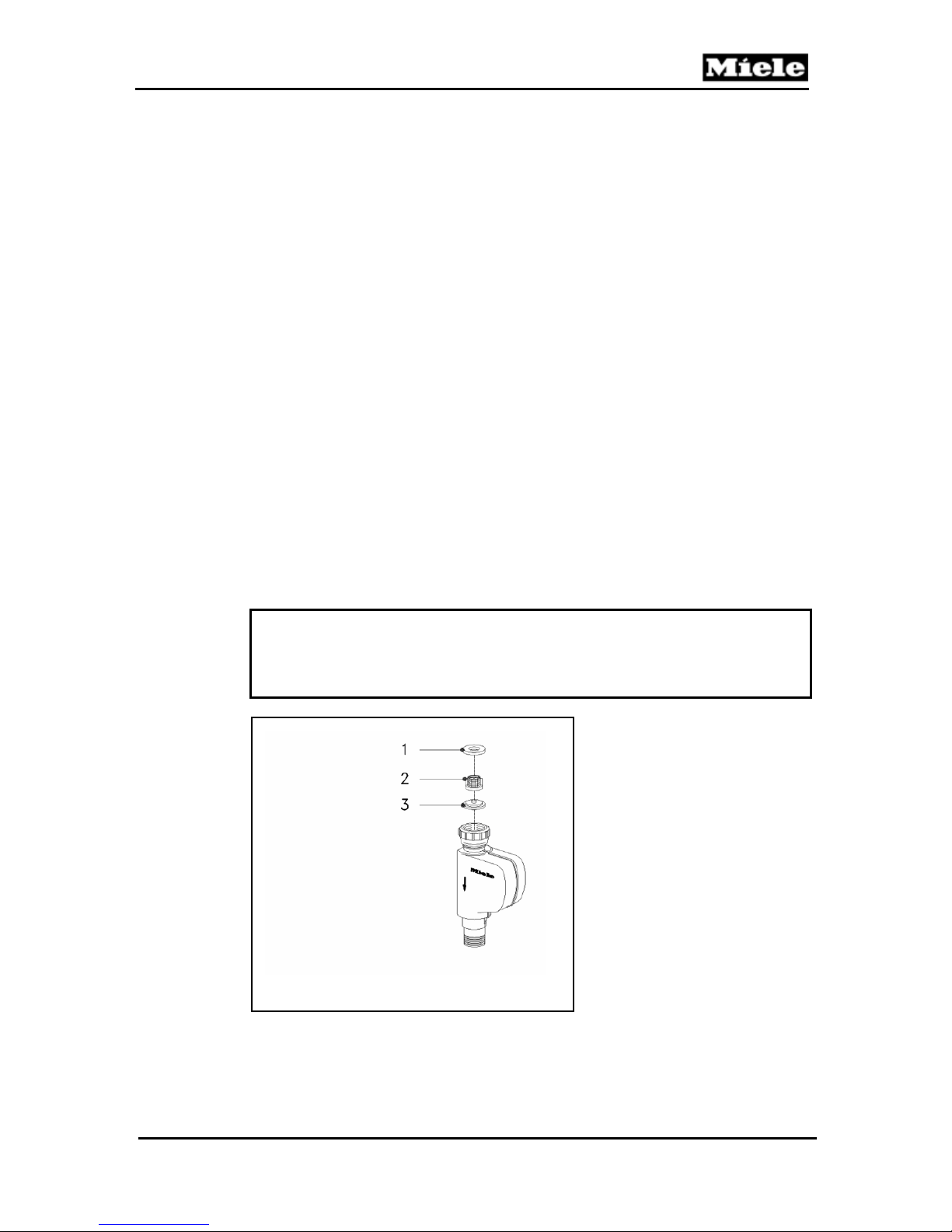
If the WaterProof System (WPS) is replaced, always ensure the
correct flow restrictor is installed.
1 Rubber Washer (Seal)
2 Filter
3 Flow Restrictor
Figure 4-3: WaterProof System Flow Restrictor
Technical Information
31
Page 32

Technical Information
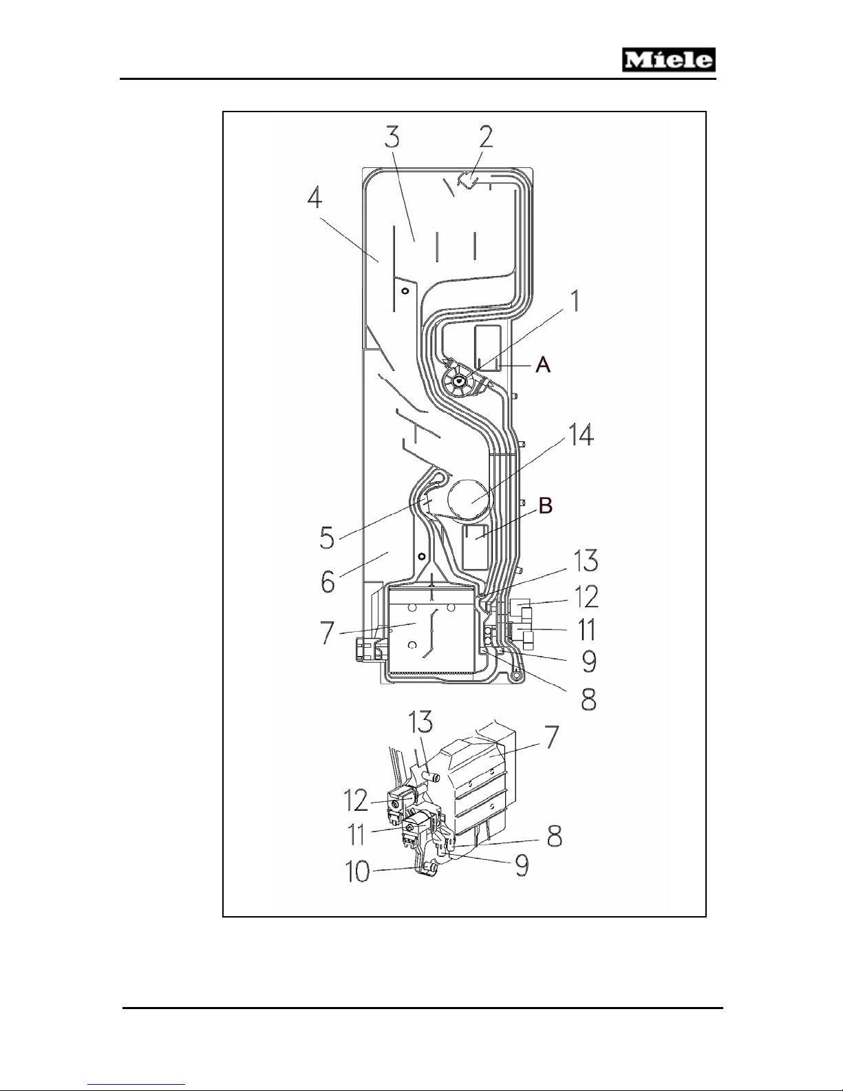
4.2.3 Water Inlet Mixer
Water is taken into the appliance via the inlet valve and the water inlet mixer, through
the ion exchanger (water softener) into the sump. The water softener resin (for
reactivation) is located at the bottom of the water inlet mixer. The assembly also
contains the EGS valve (for the electronically controlled water softener) reactivation
valve and a built in flow meter. The spray arm sensors are also positioned within the
assembly (on appropriate models that include spray arm sensors).
G1000 / G2000 Dishwashers
32
Page 33
G1000 / G2000 Dishwashers
Figure 4-4: Water Inlet Mixer
Technical Information
33
Page 34

Technical Information
Component List – Refer to Figure 4-4.
1. Flow Meter B3/4
2. Ball Valve
3. Water Reservoir – Softener Reactivation
4. Overflow
5. Non-return Device
6. Vent
7. Ion Exchanger
8. Water Outlet to Salt Container
9. Water Intake from Salt Container
10. Connection to Inlet Valve
11. Reactivation Valve
12. EGS Valve
13. Water Outlet to Sump
14. Cabinet Water Inlet
A. Middle Spray Arm Sensor
B. Lower Spray Arm Sensor
G1000 / G2000 Dishwashers
34
Page 35
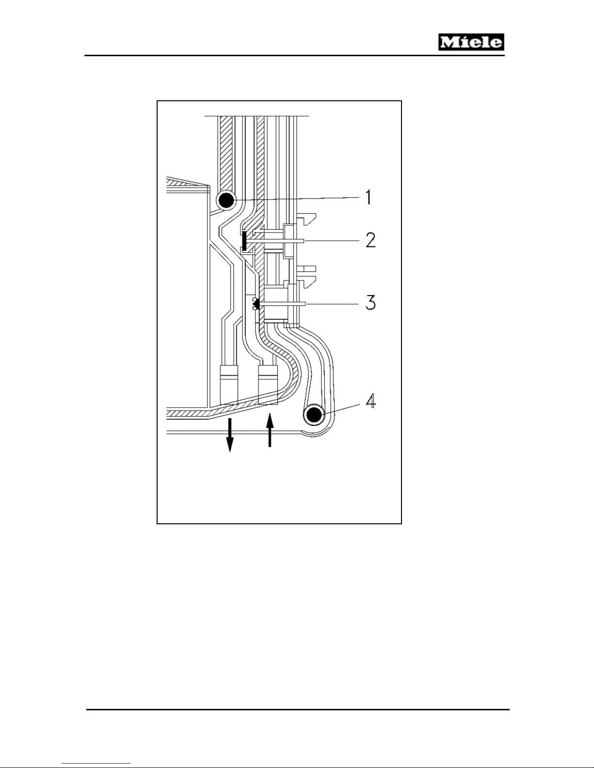
G1000 / G2000 Dishwashers
4.2.4 Water Inlet Mixer Without EGS
1. Water Outlet to Sump
2. EGS Valve not activated
3. Reactivation Valve
4. Connection to Inlet Valve
Figure 4-5: Inlet Mixer without EGS
Technical Information
35
Page 36
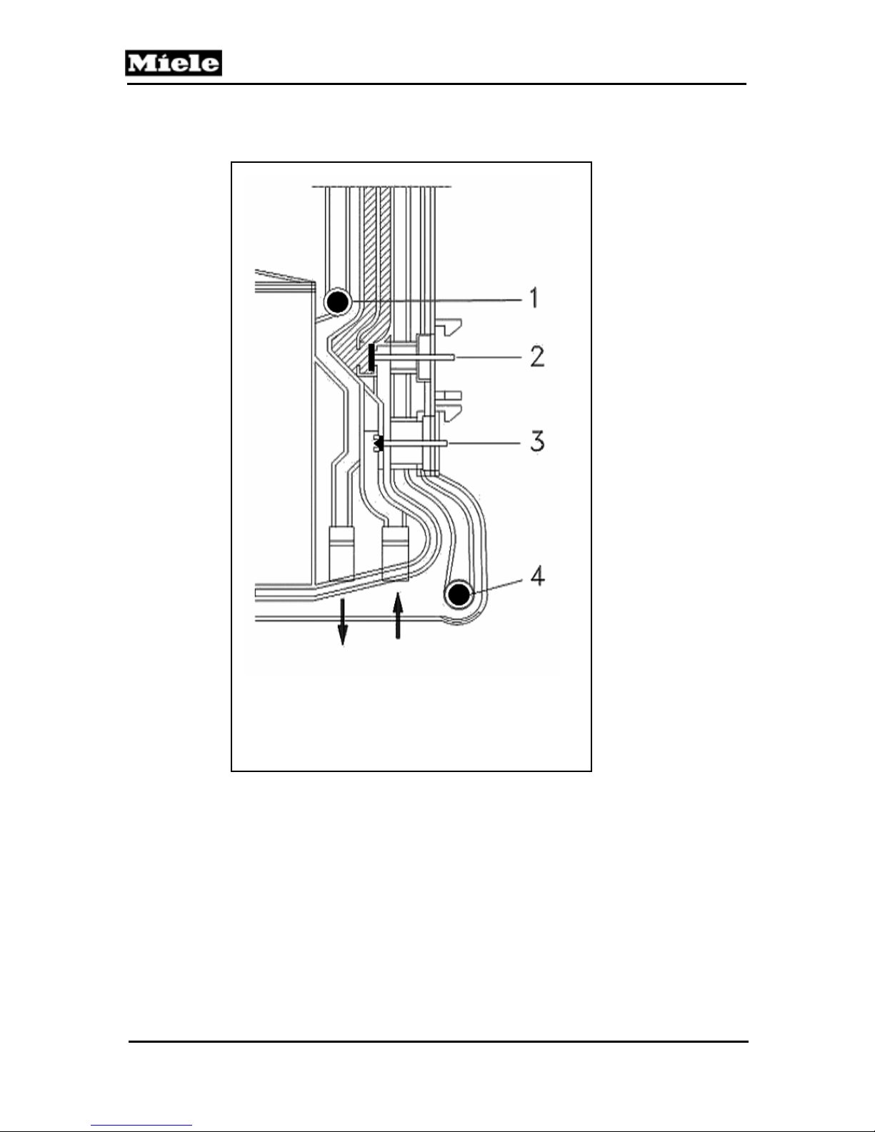
G1000 / G2000 Dishwashers
Technical Information
4.2.5 Water Inlet Mixer wth EGS
1. Water Outlet to Sump
2. EGS Valve activated
3. Reactivation Valve
4. Connection to Inlet Valve
Figure 4-6: Inlet Mixer with EGS
36
Page 37
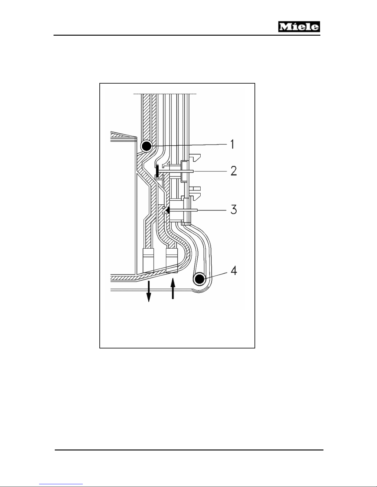
G1000 / G2000 Dishwashers
4.2.6 Water Inlet Mixer during Reactivation
1. Water Outlet to Sump
2. EGS Valve
3. Reactivation Valve open
4. Connection to Inlet Valve
Figure 4-7: Inlet Mixer during Reactivation
37
Technical Information
Page 38

G1000 / G2000 Dishwashers
Technical Information
4.2.7 Flow Meter B3/4, Water Intake Quantity
A Flow Meter B3/4 integrated in the Water Inlet Mixer monitors the water intake
quantity. The water flow is measured in the hard water area.
A permanent magnet located in the Flow Meter axle activates an external reed
switch each time the axle rotates. The pulses supplied by the reed switch are
registered by the electronic unit and compared with a target value stored in memory
for the particular program or program step in operation. For each liter of water,
approx. 200 pulses should be registered. When the target value (maximum number
of pulses) is reached, the water intake step is stopped. If the target value has not
been reached after 4 min, the program is interrupted and the Drain Pump operates.
Then, depending on the model, the Inlet/Drain LED flashes or fault code F13 is
displayed, see Fault code F13, 6.8.14.
Note
For precise details regarding permissible minimum flow pressure, see
the appropriate operating/installation instructions.
4.2.8 Sensor Softener
If there is a break in data transfer between the Sensor Softener and the electronic
module, the control activates an emergency program. The basis for calculating the
period between individual reactivation cycles is then the most recently registered
water hardness Figure saved before the break in communications. At every new
program start, the electronic module attempts to re-establish contact with the Sensor
Softener. If this is successful, measured values from the Sensor Softener will then be
used again.
To ensure that possible measurement faults at the Sensor Softener do not have
severe consequences, the electronic control includes a further safety feature. A table
relating water hardness to maximum water quantities is stored in memory. If the
maximum water quantity for the hardness level in question is taken in without
reactivation having taken place, a reactivation cycle is started automatically.
If a sensor softener fault is registered, the fault code F87 is displayed and saved in
the fault memory, see Fault code F87, 6.8.15.
38
Page 39

G1000 / G2000 Dishwashers
4.2.9 Electronically Controlled Water Hardness (EGS)
To prevent or avoid possible glass corrosion, the wash water hardness level should
not exceed or fall below 3 gr/gal, in program steps with heating and 5 gr/gal in
program steps without heating. With mains water hardness below 20 gr/gal. (In
heating steps under 16 gr/gal) the Solenoid Valve Y5 is activated to add a proportion
of hard mains water to the cabinet. The proportion added in this way depends on the
mains water hardness level set at the electronic unit or that measured at the Sensor
Softener. The EGS system is not active as standard in all wash programs, but this
can be programmed as an option if required.
The EGS Valve is located in the Water Inlet Mixer.
4.2.10 Intelligent Tab Function
To optimize wash results, the type of detergent (normal detergent or combination
products in tablet form) used in the dishwasher can be set. To adjust the program
sequence to suit the detergent type, press the Tab as appropriate. The selected
function remains applicable until it is modified again. It is therefore not necessary to
select 2 in 1 or 3 in 1 before every program.
Standard detergent (powder or tab form):
The tab button is not pressed. This means filling rinse aid in the customary way, and
salt will be consumed for the reactivation of the water softener.
2 in 1 Detergent:
When the 2 in 1 function is selected, the program sequence is adjusted for 2 in 1
tablets (containing detergent and rinse aid). All water intake will be with soft water at
the pre-set water hardness level. The dispensing of rinse aid and the rinse aid refill
indicator light are deactivated.
3 in 1 Detergent:
When 3 in 1 function is selected, the program sequence is adjusted for 3 in 1 tablets
(containing detergent, rinse aid and salt). The dispensing of rinse aid and the rinse
aid refill indicator light are deactivated. Salt consumption for the softener reactivation
is reduced to between 1/3 and ¼ of its normal level. During the first two water intake
cycles, prepared water taken from the water softener is added to the circulating
water. During the following intake cycle, the softener is inactive.
Technical Information
39
Page 40
Technical Information
Note
When selecting the function “2in1” or “3in1”, impulses dispense rinse aid
(1 ml), to slowly empty the dispensing chamber. This is necessary since
rinse aid remnants, depending on their chemical composition, can clump,
or separate, under certain temperature and storage conditions.
The additional rinse aid dispensed as the chamber is being emptied has a
positive effect on the drying result. So if the drying result deteriorates after
some time of washing with combination products, it might be that all rinse
aid remnants have been flushed from the detergent chamber.
Warning
The 3 in 1 function may not be selected if the water hardness level is above
26 gr/gal. The detergent manufacturer’s instructions must be followed.
Note
If detergent tabs are used which contain other components in addition to
rinse aid and salt replacement (such as glass care, stainless steel shine,
etc.), select function “3in1”.
G1000 / G2000 Dishwashers
40
Page 41
G1000 / G2000 Dishwashers
4.3 Water Circulation & Heating
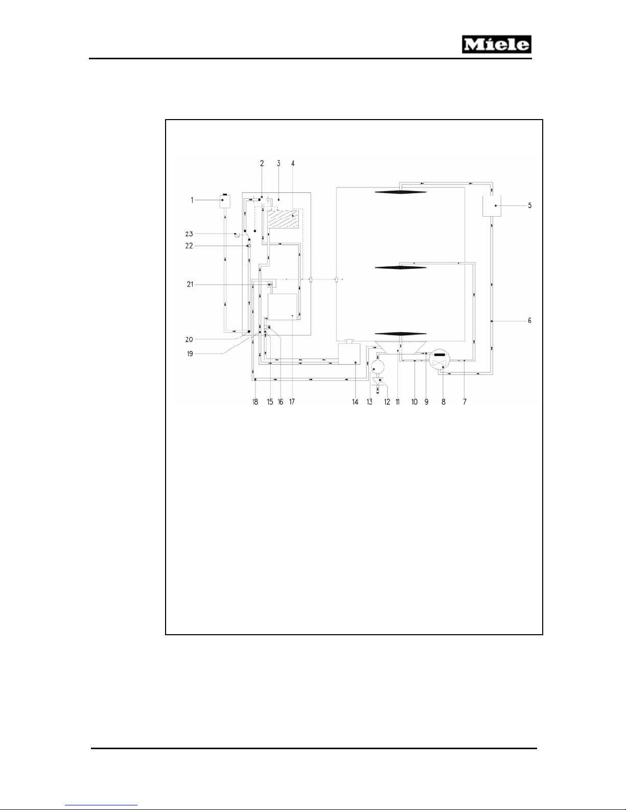
1 Solenoid valve – Water Intake Y2 18 Soft Water Outlet to Sump
2 Ball Valve 19 Water Outlet to Salt Container
3 Water Inlet Mixer 20 Supply to Water Intake Mixer
4 Water Reservoir – Softener Reactivation 21 Non-return Device
5 Turbidity Sensor B3/10 22 Flow Meter B3/4
6 Feed Pipe – Top Spray Arm 23 Solenoid Valve – Wash Water
7 Feed Pipe – Middle Spray Arm Hardness Y5 (EGS)
8 Circulation Pump M6 + Heating R1
9 Feed to Circulation Pump
10 Feed Pipe – Bottom Spray Arm
11 Sump
12 Non-return Valve
13 Drain Pump M8
14 Salt Container
15 Water Intake from Salt Container
16 Solenoid Valve – Reactivation Y38
17 Resin Tank
Figure 4-8: Water Intake and Circulation Paths
Technical Information
41
Page 42
Technical Information
4.3.1 Circulation Pump
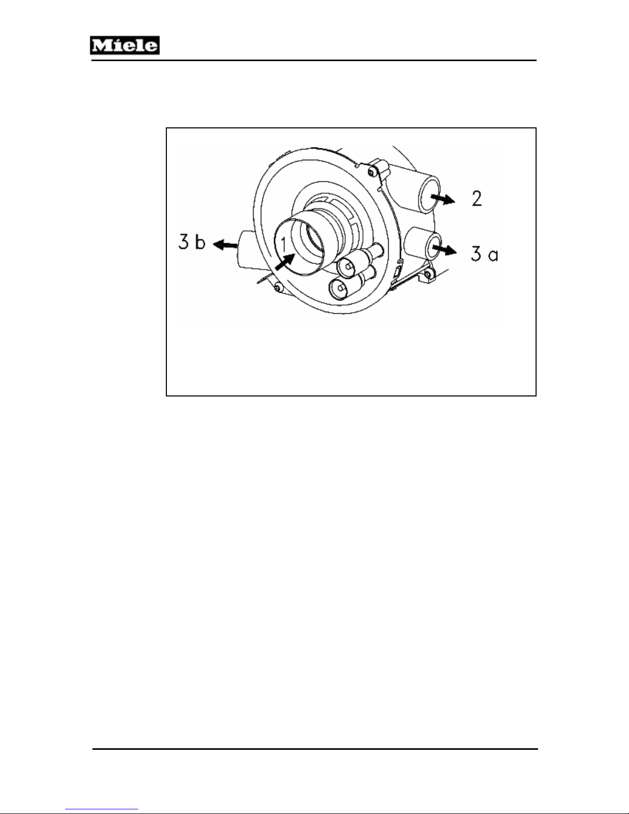
1 Water Intake (suction area)
2 Output to Middle Spray Arm
3a Output to Top Spray Arm
3b Output to Bottom Spray Arm
Figure 4-9: Circulation Pump – Water Paths
Water is passed to the spray arms via the circulation pump. There are two circulation
pump versions depending on model.
Circulation pump with slide shutter: MPEW (approx. 65 W)
With spray arm alternation, the spray arms are only intermittently supplied with
water. This is achieved via a slide shutter, which is moved back and forth as
appropriate to open or close water paths to the different spray arms. For 30 sec. both
the top and bottom spray arms are supplied and during the next 30 sec. the middle
spray arm only. The total water circulation rate is constant and is approx. 34 l/min.
Detergent is only dispensed when the middle spray arm is being supplied with water.
A hall sensor is located between the pump housing and the motor to measure the
pump speed. Depending on the measured value, the quantity of additional water
required, if any, can be established.
G1000 / G2000 Dishwashers
42
Page 43

G1000 / G2000 Dishwashers
Circulation pump without slide shutter: MPEH (approx. 85 W)
With the circulation pump without the slide shutter, all three spray arms are supplied
with water at the same time. The total water circulation rate is approx. 68 l/min.
Approx. 15 l/min flow through the top spray arm, approx. 34 l/min through the middle
spray arm and approx. 19 l/min through the bottom spray arm. This pump version
does not have a speed sensor.
Both pumps are equipped with a winding changeover, which increases the torque at
the moment they are switched on (higher starting torque). In this state the main
winding is connected directly, and the auxiliary winding connected indirectly via the
capacitor, to the power supply.
The winding changes are made via a changeover relay on the electronic module. At
every switch-on, the changeover relay and the circulation pump-starting relay are
supplied with power at the same time. The changeover relay switches the windings
with a time delay.
Both circulation pumps have thermal winding protection.
4.3.2 Circulation Pump - Speed Sensor and Load Sensing
G1570 SC VI, G2570 SC VI G2630 SCI, G2670 SCVI, G2830 SCI
The MPEW circulation pump (with slide shutter) is fitted with a speed sensor (Hall
Sensor), which is located between the pump housing and motor. The pump speed
can be measured via the sensor and a ring magnet mounted on the circulation pump
shaft.
The quantity of water taken in at the start of the program is measured via the flow
meter, B3/4. This basic quantity of water wets the load and settles in certain areas
such as on the bottom of cups. The lower the quantity of water that flows back into
the sump, the greater the quantity of dishes in the appliance, as more water has
been required to wet the load. The way the circulation pump is running is used to
register how much water has flowed back to the sump. If sufficient water has
returned, the pump runs evenly. With too little water, the pump speed fluctuates.
Using this feature, additional small quantities of water are taken in until a stable
motor speed is registered.
By monitoring the speed in this way and thus controlling additional water intake
precisely can reduce energy and water consumption. The potential savings are
approx. 15% water and 19% energy.
43
Technical Information
Page 44
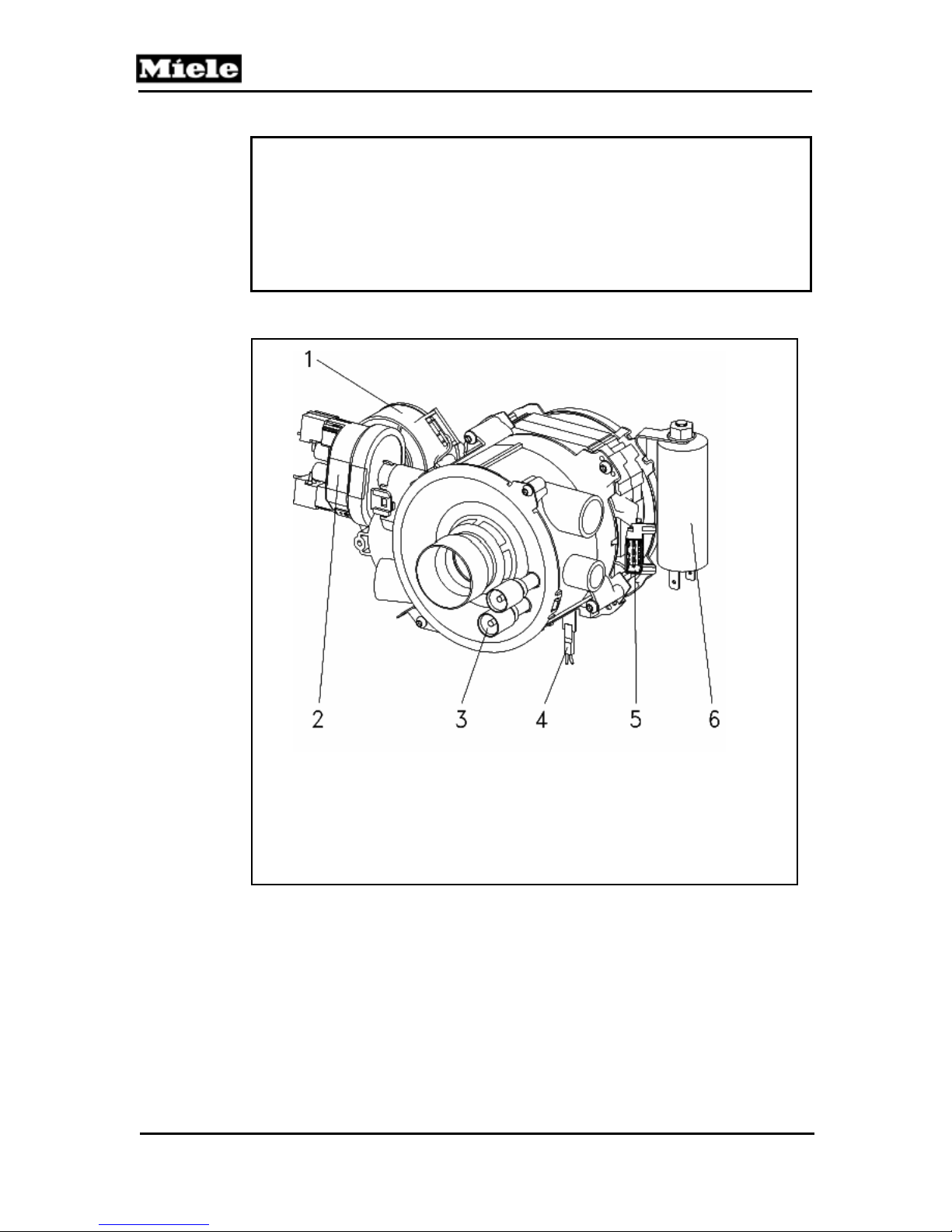
G1000 / G2000 Dishwashers
Technical Information
Note
This system has an additional advantage. Good wash results are also
ensured if the dishwasher load includes items with less than ideal shape
(e.g. cups with deep bases) as the controlled additional water intake will
replace the water that may be trapped in such pieces. This similarly
applies if, e.g., a light plastic bowl should be turned over and filled
inadvertently by the stream of water.
1 Slide Shutter Motor
2 Heater Pressure Switch
3 Heating Elements
4 Speed Sensor (Load Sensor)
5 Motor Connection
6 Capacitor
Figure 4-10: Circulation Pump - Components
44
Page 45

G1000 / G2000 Dishwashers
4.3.3 Heating
A ring heater element in the circulation pump housing heats the water. The heater
element and circulation pump together form one component. This ensures that on
models with spray arm alternation, heating can always be carried out whichever
water path is currently being used.
Integrating the heater element in the pump housing also ensures that it is always
cooled sufficiently thus preventing the baking-on of soil particles or impurities in the
water.
Various safety measures protect the heater element against overheating, such as the
following:
Heater Pressure Switch
NTC Temperature Sensor
Electronic Control
The heater is only activated when the circulation pump has taken in sufficient water.
4.3.4 NTC Temperature Sensor, R30
An NTC sensor is fitted in the sump and monitors water temperatures during
dishwashing.
If the maximum safety temperature of 194° F at the NTC sensor is exceeded, the
program is interrupted (boiling prevention) and fault code F26 is registered, see Fault
code F26, 6.8.15.
If during heating the desired temperature is not reached in the given time, a fault is
registered, see F25, 6.8.12.
If the sensor or its connections are open- or short-circuited, the heating is switched
off. The program then continues to the end without heating or dispensing, see Fault
code F01, (NTC short-circuited), 6.3.12 or Fault code F02, 6.8.12.
45
Technical Information
Page 46
Technical Information
NTC Sensor Resistance Values
Temperature (° F) Resistance (kΩ)
32 35.979
41 28.519
50 22.766
59 18.281
68 14.774
77 11.982
86 9.787
95 8.048
104 6.653
113 5.523
122 4.608
131 3.856
140 3.243
149 2.745
158 2.333
167 1.990
176 1.704
185 1.464
194 1.262
199 1.157
203 1.093
Table 4-1: NTC Sensor Resistance Values
G1000 / G2000 Dishwashers
46
Page 47
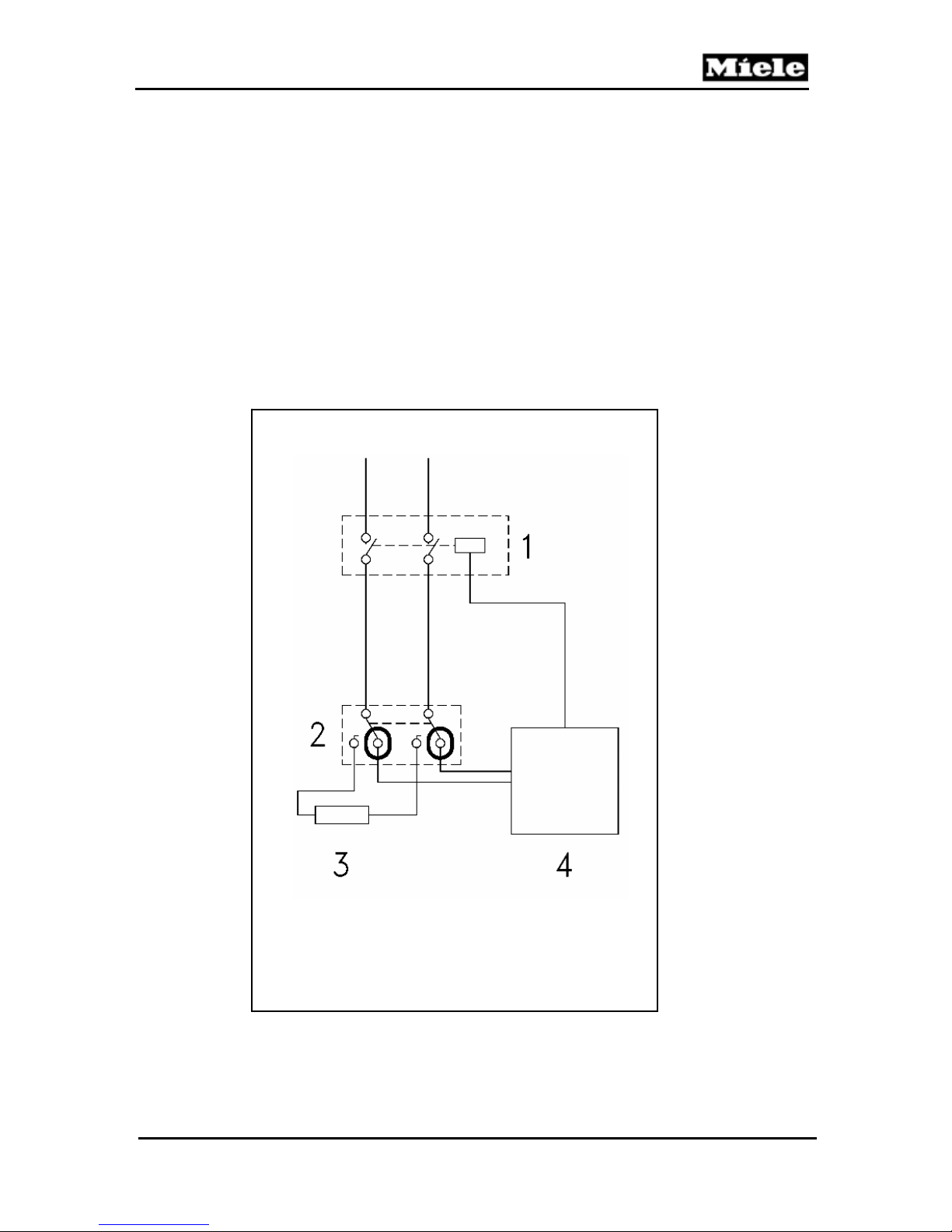
G1000 / G2000 Dishwashers
4.3.5 Heater Pressure Switch, B1/13
The heater pressure switch B1/13 is located directly on the circulation pump and
registers the water pressure when the pump is in operation.
Using the pressure switch contacts, the heating is controlled via 2 poles. The heating
is switched via a heating relay located before the pressure switch contacts in the
circuit. Heating activation occurs during the wash and final rinse cycles.
If the circulation pump and heating relay are activated and the heater pressure
switch reset contact is open, the control registers a water intake fault, see Fault code
F14, 6.8.15.
1 Relay – Heating
2 Heater Pressure Switch
3 Heating Element
4 Electronic Module
Figure 4-11: Heater Pressure Switch Circuit
Technical Information
47
Page 48
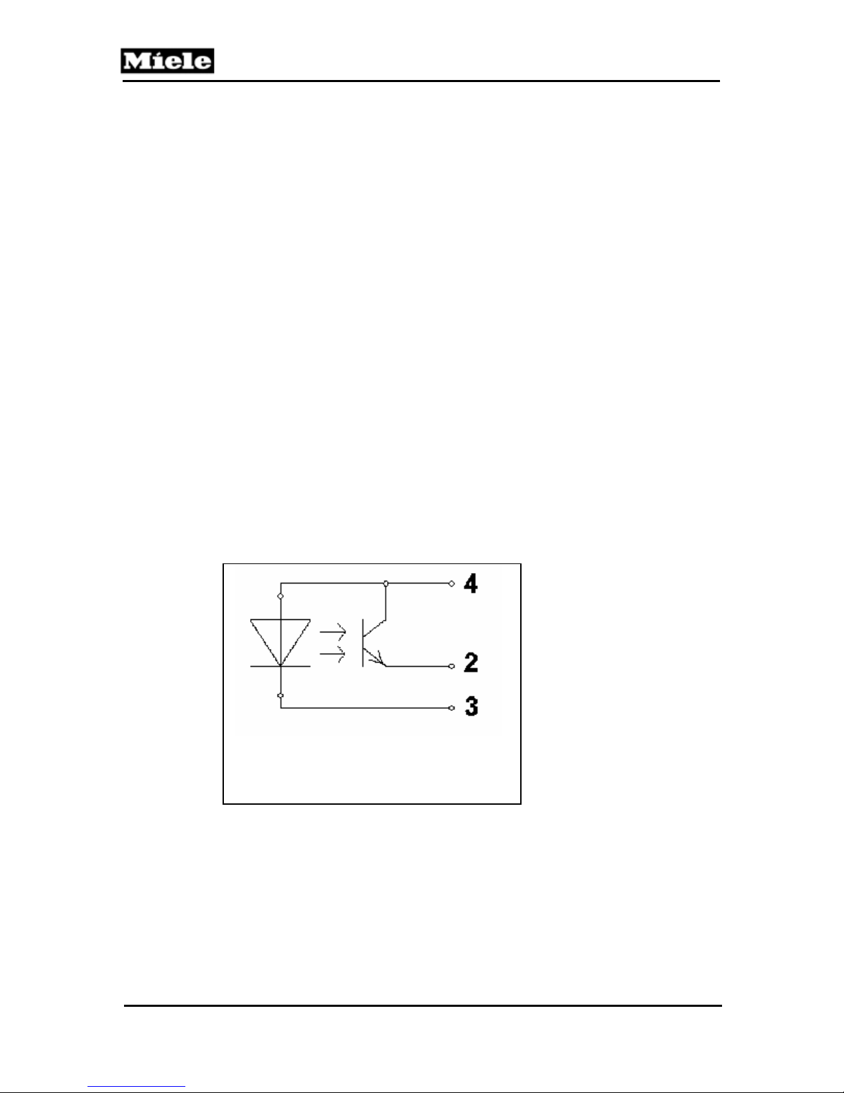
G1000 / G2000 Dishwashers
Technical Information
4.3.6 Turbidity Sensor (ECO Sensor III, Auto-sensor), B3/10
Dishwashers from the G 1000/G 2000 generation are provided with one of two
turbidity sensors, depending on model:
The ECO sensor III measures the turbidity of the water and based on this result, the
wash blocks, temperatures and running times of automatic programs are modified. In
addition to this, the Auto-sensor has a microprocessor to evaluate the particle
measurement.
Principle of Operation
Water circulation and the presence of detergent cause bubbles to develop and
measurement technology cannot differentiate between such bubbles and suspended
soil particles. With the ECO sensor a proportion of the suds is directed into a bypass
channel, which is wider at the other end. This causes the flow rate to reduce and
hence the bubbles in the water to rise. The suspended soil particles in the water can
then be more accurately registered in the following measuring process.
A photoelectric barrier switch (IR diode (infrared) opposite a photo transistor) acts as
a turbidity sensor. Depending on the turbidity (Transparency) of the water, a certain
current flows through the phototransistor. This current is measured and processed by
the electronic unit, which then initiates the appropriate action. If the level of turbidity
passes certain thresholds, then depending on the soiling detected, the following
cleaning cycles are modified accordingly with regard to water quantity, program
duration and temperature.
1 Common 5 V
2 IR LED Cathode
3 Light Receiver Output (Emitter
Figure 4-12: Turbidity Sensor Circuit
48
Page 49
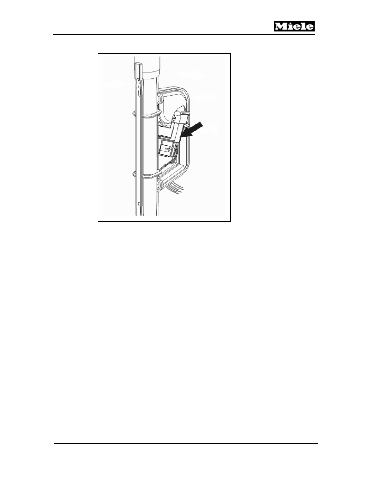
G1000 / G2000 Dishwashers
Figure 4-13: Turbidity Sensor
The sensor is situated in the feed pipe to the top spray arm, as shown in Figure 4-13.
The flow rate is approx. 15 l/min. In order to compensate for residues on the sensor
and ageing of the optical system, the turbidity sensor must be recalibrated regularly.
This process is carried out automatically by the electronic unit and cannot be
modified in any way. Measurements are carried out at different times during the prewash, main wash and interim rinse stages. For this, the top and bottom spray arms
must be supplied with water.
Technical Information
49
Page 50
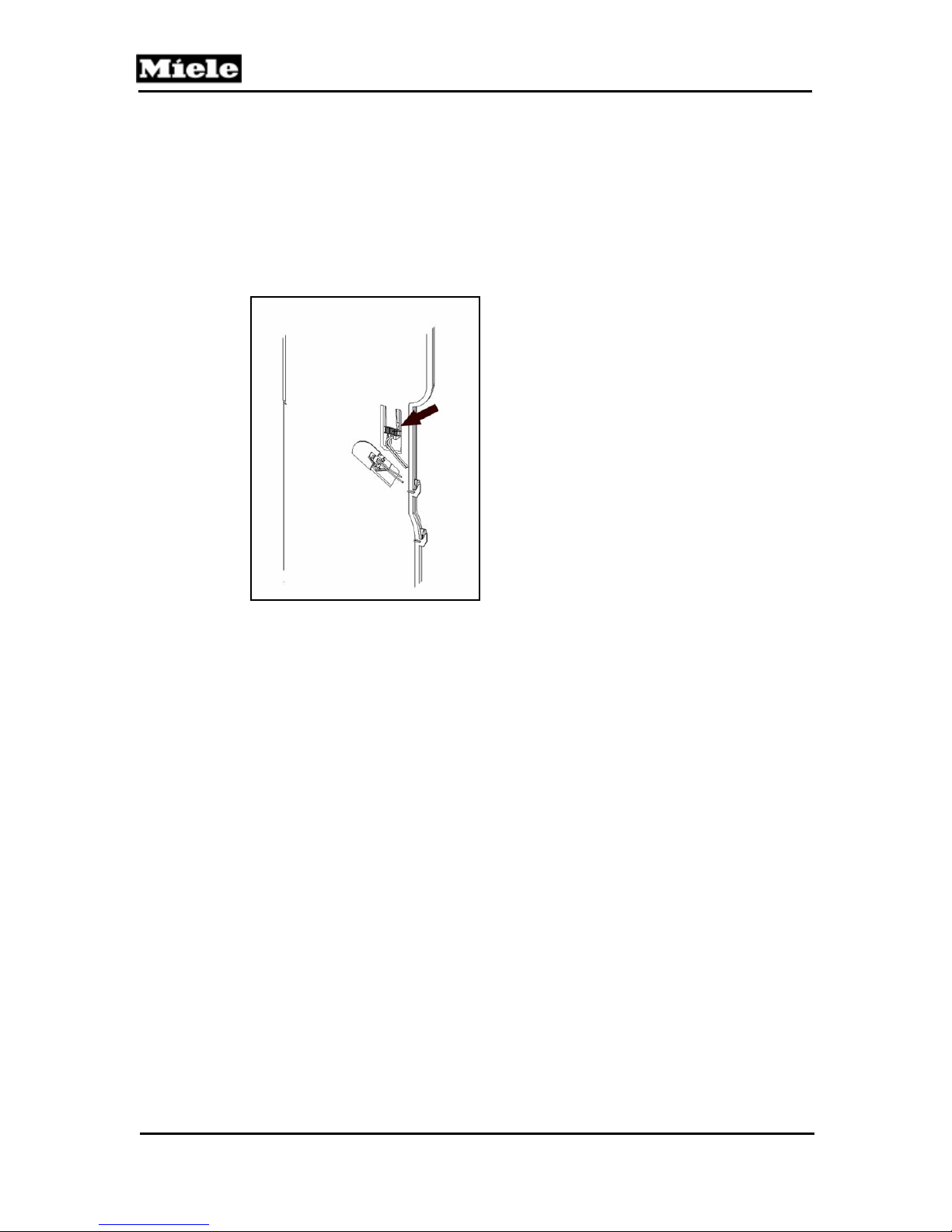
Technical Information
4.3.7 Spray Arm Sensing
Specific model dishwashers are equipped with a spray arm sensing system to alert
the operator that the spray arm is obstructed by a large dish, or utensil etc....
A spray arm sensor(s) is / are fitted on the water intake to monitor the middle and / or
lower spray arm(s) as shown in Figure 4-14. A small magnet is fitted on one end of
the appropriate spray arm.
Figure 4-14: Spray Arm Sensor
The spray arm sensor is only monitored during a program in operation when the
circulation pump is activated.
The time period during which the spray arms are monitored is given by the electronic
control. If a fault is detected, it will be indicated but not saved in the fault memory.
The indication will be cancelled when the fault is remedied.
The minimum spray arm speed is approx. 5 rpm. Therefore approx. 12 sec. after the
start of the monitoring time, the next pulse should be registered.
The maximum spray arm speed is approx. 50rpm. Therefore after the start of the
monitoring time, the next pulse can only be registered at the earliest approx. 1.2 sec.
later.
If a fault is indicated, the indication will remain active even after the door has been
opened. To cancel the fault indication, the door must be closed again.
G1000 / G2000 Dishwashers
50
Page 51
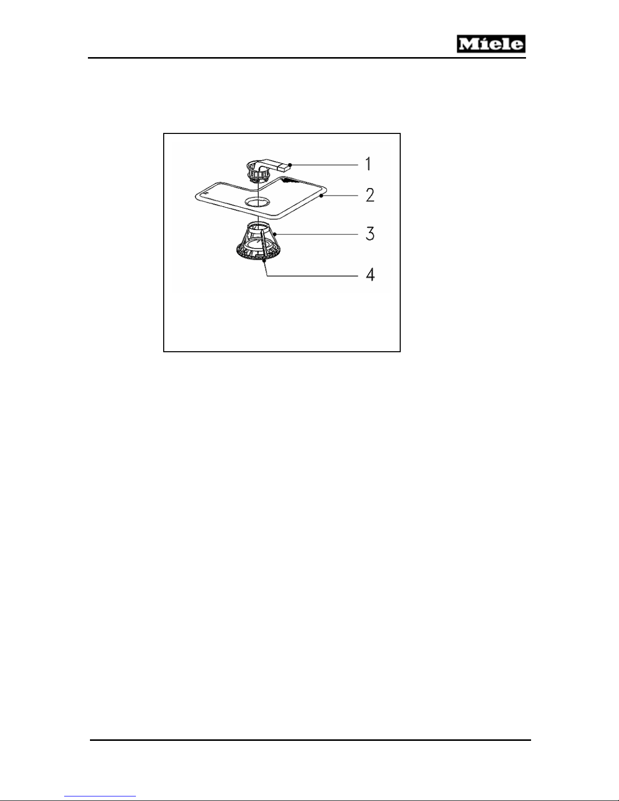
G1000 / G2000 Dishwashers
4.3.8 Filter Combination with Micro Fine Filter
1 Crown Coarse Filter
2 Large Surface Area Fine Filter
3 Micro Fine Filter
4 Filter Cap
Figure 4-15: Filter Combination in Sump
The circulation pump M6 pumps the wash water from the sump via the filter
combination to the spray arms. The circulating wash water is filtered via 2 parallel
paths. A proportion of the water flows through the central opening of the crown
coarse filter and then passes through the conical micro fine filter; see Figure 4-15,
Item 3. The remainder passes directly through the large surface area fine filter; see
Figure 4-15, Item 2, which has a small additional hole to provide a vent for the
circulation pump intake area. All water is then mixed together again in the sump
where it is taken in by the circulation pump and the circuit is repeated. In this way
some of the water passing through the filter system always passes through the micro
fine filter so the proportion of soil particles in the suds is continually being reduced.
Soil that is retained by the micro fine filter either collects there or falls onto the filter
cap where it will eventually be removed by the drain pump.
The crown coarse filter, see Figure 4-15, Item 1, is attached to the filter combination
handle. If dispensed powder detergent should fall into the micro fine filter, it remains
on the filter cap where it can dissolve, instead of collecting in the drain outlet. Foreign
bodies, which pass the crown coarse filter to the micro fine filter collect on the filter
cap and so cannot block the drain outlet.
Technical Information
51
Page 52
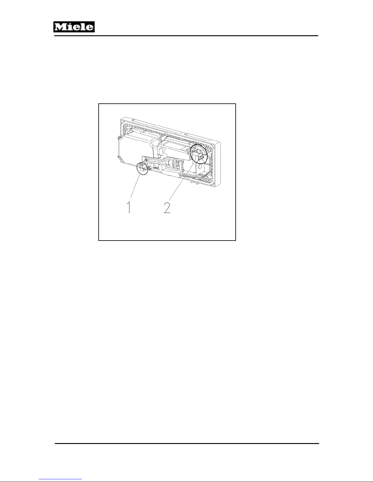
Technical Information
4.4 Dispensing
4.4.1 Combination Dispenser
1 Reed Switch
2 Solenoid
Figure 4-16: Combination Dispenser
The dispenser contains a solenoid that is activated via pulses to dispense detergent
and rinse aid. The first pulse opens the detergent dispenser flap. All following pulses
then dispense rinse aid.
During detergent dispensing the solenoid is activated by a brief pulse, and this opens
the detergent dispenser flap.
Rinse aid is dispensed in pulses. Each solenoid impulse dispenses approx. 1 ml
rinse aid into the cabinet interior. 3 solenoid pulses are therefore required to
dispense the normal quantity of rinse aid of 3 ml per wash. Each pulse is applied for
approx. 10 sec. so that there is sufficient time for the rinse aid to flow into the
cabinet. The pause between individual pulses is also approx. 10 sec.
If the rinse aid container is empty, a reed switch is activated and this lights up an
LED in the control panel or display. The rinse aid container has a capacity of 110 ml.
G1000 / G2000 Dishwashers
52
Page 53

G1000 / G2000 Dishwashers
4.5 Drain System
4.5.1 Drain Pump
The drain pump M8 is driven by a synchronous motor and located under the cabinet
on the left next to the sump. It is directly activated by the electronic module. In case
of fault, the drain pump M8 is also activated directly via the overflow float switch
B8/3. The drain pump pumps the suds via the non-return valve and the drain hose to
the on-site drain.
During drainage the drain pump M8 extracts water from below the microfine filter.
This reverses the direction of flow through the microfine filter that normally exists
during the cleaning and rinse cycles. Soil particles that have been trapped in the filter
during dishwashing are then flushed out with the drain water.
Pumping limits:
Max. 13’ hose length
Max. 3’ 3” head height
Most faults will cause the program in operation to be interrupted and the drain pump
to start.
If the WaterProof System has been activated, Fault code F70, 6.8.15, the drain pump
continues to operate even after the appliance has been switched off. In this case, the
pump is only switched off when the power source is disconnected.
Technical Information
53
Page 54
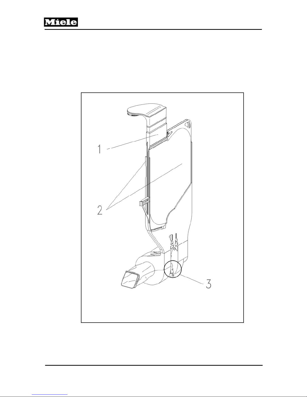
G1000 / G2000 Dishwashers
Technical Information
4.6 Drying
Depending on model and production time frame, the G1xxx/G2xxx series
dishwashers are outlined below:
4.6.1 Circulation Turbothermic Drying (active): UTT Version 1
1 Inner Fan Channel
2 Outer Fan Channel
3 Fan
Figure 4-17: Drying System UTT Version 1
54
Page 55

G1000 / G2000 Dishwashers
Circulation Turbothermic drying (UTT) operates with two separate air paths:
Condensing Circuit
To get dishes dry, moisture has to be removed from the dishwasher cabinet. The
moist, warm air in the cabinet is gradually cooled. Cold air can hold less moisture
than warm air, and thus, in this cooling process condensation drops form, which
settle in the coldest areas of this circuit. To remove moisture from the air in the
dishwasher cabinet, the air is sucked in above the cutlery tray (right front) and
channeled into a condensing pocket. This condensing pocket is located in the right
outer wall of the dishwasher with cool ambient air circulating around it, which results
in a faster cooling of the moist, warm air in the dishwasher cabinet. To enhance the
heat dissipation, the side panels are made of a thin (0.1 mm) stainless steel foil. The
de-humidified air and the condensation go back into the dishwasher cabinet via the
round opening at the side. The condensation (maximum ½ water glass) collects in
the sump, and the air continues circulating. At the end of the program, the
condensation is drained off.
Cooling Circuit With Ambient Air
To cool off the warm air in the cabinet, cold or cooler air is needed. To this end,
ambient air is sucked in at the front bottom area and channeled past the sides of the
condenser. These are the areas between condenser and the outside wall of the
dishwasher, and between the condenser and the dishwasher cabinet wall. The air is
then passed back into the room at the top rear wall. The effect is an efficient heat
transfer, turning the warm air into cooler air and removing more and more moisture
from the air in the cabinet, thereby drying the dishes effectively.
The clear separation of ambient air and dishwasher cabinet air has the following
advantages:
Independent of the type of water connection (cold or hot water) a good drying result
is achieved.
By clearly separating the condensation and cooling circuit, air discharge at the front
panel is eliminated. The inside air remains completely inside the dishwasher cabinet.
Technical Information
55
Page 56
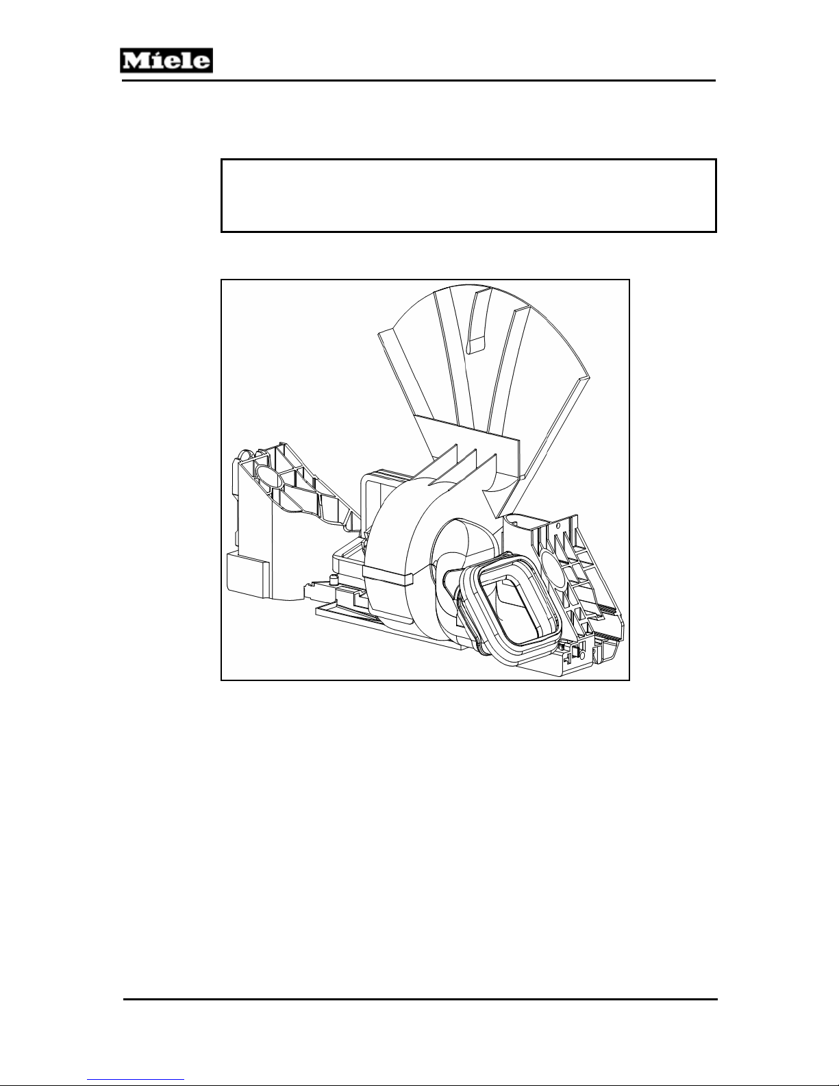
G1000 / G2000 Dishwashers
Technical Information
4.6.2 Circulation Turbothermic Drying (active): UTT Version 2
Note
This system is installed in models Gx04x – Gx47x starting with production
index 34/…
Figure 4-18: Drying System UTT Version 2
The function of both versions of circulation Turbothermic drying is comparable.
However, Version 2 has no condenser pocket. Therefore the dishwashing cabinet is
completely closed – the openings, to which the condenser pocket is attached in
Version 1, are eliminated.
As a result, the entire area of the right side panel is cooled by the fan. The moist,
warm cabinet air settles in the coldest areas of the cooling circuit and condenses on
the cool cabinet inside wall. Moisture is removed from the cabinet, and the dishes dry
through the residual heat. The condensation runs down the cabinet inside wall to the
sump and is pumped off at the end of the program.
56
Page 57

G1000 / G2000 Dishwashers
4.6.3 Fan
Two different fan types are employed for the two different versions of circulation
Turbothermic drying:
Circulation Turbothermic drying (active): UTT Version 1
A split-pole motor (approx. 23 W) drives two impellers. One impeller directs cool air
across the outer surface of the stainless-steel condensation surface foils. The
second impeller transports steam from the cabinet to the condensation surfaces.
Circulation Turbothermic drying (active): UTT Version 2
A split-pole motor (approx. 19 W) drives an impeller, which transports cool air to the
outer surface of the right side panel.
Technical Information
57
Page 58
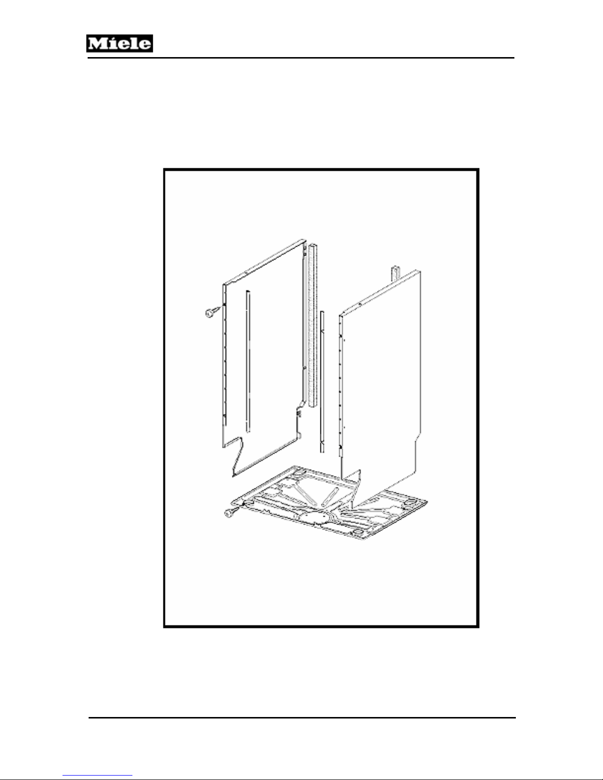
Technical Information
5.0 Service and Maintenance
5.1 Housing
G1000 / G2000 Dishwashers
Figure 5-1: Appliance Housing
58
Page 59
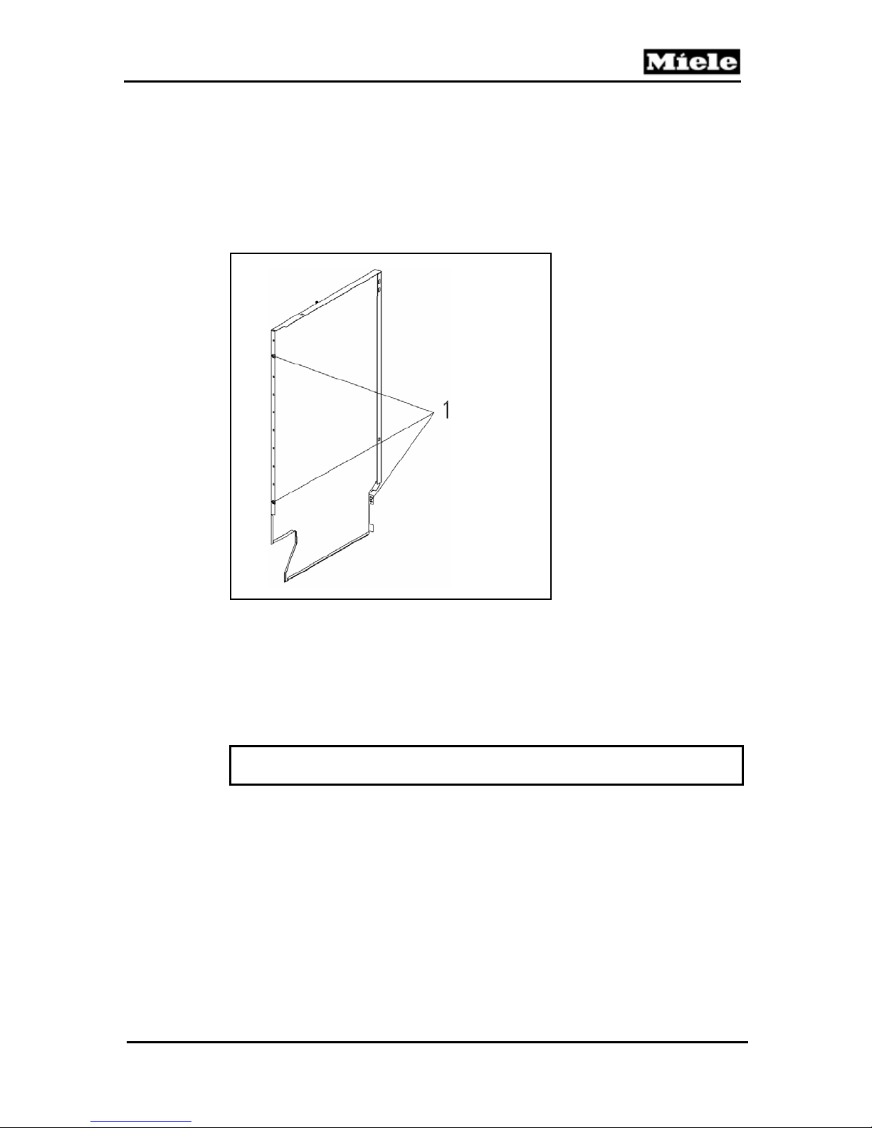
G1000 / G2000 Dishwashers
5.1.1 Side Panel – Removal
1. Refer to Figure 5-2.
2. Remove the three retaining screws - Item 1.
3. Use needle nose pliers to press in the retainer on the corner tabs.
4. Remove the side panel.
Figure 5-2: Side Panel Removal
5.1.2 Drip Pan – Removal
Warning
Before tilting the machine onto its back, the following must be carried out:
1. Open the salt container cap briefly then close it firmly - to empty the water inlet
mixer.
2. Pump water out of the cabinet.
3. Lay the dishwasher on its back.
4. Refer to Figure 5-3.
5. Remove the retaining screws - Item 1.
Technical Information
59
Page 60
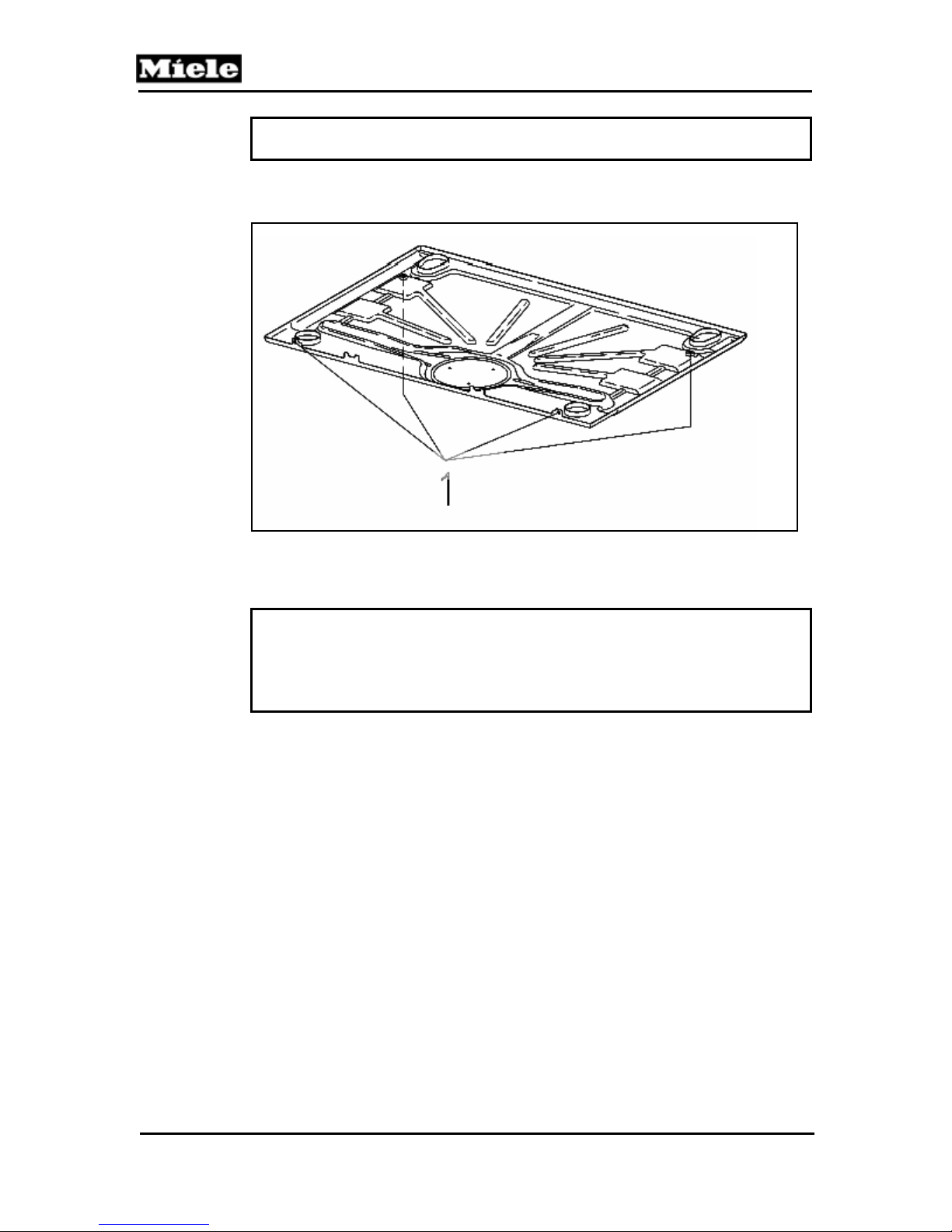
Technical Information
Warning
Ensure that the intake and drain hoses are not crushed.
Figure 5-3: Drip Pan Removal
Important
To ensure a proper ground connection, the screws with the serrated
surface under their heads MUST be used to secure the drip pan to the
connection strip.
G1000 / G2000 Dishwashers
FRONT
60
Page 61
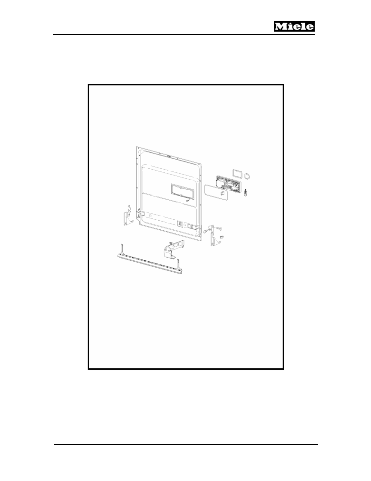
G1000 / G2000 Dishwashers
5.2 Door
Technical Information
Figure 5-4: Door Panel
5.2.1 Front Panel (GDU / Custom) – Removal
61
Page 62
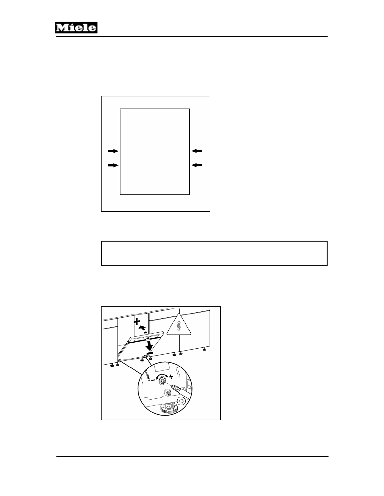
G1000 / G2000 Dishwashers
Technical Information
1. Remove the screw caps from the side of the door (2 each side).
2. Support the panel while loosening the 4 screws, Figure 5-5.
3. Lift / remove the panel from the appliance.
Figure 5-5: Integrated Door Panel Screw Locations
Important
Loosen the screws – Do NOT completely remove them.
During reassembly do NOT over tighten the screws.
5.2.2 Door Tension – Adjustment
Figure 5-6: Door Tension Adjustment
62
Page 63
G1000 / G2000 Dishwashers
Note
The front door must be completely assembled before performing the door
adjustment. This includes the installation of the GDU panel or custom
panel.
1. Remove the Toe Kick.
2. Refer to Figure 5-6.
3. Open the door about halfway.
4. Use a Torx T20 driver to adjust the tension.
Important
The door tension should be adjusted so the door stays where it is placed.
It should NOT spring open; or require a loaded basket be kept in place to
prevent it from closing.
Technical Information
63
Page 64
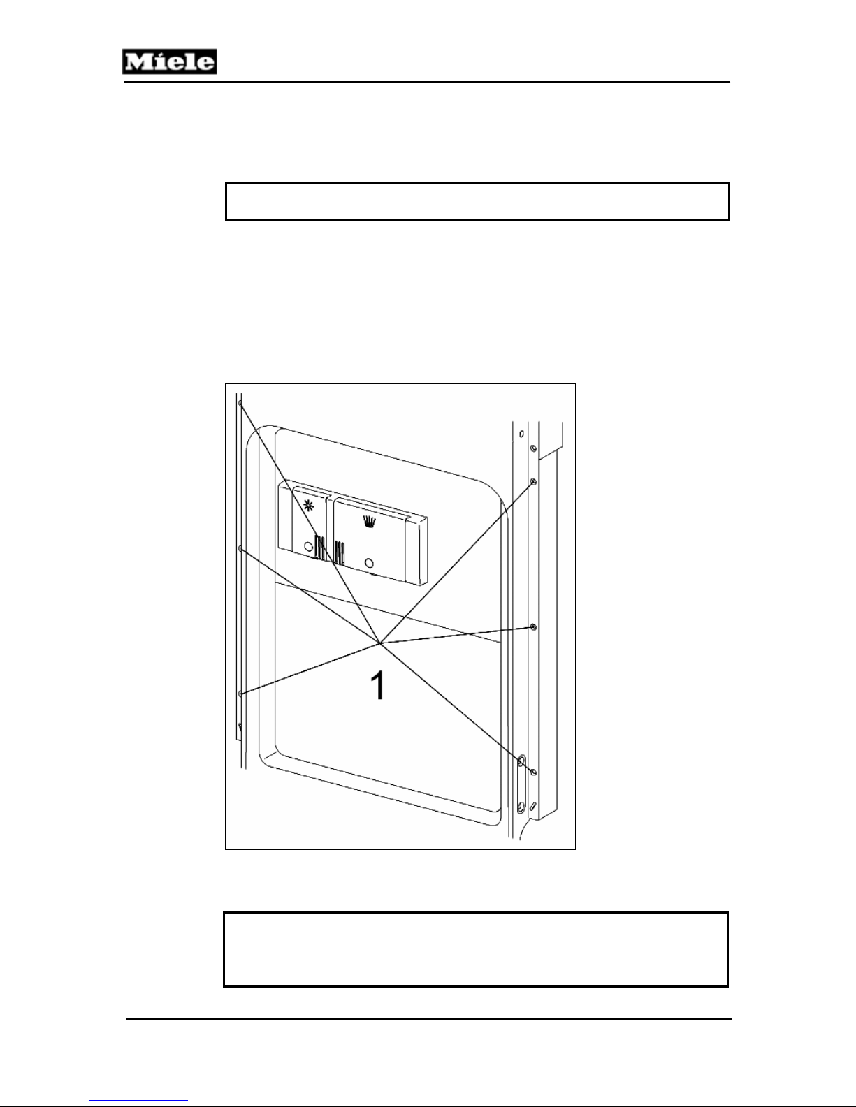
G1000 / G2000 Dishwashers
Technical Information
5.2.3 Outer Door Panel – Removal
Caution
Support the outer panel while removing the retaining screws.
1. Remove the front panel (5.2.1).
2. Refer to Figure 5-7.
3. Open the door and remove the countersunk screws (Item 1) from the perimeter
of the door.
4. Close the door and remove the door outer panel.
Figure 5-7: Outer Door Panel Removal
Note (Integrated Models)
When fitting the door outer panel, make sure that the cutouts in the door
outer panel are correctly located in the holding plate.
64
Page 65
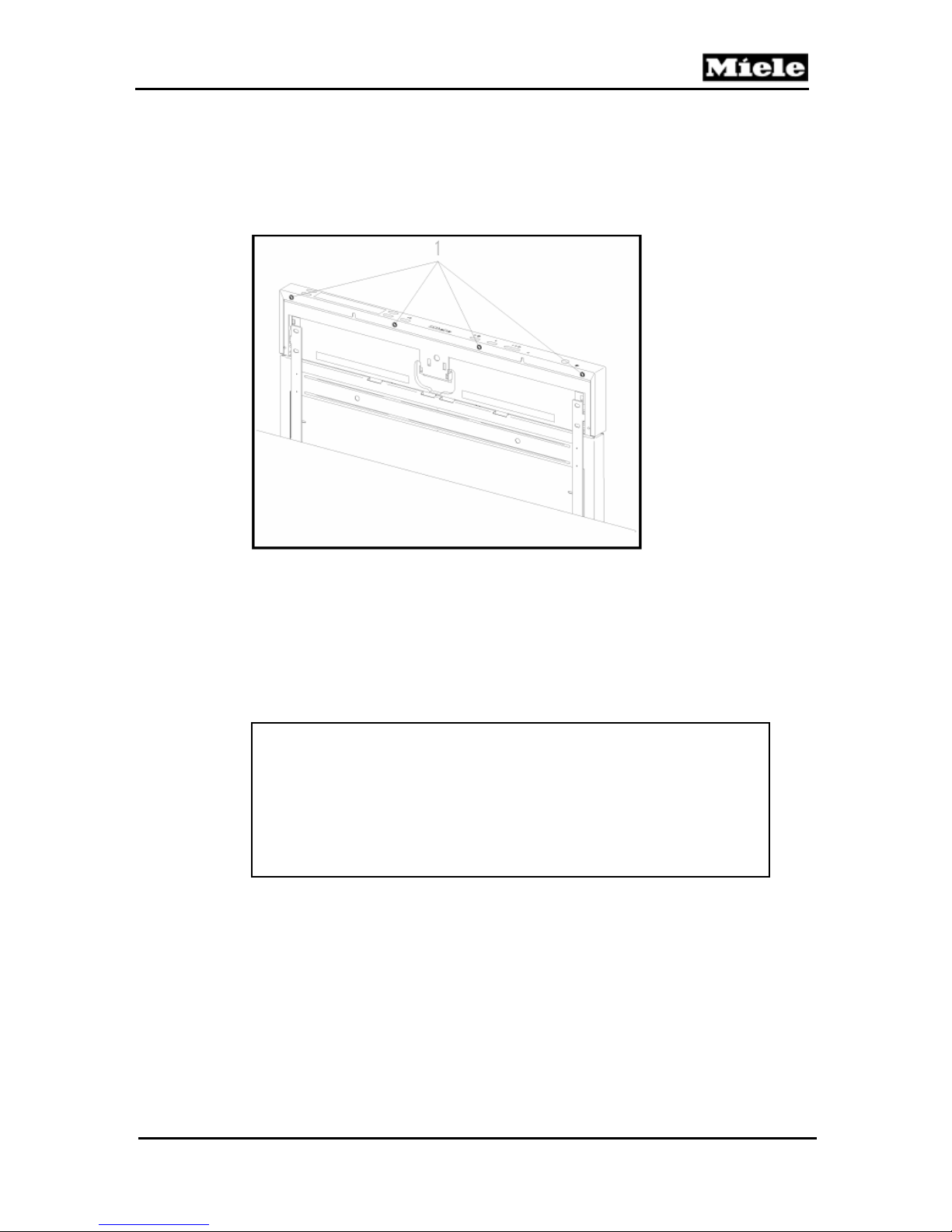
G1000 / G2000 Dishwashers
5.2.4 Fascia Panel Removal
Technical Information
Figure 5-8: Door Fascia Panel
1. Remove the retaining screws, Fig. 5-8, Item 1.
2. Slide the fascia panel upwards.
5.2.5 Door Hinge - Removal
Note
When refitting, care must be taken with the following:
• The fascia must be fitted before the switch buttons are
refitted.
• To secure the fascia panel, only short screws
(countersunk self-tapping 3.9 x 14) may be used as
otherwise the electronic unit holder could be damaged.
65
Page 66
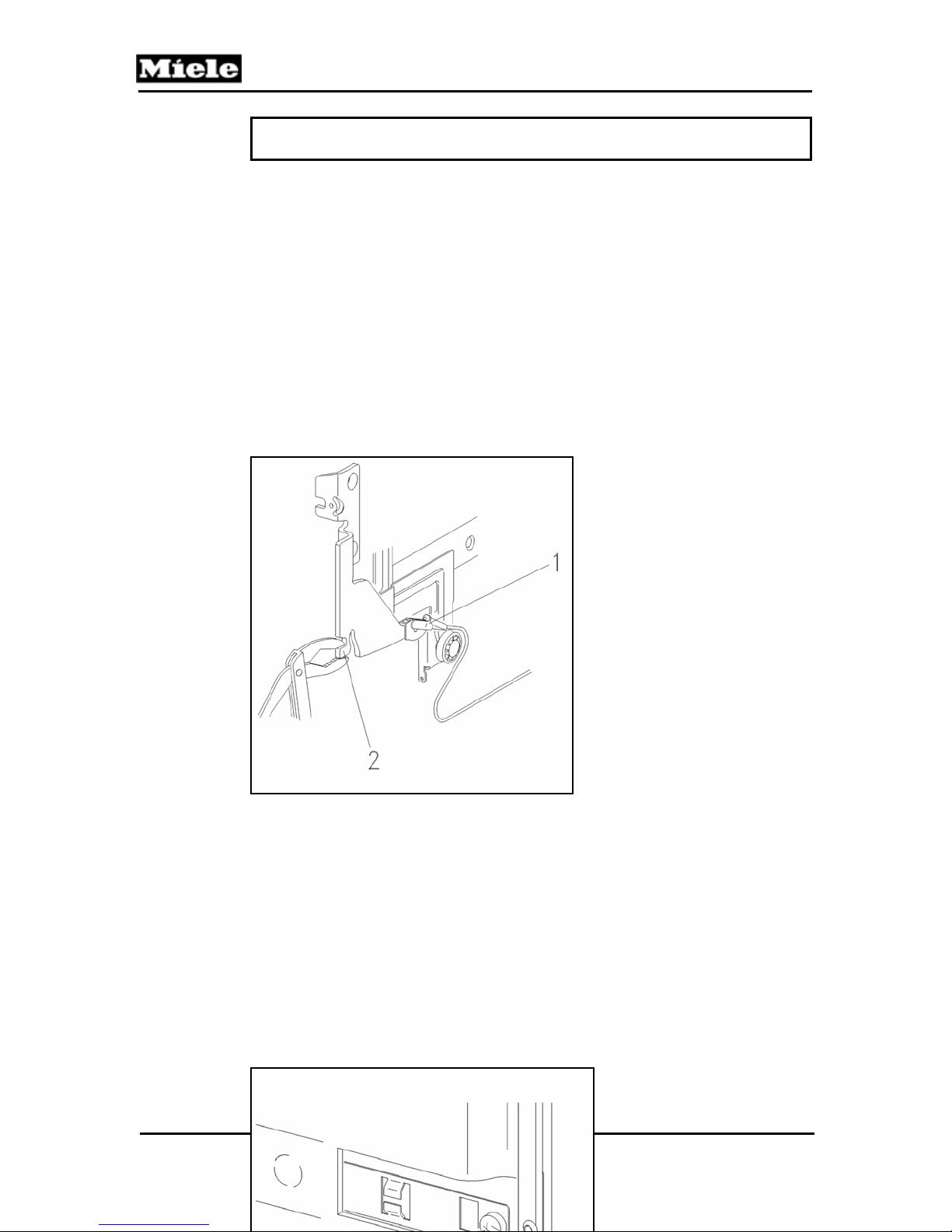
Technical Information
Note
Door hinges must be replaced in pairs.
1. Remove the outer door panel (5.2.3).
2. Remove the right and left side panels (5.1.1).
3. Close the door.
4. Relax the tension in the ropes of the tension springs.
5. Refer to Figure 5-9.
6. Disconnect the ropes from the tension springs - Item 1 (Use special tool Miele
Mat. # 05054690 to decrease tension to spring).
7. Open the hinge by bending it upward - Item 2.
8. Disconnect the ground cable.
9. Remove the cable.
10. Unhinge the door and place it onto pad.
11. Remove the seal at door.
Figure 5-9: Opening the Hinge Bracket
G1000 / G2000 Dishwashers
66
Page 67
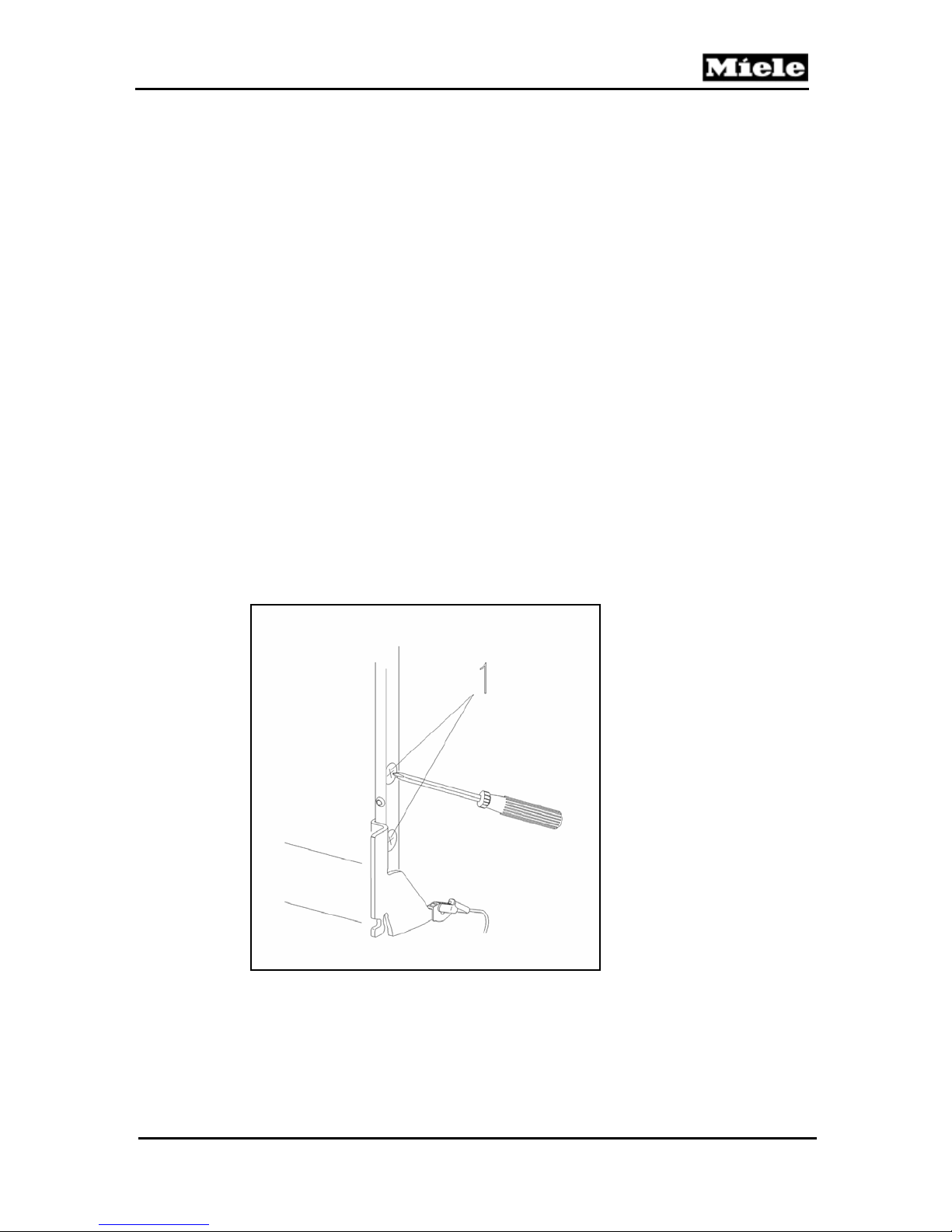
G1000 / G2000 Dishwashers
Figure 5-10: Front Hinge Retaining Screw
12. Remove the front door hinge retaining screws (Figure 5-10 - Item 1).
13. Remove the side door hinge retaining screws (Figure 5-11 - Item 1).
Figure 5-11: Side Hinge Retaining Screw
5.2.6 Combination Dispenser Unit - Removal
Technical Information
67
Page 68
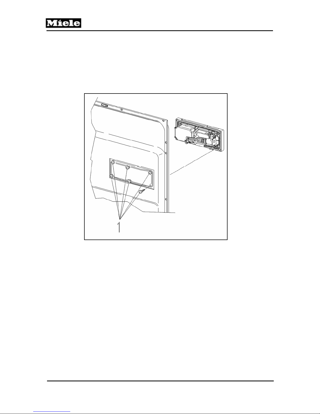
Technical Information
1. Remove the outer door panel (5.2.3).
2. Disconnect the connections from the dispenser
3. Remove the retaining screws (Figure 5-12, Item 1).
4. Release the retaining clips (2 on top & 1 on bottom) and press out the dispenser
unit.
5. Ensure the new dispenser functions correctly using the service mode.
Figure 5-12: Dispenser Removal
5.2.7 Cable Holder - Removal
1. Remove the outer door panel (5.2.3).
2. Open the cable holder cover with a screwdriver.
3. Disconnect the ground connection to the door.
4. Loosen the clip.
5. Remove the cable holder.
5.2.8 Bottom Door Seal - Removal
G1000 / G2000 Dishwashers
68
Page 69
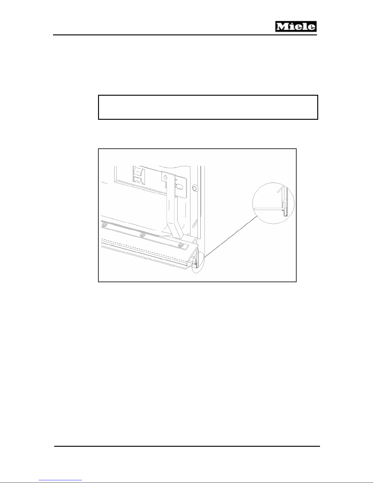
G1000 / G2000 Dishwashers
1. Remove the cable holder (5.2.7).
2. Remove the door seal.
Note
When fitting the door seal, make sure that the seal holder is fitted back in
the double U shape of the door inner panel.
Figure 5-13: Lower door seal holder
5.2.9 Locking Plate - Adjustment
Technical Information
69
Page 70
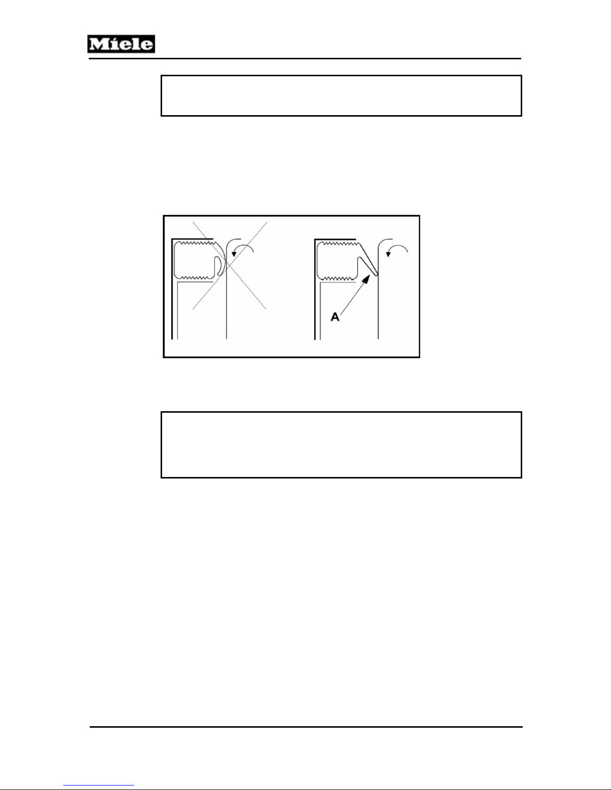
A
G1000 / G2000 Dishwashers
Technical Information
Note
Ensure the appliance is perfectly level.
1. Open the door.
2. Loosen the flat round screw.
3. Adjust the locking plate – as necessary.
4. Tighten the screw.
Figure 5-14: Door Seal with Door
Note
djust the locking plate such that the door seal is not excessively crushed
and not under excess pressure when the door is closed (see Figure 5-14,
Item A). The locking plate can be adjusted by 1 mm in either direction.
5.2.10 Door Lock – Removal (Integrate Models)
70
Page 71
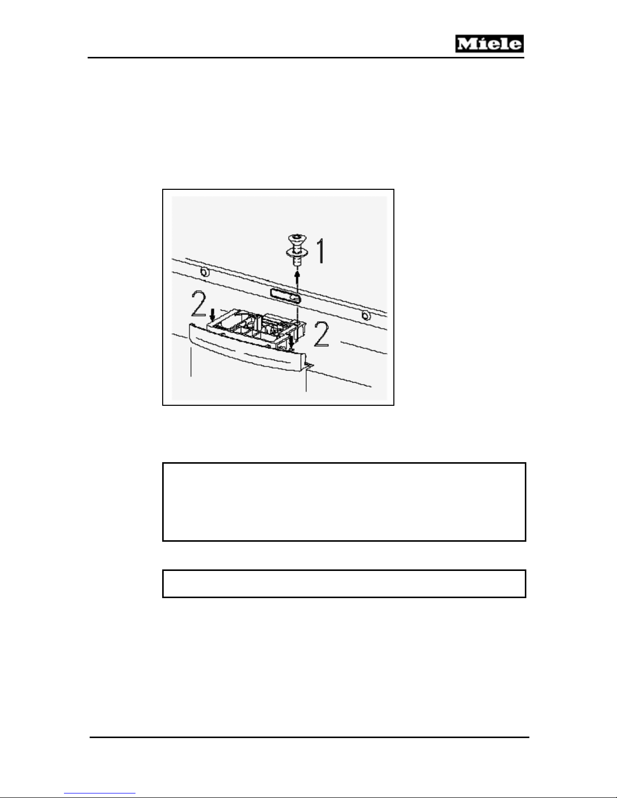
G1000 / G2000 Dishwashers
1. Remove the outer door panel (5.2.3).
2. Remove the retaining screw, Figure 5-15 - Item 1.
3. Press down the retaining lugs with a screwdriver, Figure 5-15 - Item 2.
4. Pull the door lock slightly to the front.
5. Remove the side screws from the inner door panel.
6. Remove the holding plate.
7. Remove the door lock from the holding plate.
8. Disconnect all plugs.
Figure 5-15: Door Lock Removal
Note
During reassembly ensure that the protective shield:
- Is NOT pushed to one side or torn.
- The tab is positioned between the holding plate and door lock.
- Is positioned under the plug area.
Important
Ensure the sealing ring under the door lock retaining screw is reinstalled.
5.2.11 Door Switch – Replacement (Integrated models)
1. Remove the door lock (5.2.10).
Technical Information
71
Page 72
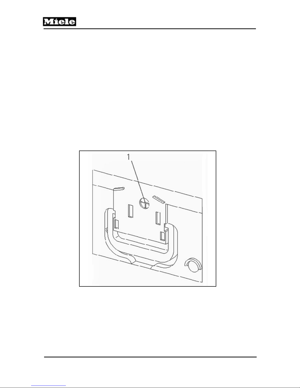
G1000 / G2000 Dishwashers
Technical Information
2. Bend the retaining lug on the switch to the side.
3. Replace the switch.
5.2.12 Fully Integrated (VI) Lock with Door Contact Switch Removal
1. Door outer panel removal (5.2.3).
2. Fascia panel removal (5.2.4).
3. Remove the screws from the sides of the door inner panel.
4. Remove the lock retaining screw.
5. Remove the holder with electronic unit.
6. Remove the lock with door contact switch.
7. Disconnect the door contact switch plug connections.
5.2.13 Door lock emergency release – Activate (Fully Integrated)
1. Remove outer door panel (5.2.3).
Figure 5-16: Door lock emergency release.
2. To return the locking latch into the right position, push on the emergency release
with a screwdriver, see figure 5-16, Pos.1
.
72
Page 73
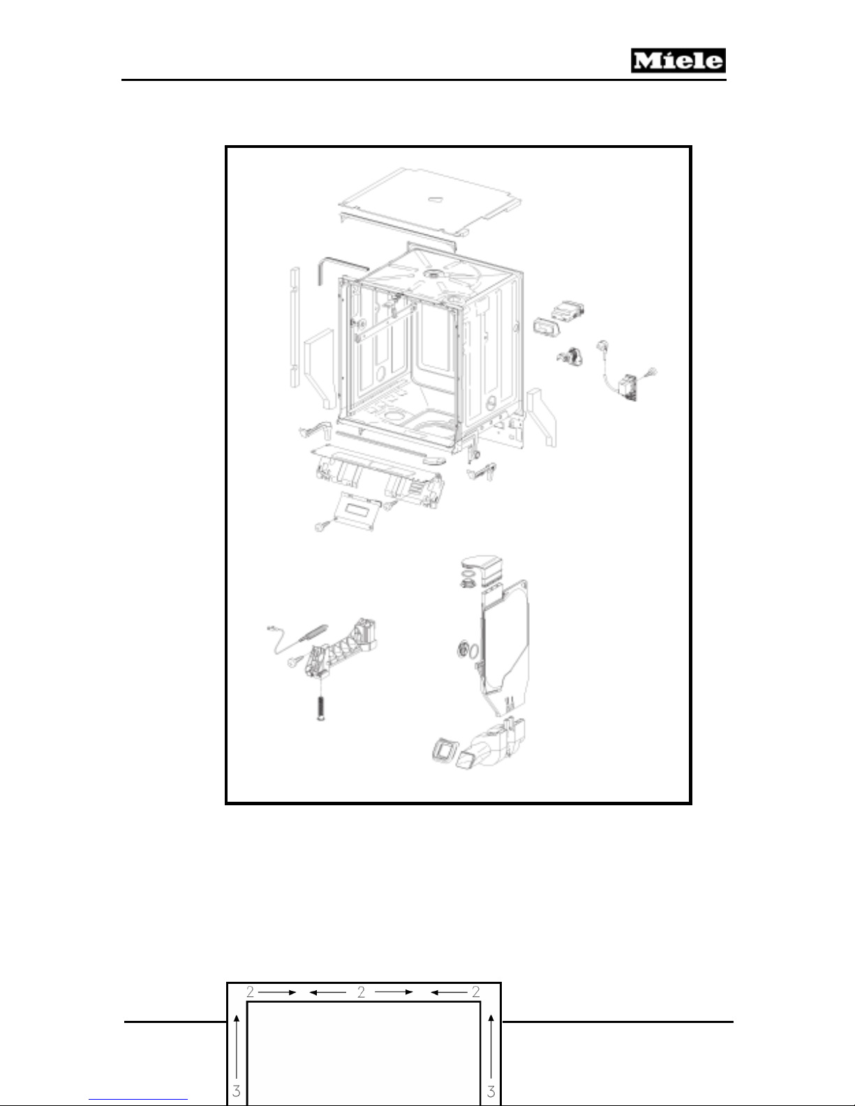
G1000 / G2000 Dishwashers
5.3 Inner Cabinet
5.3.1 Door Seal - Replacement
Technical Information
73
Page 74

Technical Information
Figure 5-17: Door Seal Installation
1. Open the door.
2. Remove the old seal.
3. Clean the groove around the cabinet.
Note
Coating the seal with water may simplify fitting,
4. Refer to Figure 5-17.
5. Press the new seal in the groove, starting at corners (positions 1).
6. Press the middle of seal (positions 2) into the groove under the locking plate,
while pressing the seal into the corners.
7. Press the remaining part of the seal into the groove working upwards in the
direction of the arrows (positions 3).
Note
Coating the seal with water may simplify fitting,
5.3.2 Toe Kick (Plinth Removal)
G1000 / G2000 Dishwashers
74
Page 75
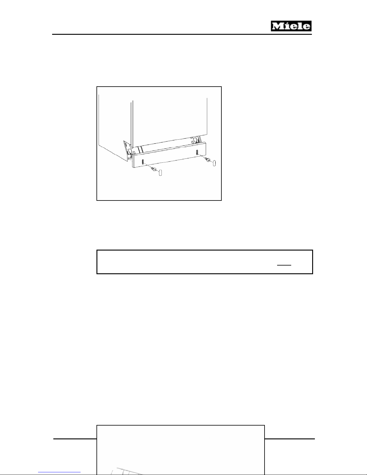
G1000 / G2000 Dishwashers
1. Refer to Figure 5-1, as necessary.
2. Remove the screw caps.
3. Remove the retaining screws
Figure 5-18: Toe Kick (Plinth) Removal
5.3.3 Cover Plate - Removal
Warning
Due to the close proximity of the terminal block the appliance
unplugged before removing the cover plate.
1. Remove the toe kick (plinth) (5.3.2).
2. Remove the two cover retaining screws, Figure 5-19.
3. Remove the cover plate.
Technical Information
must be
75
Page 76
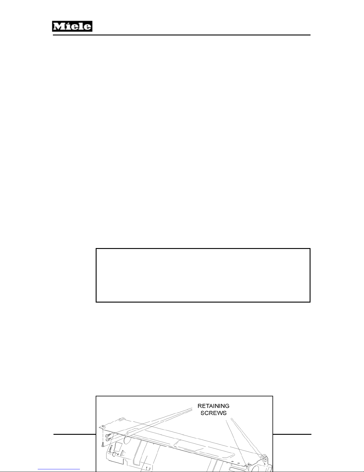
G1000 / G2000 Dishwashers
Technical Information
Figure 5-19: Cover Plate Removal
5.3.4 Connecting Strip (Lower Support) – Removal
Important
The connecting strip should only be removed with the appliance
uninstalled, and positioned on its back.
Do not attempt to remove the connecting strip with the appliance installed
in an upright position.
1. Remove the toe kick (plinth) (5.3.2).
2. Remove the cover plate (5.3.3).
3. Remove the drip pan (5.1.2)
4. Remove the retaining screws, Figure 5-20.
5. Unscrew the machine feet slightly.
6. Carefully remove the connecting strip. See note below.
76
Page 77
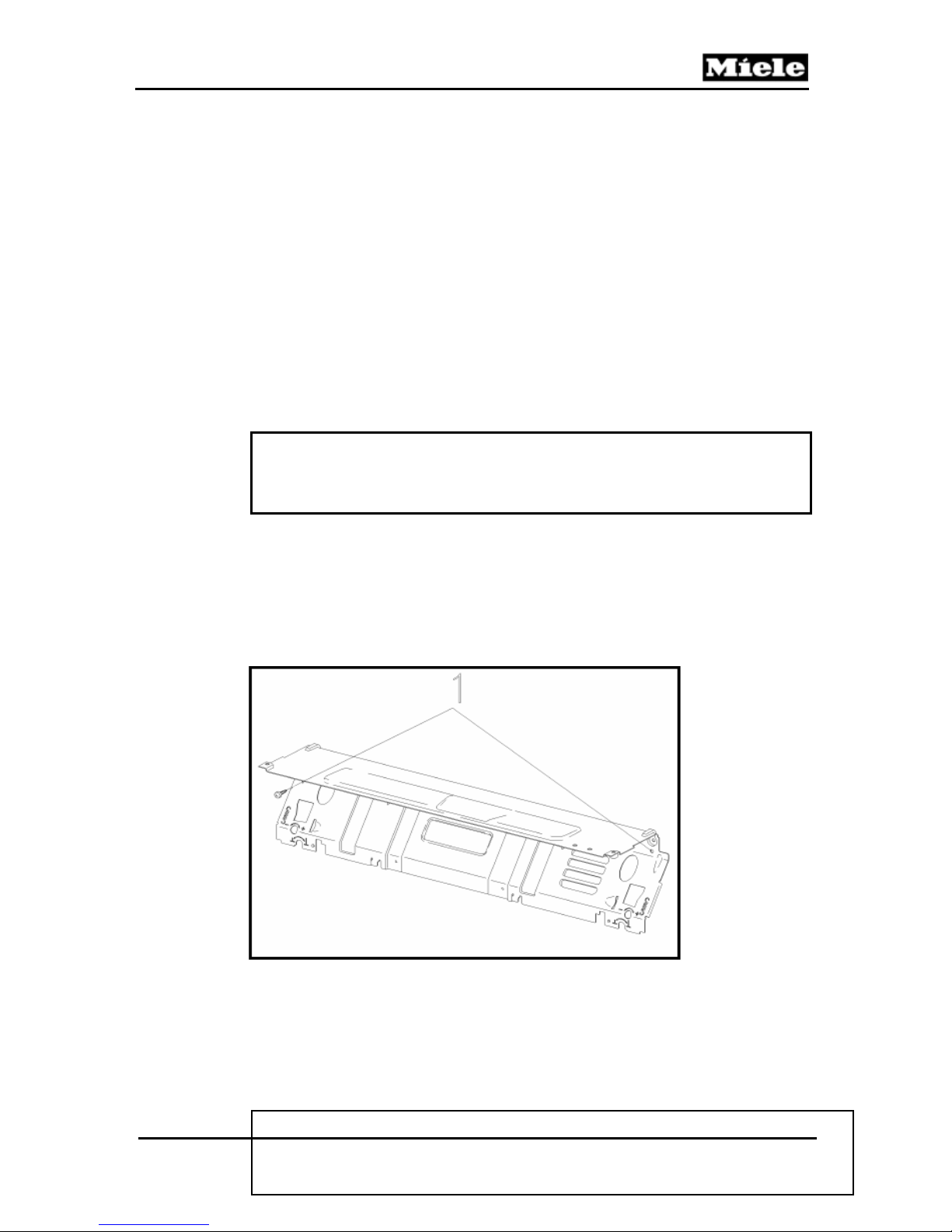
G1000 / G2000 Dishwashers
Figure 5-20: Connecting Strip Removal
Note
Use care when removing the connecting strip as the electrical connector
to the waterproof inlet valves are held in place by retainers mounted on
the inside of the connecting strip.
Technical Information
5.3.5 Multi-Plinth Removal (Door Tension Spring Housing)
1. Side panel removal (5.1.1).
2. Connecting strip removal (5.3.4).
Figure 5-21: Connecting Strip
3. Remove the connecting strip retaining screws, Fig. 5-21, Item 1.
4. Release the cord from the spring.
5. Pull out the multi-plinth from the guide integrated in the rear panel.
Note
Take care removing the left plinth. The electrical connector to the waterproof
inlet valves is held in place. To remove, release retaining clips.
77
Page 78

Technical Information
5.3.6 Steam Condenser Removal
1. Remove the right side panel; see Side panel removal (5.1.1).
2. Remove the cutlery tray (if present).
3. Unscrew the splash protection cap (connection piece to air duct) in the cabinet.
4. Remove the vent screw.
5. Remove the bottom basket.
6. Remove the air duct (from the condenser).
7. Release the retaining lugs between the condenser and fan, Fig. 5-22, Item 1.
8. Remove the condenser.
G1000 / G2000 Dishwashers
Note
When refitting, make sure that the retaining lugs between the condenser
and fan engage properly.
5.3.7 Fan Removal
1. Remove the right side panel; see Side panel removal,( 5.1.1).
2. Drip pan removal (5.1.2).
3. Multi-plinth removal (Right side only) ( 5.3.5).
4. Disconnect all plug connections from the fan.
78
Page 79
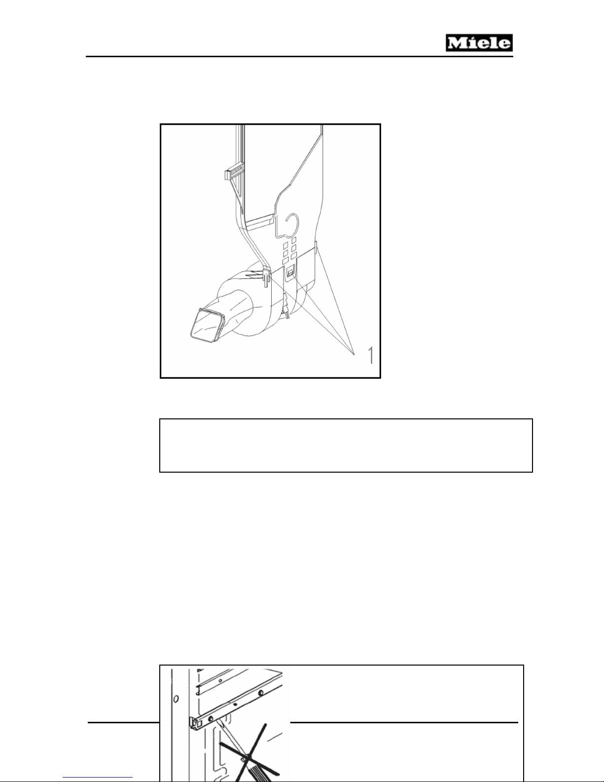
G1000 / G2000 Dishwashers
y
5. Release the retaining legs between the condenser and fan, Fig. 5-22, Item 1.
6. Pull the fan out of its connection to the condenser.
Technical Information
Figure 5-22: Condenser and Fan Assembly
5.3.8 Basket Runners - Removal
Note
When refitting, make sure that the retaining lugs between the condenser
and fan engage properly.
Warning
Do not lever the basket runner off in
the area of the bolts, since this could
79
lead to
permanent damage to the wash
cavit
.
Page 80
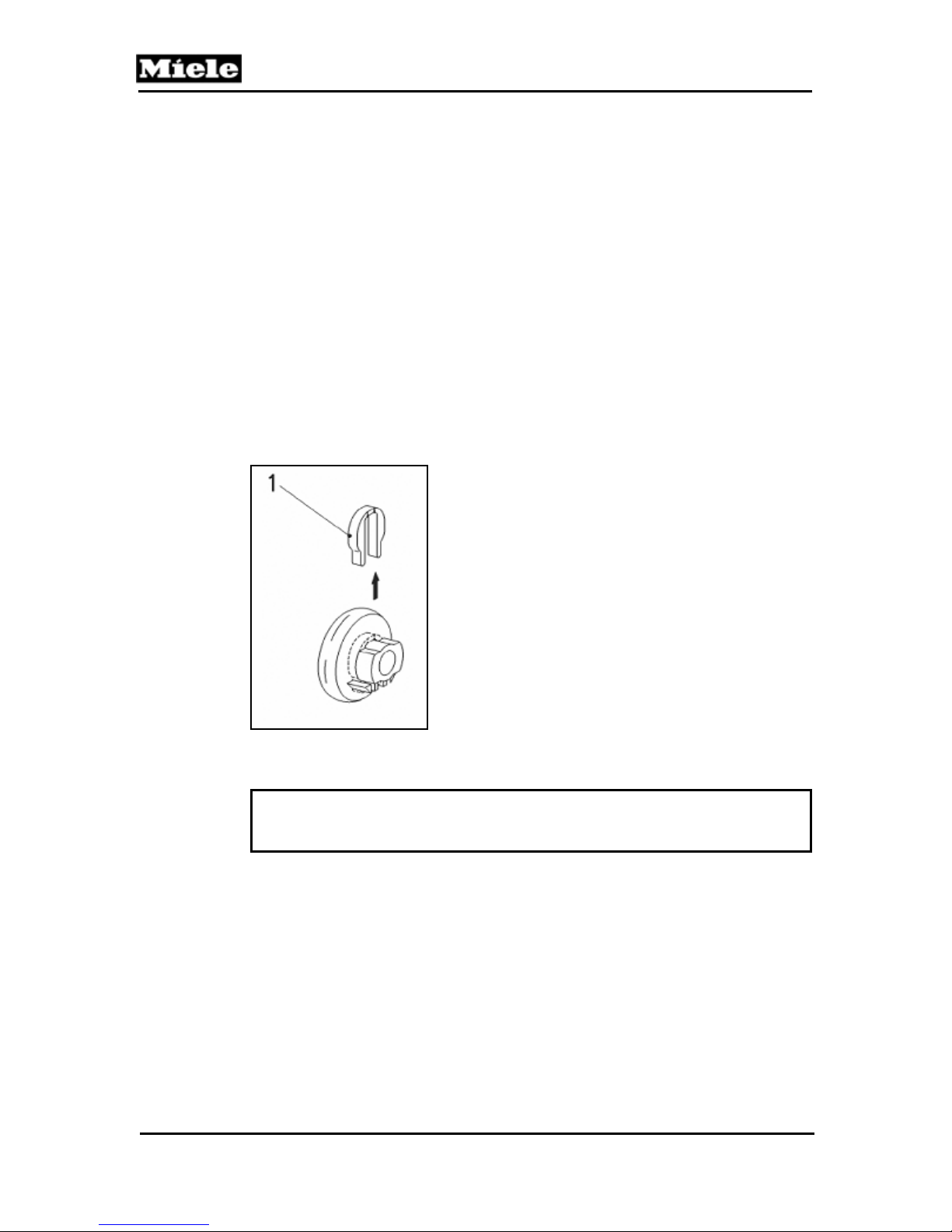
Technical Information
1. Open the door.
2. Remove the upper basket.
3. Pull the basket runner out far enough so that the clip (Figure 5-23, Item 1)
between the bolt on the cabinet wall and the basket runner is visible.
4. Remove the retaining clip by pushing it upward.
5. Remove the basket runner.
Figure 5-23: Retaining Clip
Note
In the event the retaining clip is damaged during removal, it must be
replaced with a new clip.
5.3.9 Water Level Check
1. Fully open the water supply.
2. Run the Pre-wash program, wait about 3 minutes.
G1000 / G2000 Dishwashers
80
Page 81
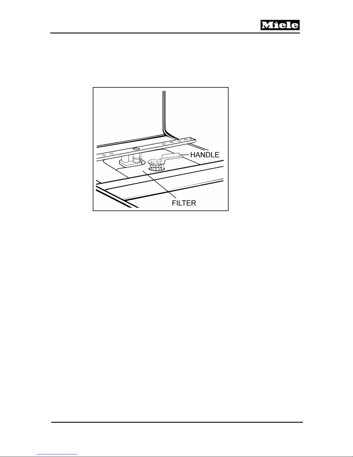
G1000 / G2000 Dishwashers
3. Do not cancel the program. Slowly open the door to observe the water
level in the bottom of the wash cavity.
If the water level is within close proximity of the filter handle (about 4 mm above the
filter), sufficient water has been taken in, Figure 5-24.
Figure 5-24: Water Level Reference
Technical Information
5.4 Water Paths
81
Page 82
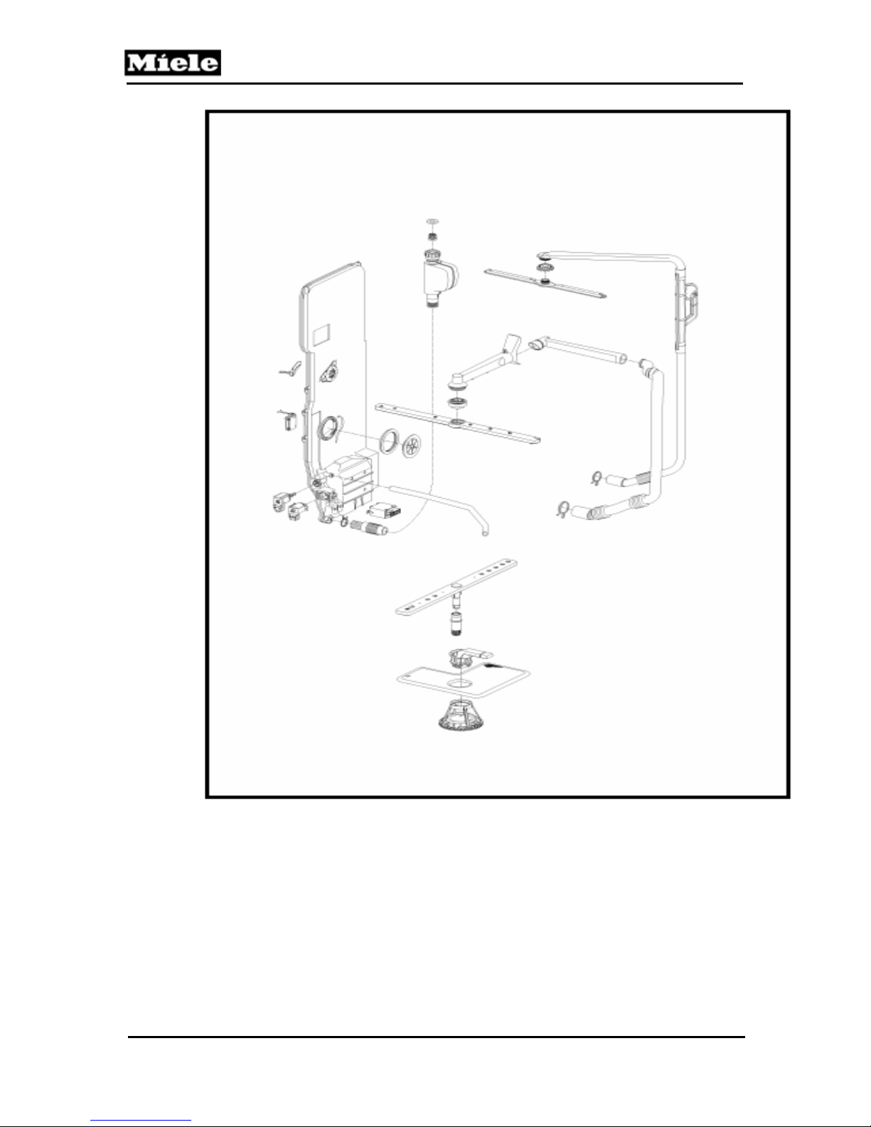
Technical Information
G1000 / G2000 Dishwashers
Figure 5-25: Water Path Layout
5.4.1 WaterProof System (WPS) Restrictor – Replacement
82
Page 83
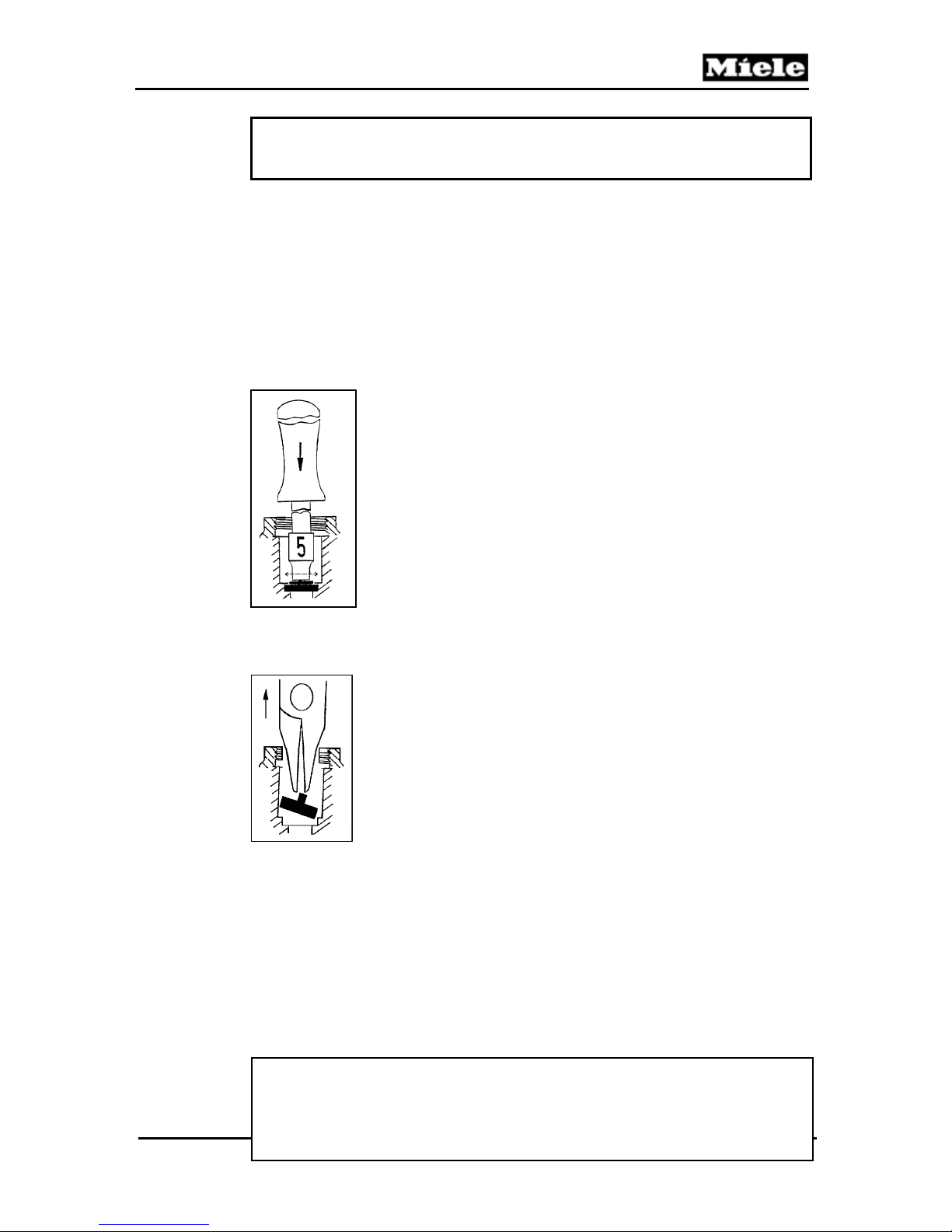
G1000 / G2000 Dishwashers
Technical Information
Note
For the G1000 and G2000 series, green restrictors (4.1 l/min) must be
fitted in the WaterProof System valve holder.
1. Shut off the water supply.
2. Disconnect the WPS at the plumbing supply connection.
3. Remove the sealing washer and filter from inside the WPS connection. Using a
5mm nut-driver; press and tilt the restrictor to the side; as shown in Figure 5-26.
4. Remove the Restrictor - Figure 5-27.
5. Install the new restrictor using a suitable 5 mm socket / nutdriver to seat it firmly
and evenly into place. Re-install the filter and sealing washer.
Figure 5-26: Tilting the Flow Restrictor
Figure 5- 27: Removing the Flow Restrictor.
5.4.2 WaterProof System (WPS) - Removal
Note
In the event the intake hose or water valves require replacement,
the WPS must be replaced as a complete assembly. Individual
replacement of the parts is not possible.
83
Page 84

Technical Information
1. Shut off the water supply.
2. Disconnect the WPS at the plumbing supply connection.
3. Remove the left side panel (5.1.1).
4. Remove the drip pan (5.1.2).
5. Disconnect the hose from the water.
6. Disconnect the electrical connection.
7. Unclip the wiring from the retainers. Release the WPS retainer from the rear of
the appliance and remove the WPS.
5.4.3 Flowmeter (circuit board) – Removal
Note
Only the circuit board on the flowmeter is the only part of the flowmeter
that can be replaced individually. In the event of mechanical failure within
the flowmeter the water inlet mixer must be replaced.
1. Remove the left side panel (5.1.1).
2. Release the circuit board retaining tab, and slide the board to remove it from the
water inlet mixer.
3. Disconnect the wiring.
5.4.4 Top Spray Arm Removal
G1000 / G2000 Dishwashers
1. Remove the cutlery tray if present.
2. Remove the top basket
3. Unscrew the screw connection and remove the spray arm.
5.4.5 Middle Spray Arm Removal
1. Remove the top basket.
2. Unscrew the screw connection and remove the spray arm.
84
Page 85

G1000 / G2000 Dishwashers
Technical Information
5.4.6 Bottom Spray Arm Removal
1. Remove the bottom basket.
2. Remove the spray arm.
5.4.7 Feed Pipe with Turbidity Sensor – Top Spray Arm, Removal
1. Remove the right side panel; see Side panel removal ( 5.1.1).
2. Disconnect the turbidity sensor plug connections.
3. Top spray arm removal (5.4.4).
4. Unscrew the counter nut.
5. Drip pan removal (5.1.2).
6. Disconnect the hose clip connection to the circulation pump.
5.4.8 Feed Pipe – Middle Spray Arm, Removal
1. Remove the right side panel. See Side panel removal (5.1.1).
2. Remove the top basket.
3. Dismantle the feed pipe on the rear panel inside the cabinet.
Note
To release the feed pipe in the rear panel through-feed area, hold the
stub at the rear and pull it while at the same time pushing in the seal
from the inside with a suitable screwdriver to reduce its cross-sectional
area.
4. Drip pan removal, (5.1.2).
5. Remove the right multi-plinth, see Multi-plinth removal, (5.3.5).
6. Disconnect the hose clip connection to the circulation pump.
5.4.9 Spray Arm Sensor Removal
1. Remove the right side panel; see Side panel removal, (5.1.1).
85
Page 86
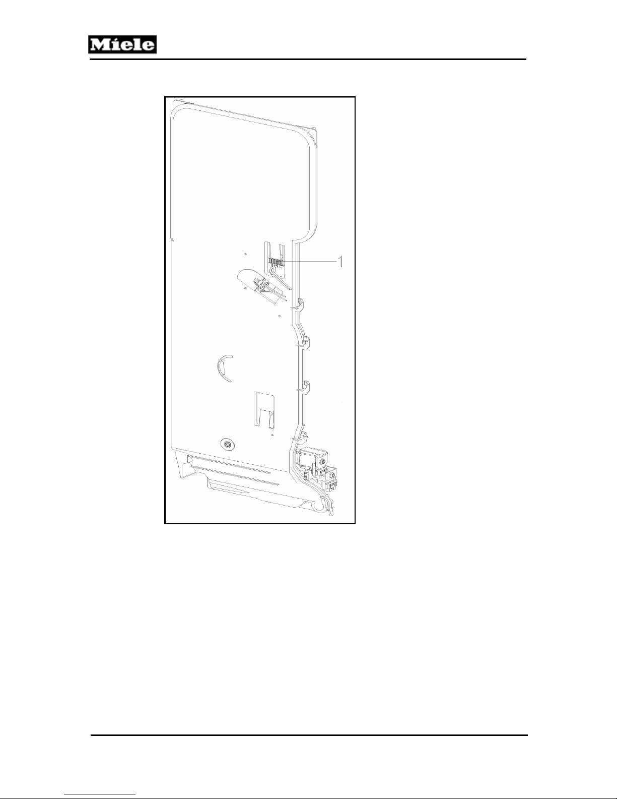
Technical Information
G1000 / G2000 Dishwashers
Figure 5-28: Spray Arm Sensor
2. Remove the spray arm sensor, Fig. 5-28, Item 1.
3. Disconnect its plug connection.
5.4.10 Water Inlet Mixer with Resin Chamber – Removal
86
Page 87
G1000 / G2000 Dishwashers
1. Unscrew the water inlet mixer vent connection inside the cabinet.
2. Unscrew the salt container cap.
3. Remove the sealing ring.
4. Empty the salt container.
5. Close the opening with the service cap (available through Miele).
6. Unscrew the retaining nut.
7. Remove the left side panel (5.1.1).
Warning
Do not tilt the unit onto its right side, as this would cause water to
run into the fan.
8. Remove the drip pan (5.1.2).
9. Remove the heating relay from the water inlet mixer.
10. Place a cloth or towel under the plug connections between the water
inlet mixer and the water softener.
11. Disconnect the connection with hose clip to the water inlet mixer from the resin
chamber.
12. Disconnect all plug connections.
13. Remove the wiring harness from its guide.
14. Pull off the salt container downwards in the direction of its connection stub.
15. Close the connection stub on the salt container with the service stopper
(available through Miele).
16. Disconnect the connection with hose clip to the sump.
17. Pull the water inlet mixer out of the seal to the sump, tilt it to the side and remove
it.
Reassemble by following these instructions in reverse order. The following should
also be noted:
1. Pre-fit the vent screw on the water inlet mixer and apply soap solution to it as a
slip lubricant.
2. Apply soap solution to the O-rings as a slip lubricant and fit them on the water
inlet mixer stubs.
3. Refit the wiring harness in its guides on the salt container and water inlet mixer.
4. Check all electrical components in the drip tray area for residual moisture.
Dry – as necessary.
Thoroughly remove any traces of salt / water that may have leaked.
After reassembly, fill the salt container with salt and water.
A short program, e.g. Quick wash 104°F, without load should be run to remove any
salt residues.Ensure all hardware is secured.
Technical Information
87
Page 88

Technical Information
1 Middle Spray Arm Sensor
2 Flowmeter Circuit Board
3 Lower Spray Arm Senso
4 Solenoid for EGS Valve
5 Solenoid for Reactivation
Figure 5-29: Water Intake Mixer Assembly and Related Components
5.4.11 EGS Valve Solenoid - Removal
1. Remove the left side panel (5.1.1).
2. Remove the drip pan (5.1.2).
3. Remove the connecting strip (5.3.4).
4. Disconnect the electrical connector from the solenoid.
5. Press the retaining lugs to the side
6. Remove the EGS valve upwards.
5.4.12 Reactivation Valve – Removal
G1000 / G2000 Dishwashers
88
Page 89

G1000 / G2000 Dishwashers
1. Remove the left side panel (5.1.1).
2. Remove the drip pan (5.1.2).
3. Remove the connecting strip (5.3.4).
4. Disconnect the electrical connector from the solenoid.
5. Twist the reactivation valve 90° clockwise.
6. Remove the reactivation valve upwards.
5.4.13 Salt Container - Removal
1. Remove the salt container cap from the cabinet interior.
2. Remove as salt water from the salt container.
3. Remove the sealing ring.
4. Close the opening with the service cap (available through Miele).
5. Unscrew the retaining nut.
6. Remove the left side panel (5.1.1).
7. Remove the drip pan (5.1.2).
8. Remove the heating relay from the water inlet mixer.
9. Place a cloth or towel under the plug connections between the water inlet mixer
and the water softener.
10. Disconnect the connection with hose clip to the water inlet mixer from the resin
chamber.
11. Disconnect the plug connections for the salt monitor from the salt container.
12. Remove the wiring harness from its guide.
13. Pull off the salt container in the direction of its connection stub.
14. Close the connection stub on the salt container with the service stopper
(available through Miele).
Reassemble by following these instructions in reverse order. The following should
also be noted.
1. Fit the salt container, center it with the retaining nut and screw tight.
2. Apply soap solution to the O-rings as a slip lubricant and fit them on the water
inlet mixer stubs.
3. Refit the wiring harness in its guides on the salt container and water inlet mixer.
4. Check all electrical components in the drip pan area for residual moisture. Dry –
as necessary.
5. Thoroughly remove any traces of salt / water that may have leaked.
6. After reassembly, fill the salt container with salt and water.
7. A short program, e.g. Quick wash 104°F, without load should be run to remove
any salt residues.
8. Ensure all hardware is secured.
5.4.14 Circulation Pump - Removal
1. Remove the motor holder retaining screw from the rear panel.
Technical Information
89
Page 90
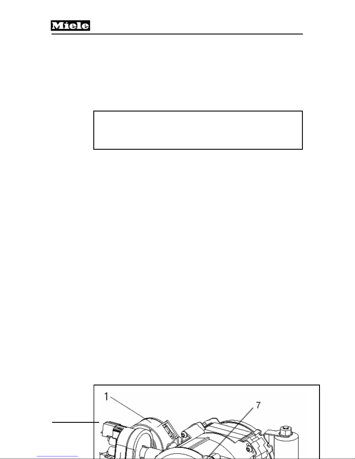
G1000 / G2000 Dishwashers
Technical Information
2. Remove the drip pan (5.1.2).
3. Disconnect the electrical connectors.
4. Disconnect the plumbing connections for the feed pipes to the top and
middle spray arms.
5. Disconnect the plumbing connections between the circulation pump and the
sump assembly.
6. Remove the circulation pump.
Important
When installing the circulation pump, the seal must be installed on
the pump. Then slide the circulation pump (with seal installed on the
pump) into the sump housing and secure.
90
Page 91

G1000 / G2000 Dishwashers
1 Slide Shutter Motor
2 Heater Pressure Switch
3 Heater Element
4 Speed Sensor
5 Electrical Connection
6 Capacitor
7 Housing Cap
Figure 5-30: Circulation Pump and Related Components (Typical)
5.4.15 Circulation Pump - Service
All procedures in this section begin with removal of the circulation pump from the
Technical Information
91
Page 92

G1000 / G2000 Dishwashers
Technical Information
appliance.
Refer to Figure 5-30, as directed.
Important
During reassembly of the circulation pump ensure:
1. A new sealing ring is installed
2. The sealing ring is seated correctly in the pump housing cap
3. The pump housing cap is evenly seated
4. The cap retaining screws are secure
5. The fastening clips are pressed over the retaining lugs
5.4.15.1 Pump Cap Removal / Heater Element – Access
1. Remove the cap retaining screws.
2. Release the retaining clips by pushing the clip to the side, while pressing down
the cap.
3. Lightly twist the cover and pull away from the housing to remove.
5.4.15.2 Slide Shutter Removal
1. Circulation pump removal (5.4.14).
2. Heater Pressure Switch removal (5.4.15.7).
3. Pump housing cap removal (5.4.15.1).
92
Page 93
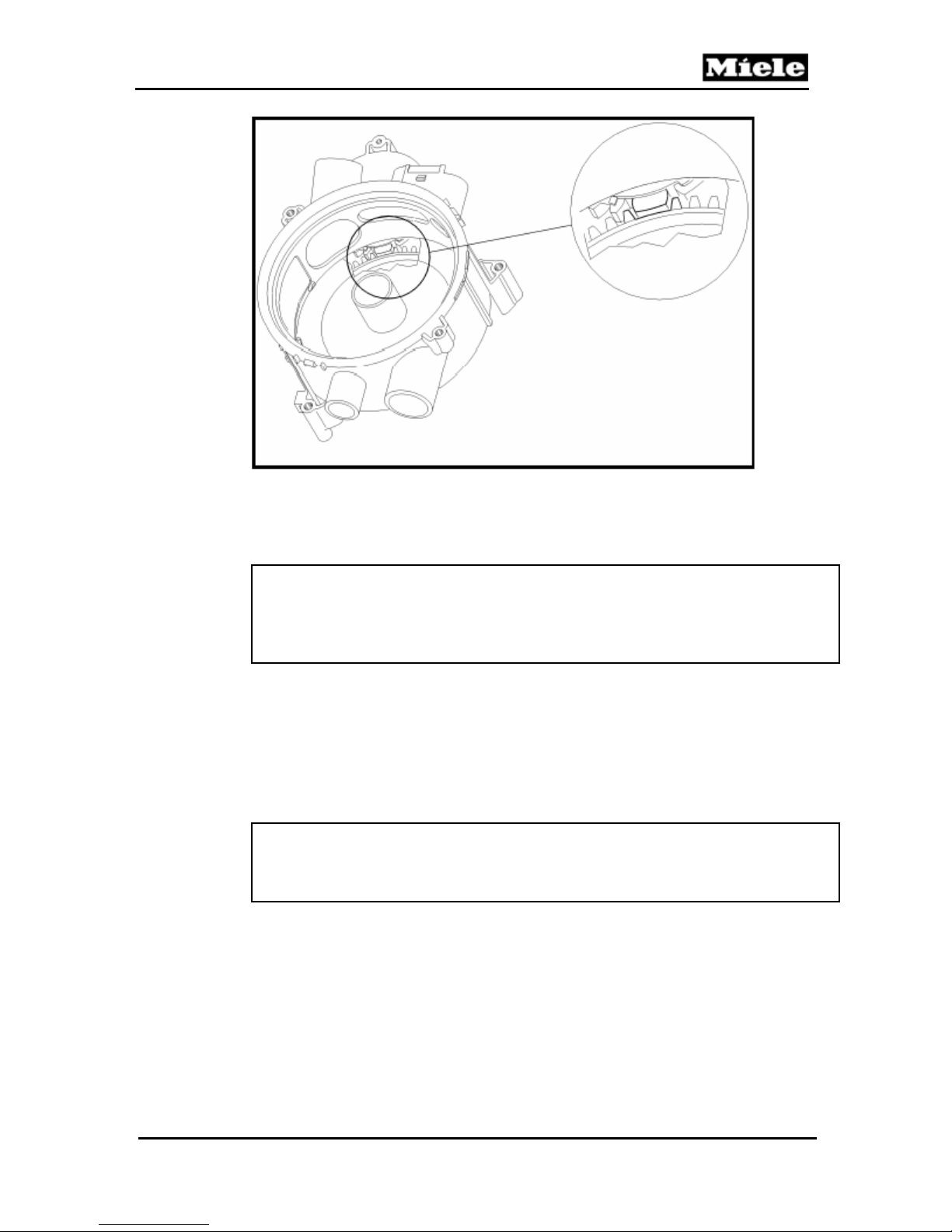
G1000 / G2000 Dishwashers
Figure 5-31: Slide Shutter Assembly
Technical Information
Note
The slide shutter can only be removed or fitted when the drive cog wheel
is turned with the double tooth in the position shown, see Fig. 5-31.
4. Turn the drive cog wheel to bring the double tooth to the desired position as
follows: Insert a small screwdriver in one of the holes on the cam (linked to the
slide shutter control motor). Turn the cam until the slide shutter can be removed.
5. Remove the slide shutter.
Warning!
Before refitting the slide shutter in the pump housing, make sure that the
double tooth on the drive cog wheel points to the arrow on the housing.
5.4.15.3 Drive Removal
1. Circulation pump removal (5.4.14).
93
Page 94
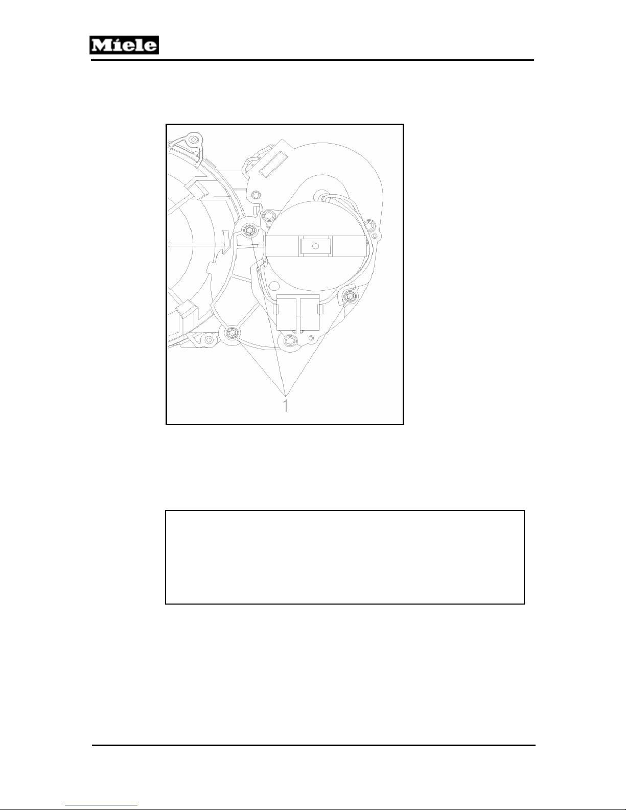
Technical Information
2. Pump housing cap removal (5.4.15.1).
3. Slide shutter removal (5.4.15.2).
G1000 / G2000 Dishwashers
Figure 5-32: Drive Cam
4. Remove the drive retaining screws, Fig. 5-27, Item 1.
Warning!
When refitting, check that the O-ring is seated correctly on the drive
cam.
Before refitting the slide shutter in the pump housing, make sure that
the double tooth on the drive cog wheel points to the arrow on the
housing.
94
Page 95

G1000 / G2000 Dishwashers
p
5.4.15.4 Pump Impeller Removal
1. Circulation pump removal (5.4.14).
2. Pump housing cap removal (5.4.15.1).
3. Hold the shaft base with suitable pliers and unscrew the pump impeller clockwise.
5.4.15.5 Pump Housing Removal
1. Circulation pump removal (5.4.14).
2. Pump housing cap removal (5.4.15.1).
3. Pump impeller removal (5.4.15.4).
4. Remove the retaining screws.
5. Turn the pump housing counterclockwise to its stop.
6. Lift the pump housing from its guide.
Technical Information
5.4.15.6 Capacitor Removal
1. Circulation pump removal (5.4.14).
2. Use a socket wrench to release the nut on the capacitor holder.
3. Remove the capacitor.
4. Disconnect its plug connections.
5.4.15.7 Heater Pressure Switch Removal
1. Circulation pump removal (5.4.14).
2. Press the retaining lugs to one side with a suitable screwdriver.
3. Disconnect the plug connections.
4. Remove the pump’s heater pressure switch.
Warning!
To avoid leakages, the sealing rings must always be fitted on the pump’s
heater
ressure switch connection stubs.
5.4.15.8 Speed Sensor Removal
95
Page 96
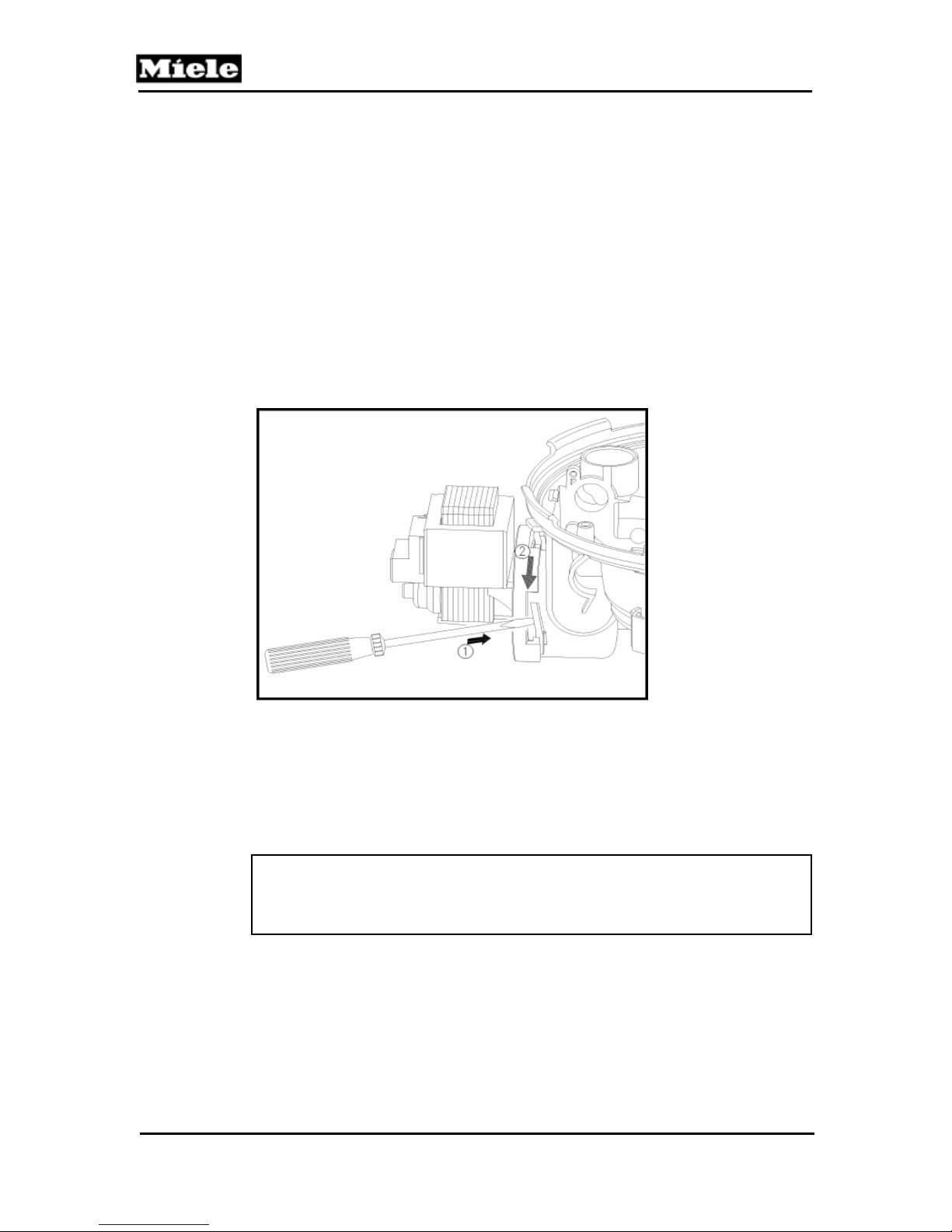
Technical Information
1. Circulation pump removal (5.4.14).
2. Lift the PCB slightly with a pair of needle nose pliers so that it can be gripped with
the hand.
3. Turn the PCB 90° clockwise and remove it.
5.4.16 Drain Pump Removal
1. Remove the non-return valve from the sump under the filter combination.
2. Cover plate removal (5.3.3).
3. Disconnect the pump plug connections.
G1000 / G2000 Dishwashers
Figure 5-33: Drain Pump Retaining Clip
4. Open the safety retainer clip with a screwdriver, Fig. 5-33, Pos. 1.
5. Turn the pump clockwise and pull it from its holder, Fig. 5-33, Pos. 2.
5.4.17 Float Switch Removal
Note
When refitting, apply a little water or soap solution to the pump seal as
a slip lubricant. After fitting, check all the pump fastening points.
96
Page 97
G1000 / G2000 Dishwashers
1. Open the door.
2. Remove the bottom basket.
3. Remove the filter combination.
4. Remove as much residual water as possible from the sump and drain hose.
5. Lay the dishwasher on its back.
5. Drip pan removal (5.1.2).
6. Pull off the float switch.
7. Disconnect its plug connections.
Technical Information
Note
When refitting the float, make sure that the side with the Mat. No.
faces downwards.
5.4.18 Sump Removal
1. Remove as much residual water as possible from the sump and drain hose.
2. Open the door.
3. Remove the bottom basket.
4. Remove the bottom spray arm.
5. Unscrew the bottom spray arm flange.
6. Remove the filter combination.
7. Lay the dishwasher on its back.
8. Drip pan removal, 5.1.2.
9. Remove the float switch.
10. Disconnect the hoses.
11. Disconnect the NTC sensor connections.
12. Drain pump removal (5.4.16).
13. Circulation pump removal (5.4.14).
14. Remove the heating wiring harness from the cable guide.
15. Unscrew the hose clip and remove it.
16. Remove the sump by pulling down strongly and evenly on the drain pump or
circulation pump connections.
17. Remove the sealing ring.
Note
When refitting, the following should be noted;
1. Fit the sealing ring on the metal flange on the cabinet.
2. Apply liquid detergent as a slip lubricant to the outer surface of
the seal.
3. Apply liquid detergent as a slip lubricant to the inside of the
97
Page 98

Technical Information
G1000 / G2000 Dishwashers
Warning!
To avoid possible leakages later, the clip on the sump should not be
overtightened.
5.4.19 NTC Temperature Sensor Removal
98
Page 99
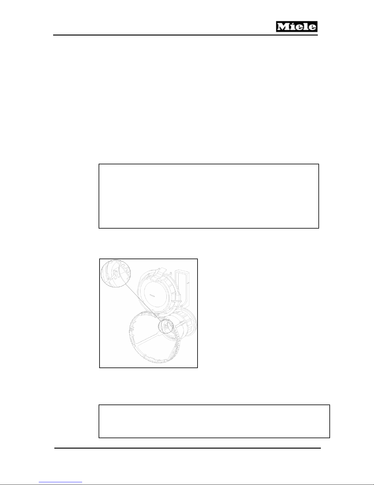
G1000 / G2000 Dishwashers
1. Open the door.
2. Remove the bottom basket.
3. Remove the bottom spray arm.
4. Remove the filter combination.
5. Remove as much residual water as possible from the sump and drain hose.
6. Lay the dishwasher on its back.
7. Remove Drip pan, 5.1.2
8. Disconnect the NTC temperature sensor plug connections.
9. Remove the NTC temperature sensor.
10. Remove the sealing ring.
5.4.20 Filter Combination Dismantling
Technical Information
Note
During reassembly, a locking piece must be fitted to prevent the filter
combination from falling apart, see Filter combination assembly (with
locking piece) (5.4.22).
As an alternative, the micro fine filter and the handle piece (crown
coarse filter) must be exchanged together, see Filter combination
assembly (new micro fine filter and handle) (5.4.21).
1. Open the filter cap.
Figure 5-34: Combination Filter
Note
If the filter combination is already held together with a locking piece, this
must be broken open and removed.
99
Page 100
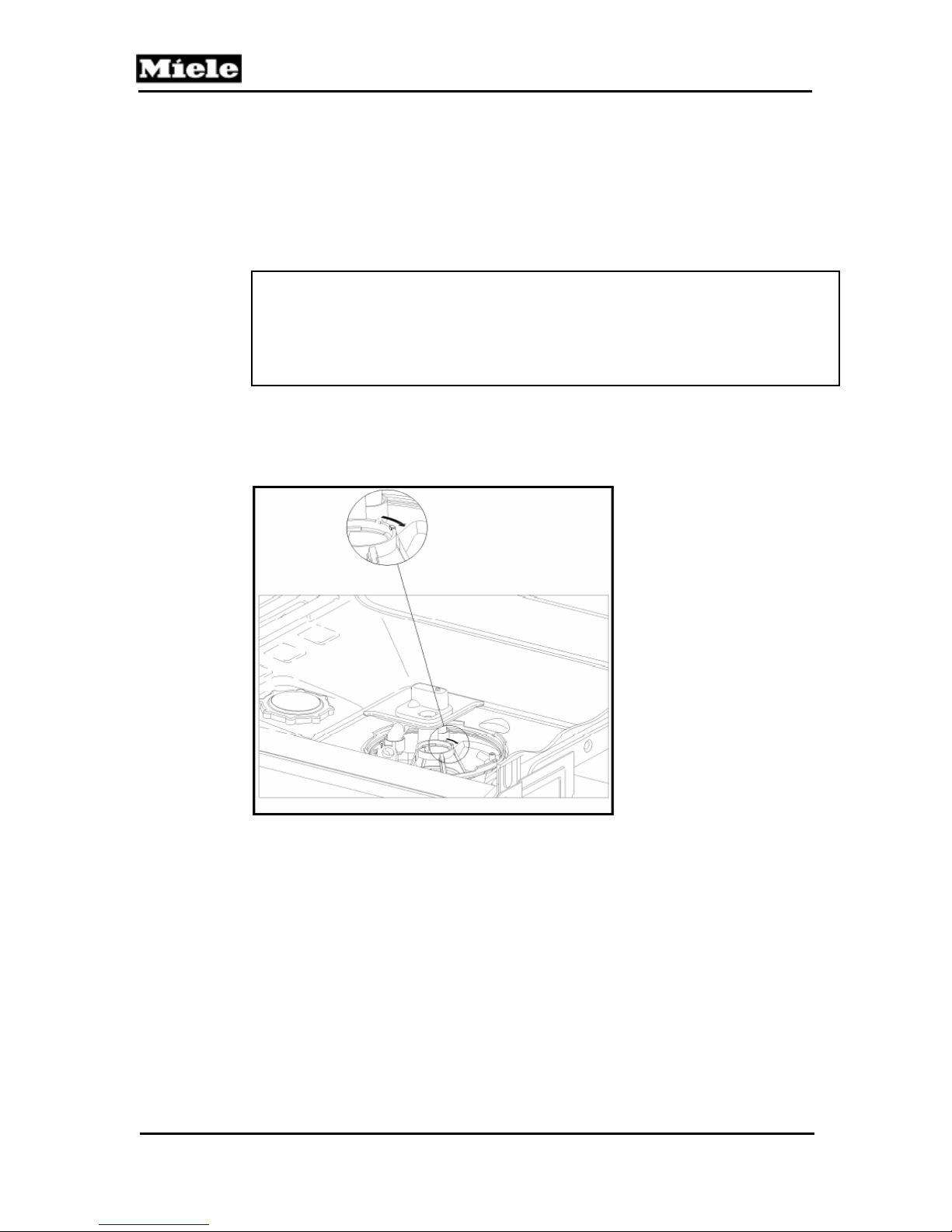
G1000 / G2000 Dishwashers
Technical Information
2. Place a screwdriver on the retaining clip spring, Fig. 5-34, and press against it.
3. Turn the handle clockwise and release the filter combination clip connection.
5.4.21 Filter Combination Assembly (New Micro Fine Filter and Handle)
Note
During assembly, the dishwasher is used as a guide.
If a new micro fine filter and handle (crown coarse filter) are used, a
locking piece is not required.
1. Place the micro fine filter in the sump. Ensure that the lug is positioned towards
the rear of the machine.
Figure 5-35: Micro Fine Filter Installation
2. Turn the micro fine filter clockwise as far as possible, Fig. 5-35.
3. Place the large surface area fine filter in position.
100
 Loading...