

Page 1
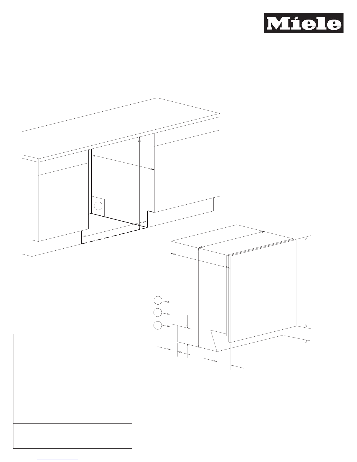
Product and Cut-out Dimensions
G2000 Series Dishwashers
Fully Integrated Models
22 7/16" min.
Water & Electrical
Connection
Location
C
Location Codes
Cutout (2 1/4" x 4") for water, drain
C -
and electric pass-through. Adjust
according to water and drain location.
5 foot flexible drain hose connects
D -
lower center rear.
5 foot - 120 Volt - 15 Amp 3-wire
E -
molded plug power supply connects
lower left rear.
5 foot "Double Waterproof" flexible
W -
water intake hose connects lower
center rear.
Notes
• All installations must be done in
accordance with local codes
23 5/8"
33 1/4" - 35 3/4"
D
W
E
1 3/8"
22 7/16"
5 1/8"
23 9/16"
27 1/8" - 31 7/8"
33 1/4" - 35 3/4"
1 3/8" - 8 5/8"
4 1/2"
NOTE: Drawing is not to scale.
SPECIFICATION SHEETS 010106
Page 2
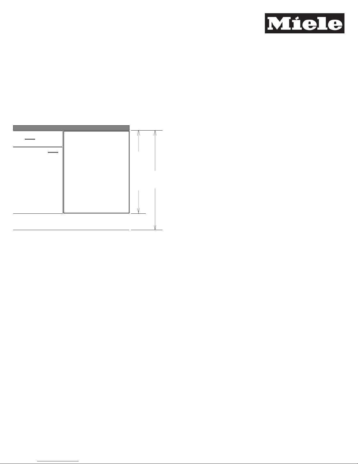
Front Panel Information
G2000 Fully Integrated Models
Custom Panel Installations
Some Miele dishwashers do not come equipped with a front panel. These dishwashers are designed to accept a
custom door panel supplied by the cabinet maker. Miele has a unique panel integration system which allows the
dishwasher to align with the surrounding cabinets.
Panel size is determined in the following manner:
Miele
Fully
Integrated
Dishwasher
TKH
HTC
Panel Height
Width: 23 7/16" in all cases
Thickness: 3/4" in all cases
Height:Determined using the following calculation:
Panel Height = HTC - TKH
HTC = Height to the underside of countertop
TKH = T oe-kick height
Note: Control panel is along the top edge of the unit. It
is not visible when the unit is closed.
A handle MUST be located on the front panel in
order to open the unit
Maximum panel height: 31 7/8"
Minimum panel height: 27 3/16"
Maximum panel weight: 21 Pounds
GFVi Installations
Miele offers pre-fabricated stainless steel panels for all fully integrated units. These panels are designed for various
toe-kick heights and offer a choice of handle options.
NOTE: Drawing is not to scale.
SPECIFICATION SHEETS 010106
Page 3
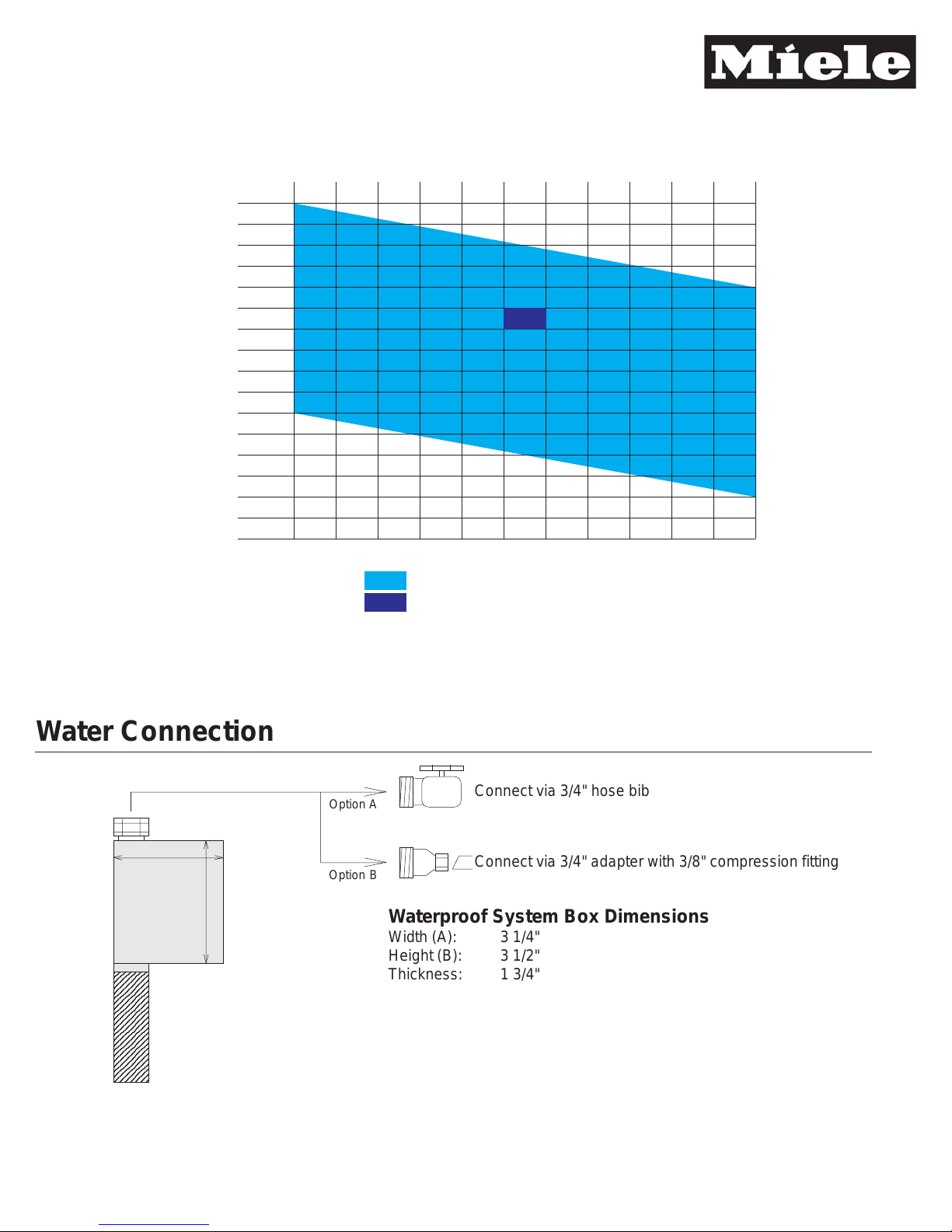
Installation Information
8
8
8
8
8
8
8
8
8
8
8
8
8
8
8
8
8
8
8
8
8
8
G2000 Dishwashers
Height to underside of countertop
1 1/2
2
1
/2
2
3
1
/2
3
4
1
/2
4
5
1
/2
5
6
Toekick height
6 1/2
7
7 1/2
8
8 1/2
9
33 1/4 33 3/4 34
Acceptable combinations
T ypical American installation
34 1/4
34 3/4
34 1/233 1/2
35
35 1/4
35 1/2
35 3/4
Water Connection
Dimension (A)
234567
234567
234567
234567
234567
234567
234567
234567
234567
234567
234567
234567
234567
234567
234567
234567
234567
234567
234567
234567
234567
234567
Temperature: 110° - 130° F
Pressure: 4.5 - 145 PSI
Drain hose: 7/8" ID - 5 feet long
Waterproof System
Dimension (B)
Option A
Option B
Connect via 3/4" hose bib
Connect via 3/4" adapter with 3/8" compression fitting
Waterproof System Box Dimensions
Width (A): 3 1/4"
Height (B): 3 1/2"
Thickness: 1 3/4"
Cutout: 2 1/4" x 4"
NOTE: Waterproof system box should ONLY be
installed in a vertical manner to prevent build-up of
water within box and possible leakage.
NOTE: Drawing is not to scale.
SPECIFICATION SHEETS 010106
 Loading...