

Page 1
Mobile unit E 928 for instruments for robotic-assisted surgery
Please read the Warning and Safety instructions in the Operating Instructions for your PG 8527/PG 8528 washer-disinfector carefully. You should only reprocess
,
instruments/medical products in this mobile unit if they have been declared as suitable for machine reprocessing by the manufacturer. Please also observe the
manufacturer's care instructions.
The E 928 mobile unit must only be operated with the ROBOTVARIO programme. This programme is not supplied as standard and must be programmed
retrospectively into the Profitronic unit by Miele.
The setting of the mobile unit will be carried out during commissioning by Miele. The coding must be matched when using automatic mobile unit recognition.
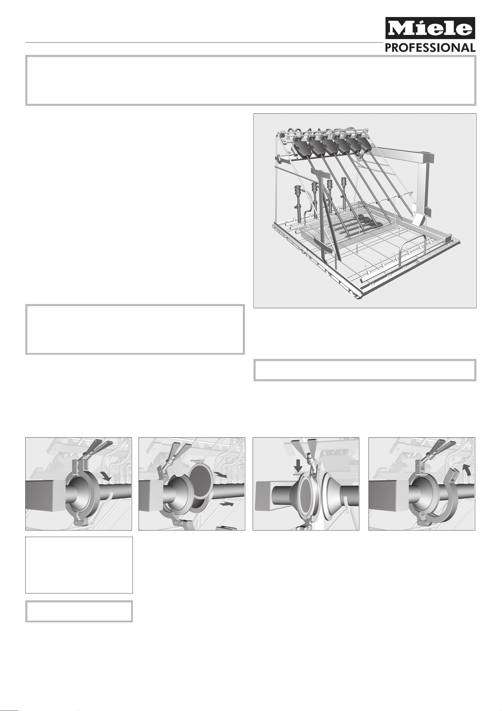
Items supplied:
Mobile unit E 928 with 6 holders for 8 mm shafted instruments for robotic-assisted
surgery, H 560, W 640, D 790 mm with magnetic strip for automatic mobile unit
recognition.
Supplied as separate items:
2 filter plates
–
6 x E 443 injector sleeves with screw thread for instrumentsØ8-8.5mm,
–
121 mm long, Ø 11 mm, cap with Ø 10 mm opening
6 x E 448 silicone hoses, 300 mm, with Luer lock adapters \ for Luer locks ]
–
3 x E 452 injector jets Ø 2.5 mm, 60 mm long
–
Accessory available to order:
E 499, holder for Veress cannulae
–
Areas of application:
8 mm shafted instruments for robotic-assisted surgery can be reprocessed in the
E 928 mobile unit using the ROBOTVARIO programme and Mucapur
ROBOTVARIO cleaning agent.
There are 15 screw connectors in the rear area of the mobile unit for reprocessing
other items used in connection with robotic-assisted surgery.
These are equipped with blanking screws ex-works. Where necessary, the screw
connectors can be fitted with injector jets, injector sleeves or silicone hoses
instead of the blanking screws.
To ensure a suitable standardised spray pressure for all connections, all
,
screw connectors must be fitted with jets, adapters, sleeves or blanking
screws.
Damaged jets, adapters or sleeves etc. must not be used.
Empty jets, etc. do not have to be replaced with blanking screws.
Before loading the machine and before starting a programme, please check
that:
– the mobile unit is correctly fitted into the cabinet and that it has connected
correctly with the water intake of the washer-disinfector.
– the filter plate has been cleaned and is located in the water intake pipe.
For validation purposes please make sure that you follow the loading
instructions given on the template.
Cleaning the water inlet filter plate
^
A filter plate is located in the water
intake pipe in front of the double pipe
connections for the shafted
instruments.
It prevents residues from other
disciplines getting into the lumen of
the instruments.
,
The filter plate must be cleaned
before every programme.
Pull the right side of the water intake
pipe to the side.
^
Remove the filter plate.
^
Soiling and deposits should be
rinsed off under running water. If
necessary a suitable soft brush can
be used.
^
Blow out the filter plate with
compressed air from the underside
against the flow direction.
^
Place the filter plate in the left side of
the holder and hold it securely at the
top.
^
Push the right side of the water intake
pipe towards the left to close the
holder.
^
Place the clamp around the rim of the
holder and screw it down with the
wing nut.
^
Unscrew the wing nut on the clamp
around the filter plate holder and
open the clamp.
Miele Company Ltd., Fairacres, Marcham Road, Abingdon, Oxon, OX14 1TW, Tel 0845 365 0555, Fax 0845 365 0777,
Internet: http://www.miele.co.uk /
! 0366 Alteration rights reserved / Publication date: 2013-06-17
M.-Nr. 09 507 430 / 00 en
Page 2
Mobile unit E 928 for instruments for robotic-assisted surgery
Manual pre-cleaning
Pre-treatment at the place of use
,
as well as preparation for machine
reprocessing must be carried out in
accordance with the instrument
manufacturer's instructions.
In addition, immediately after arrival
in the CSSD of instruments which
have been filled with solution in the
operating room:
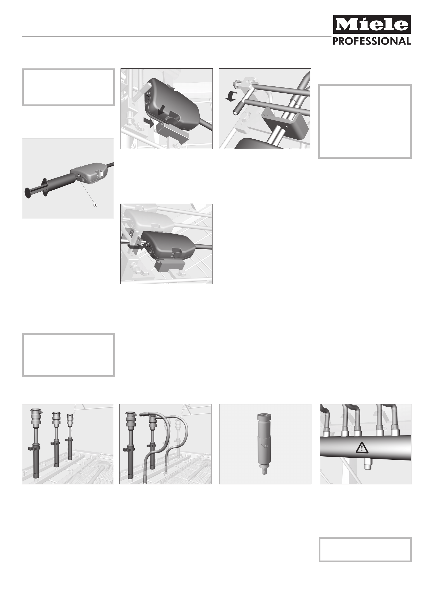
Arranging and connecting the shafted instruments
Place the instrument into the holder
^
from above.
The shaft should be positioned in the
recess of the lower strut.
Open the functional ends of the in
^
strument.
-
When all instruments have been loa
^
ded, move the connector retaining
bar and click it into position.
The retaining plates for the water con
nectors will be held in place by the bar.
Any unused water connectors must also
be positioned underneath the bar.
Routine checks for consistency of
cleaning performance
Instruments should be dismantled at
random after their last operative use
and machine reprocessing. Cap the
Bowden cables at the sprocket and
remove the distal functional part.
Examine the inner distal cylinder,
through which the Bowden cables
pass to the functional end, under a
microscope and use protein analysis
for residual soil in accordance with
current guidelines.
-
-
Remove the solution from the
^
instruments.
Refill the instruments with 3%
^
Mucapur ROBOTVARIO solution and
leave to take effect for 30 minutes.
During this 30 minute activation time:
Empty the Mucapur ROBOTVARIO
^
solution out of the instruments and
replace with fresh solution.
^ Wait for an activation time of
5 minutes.
^ Repeat the procedure as described
five more times.
^ After this prepare the instruments in
accordance with the manufacturer's
recommendations.
A visual check of the instruments,
particularly the distal functional ends,
to ensure that they appear clean,
must be carried out before the
instruments are arranged in the
E 928 mobile unit.
^ Plug the double pipe connection into
the instrument's rinsing attachment.
Trocar sleeves Veress cannulae Test point for cleaning pressure mea
surement
^
Insert the trocar sleeves into the
injector sleeves.
^
Connect the trocar sleeve at the side
with an E 448 hose adapter.
^
Screw the hose adapter to the rinsing
channel.
An E 499 holder is required in order to
reprocess Veress cannulae (available to
order).
The holder comes with its own
instructions.
Cleaning pressure for performance
checks and validation according to DIN
EN ISO 15883 can be measured using
this test point.
^
To measure cleaning pressure,
replace the sealing screw with a Luer
lock adapter, e.g. E 447.
-
Ensure that no instruments, rinsing
channels etc. are connected to the
test point.
 Loading...