

Page 1
Operating and installation instructions
Cooker hoods
DA 362, DA 362 EXT
DA 372, DA 372 EXT
To avoid the risk of accidents
or damage to the appliance it is
essential to read these instructions
before it is installed or used for the first time.
GiW
M.-Nr. 05 889 281
Page 2

Contents
Caring for the environment . . . . . . . . . . . . . . . . . . . . . . . . . . . . . . . . . . . . . . . . . . 3
Warning and Safety instructions . . . . . . . . . . . . . . . . . . . . . . . . . . . . . . . . . . . . . 4
Description of the appliance. . . . . . . . . . . . . . . . . . . . . . . . . . . . . . . . . . . . . . . . . 8
Description of the functions . . . . . . . . . . . . . . . . . . . . . . . . . . . . . . . . . . . . . . . . 10
Operation
Master switch. . . . . . . . . . . . . . . . . . . . . . . . . . . . . . . . . . . . . . . . . . . . . . . . . . . . . 11
Joystick . . . . . . . . . . . . . . . . . . . . . . . . . . . . . . . . . . . . . . . . . . . . . . . . . . . . . . . . . 11
To switch the fan on . . . . . . . . . . . . . . . . . . . . . . . . . . . . . . . . . . . . . . . . . . . . . 11
To select a power level . . . . . . . . . . . . . . . . . . . . . . . . . . . . . . . . . . . . . . . . . . . 11
To switch the fan off . . . . . . . . . . . . . . . . . . . . . . . . . . . . . . . . . . . . . . . . . . . . . 11
Hob lighting . . . . . . . . . . . . . . . . . . . . . . . . . . . . . . . . . . . . . . . . . . . . . . . . . . . 12
Run-on option . . . . . . . . . . . . . . . . . . . . . . . . . . . . . . . . . . . . . . . . . . . . . . . . . . . . 12
Filter operating hours counter . . . . . . . . . . . . . . . . . . . . . . . . . . . . . . . . . . . . . . . . 13
Reading the filter operating hours counter. . . . . . . . . . . . . . . . . . . . . . . . . . . . 13
Setting and altering the operating hours counter. . . . . . . . . . . . . . . . . . . . . . . 14
Cleaning and care
Housing . . . . . . . . . . . . . . . . . . . . . . . . . . . . . . . . . . . . . . . . . . . . . . . . . . . . . . . . . 16
Grease filter . . . . . . . . . . . . . . . . . . . . . . . . . . . . . . . . . . . . . . . . . . . . . . . . . . . . . . 16
Fitting and replacing the charcoal filter . . . . . . . . . . . . . . . . . . . . . . . . . . . . . . . . . 18
Changing a lamp . . . . . . . . . . . . . . . . . . . . . . . . . . . . . . . . . . . . . . . . . . . . . . . . . . 19
Appliance dimensions. . . . . . . . . . . . . . . . . . . . . . . . . . . . . . . . . . . . . . . . . . . . . 20
Installation
Fitting the non-return flap. . . . . . . . . . . . . . . . . . . . . . . . . . . . . . . . . . . . . . . . . . . . 22
Exhaust connection . . . . . . . . . . . . . . . . . . . . . . . . . . . . . . . . . . . . . . . . . . . . . . . . 22
Building in . . . . . . . . . . . . . . . . . . . . . . . . . . . . . . . . . . . . . . . . . . . . . . . . . . . . . . . 23
Preparation for extraction. . . . . . . . . . . . . . . . . . . . . . . . . . . . . . . . . . . . . . . . . . . . 24
Preparation for recirculation. . . . . . . . . . . . . . . . . . . . . . . . . . . . . . . . . . . . . . . . . . 24
Connection for recirculation mode. . . . . . . . . . . . . . . . . . . . . . . . . . . . . . . . . . . . . 24
Fitting the joystick . . . . . . . . . . . . . . . . . . . . . . . . . . . . . . . . . . . . . . . . . . . . . . . . . 25
Joystick extension. . . . . . . . . . . . . . . . . . . . . . . . . . . . . . . . . . . . . . . . . . . . . . . 25
Electrical connection . . . . . . . . . . . . . . . . . . . . . . . . . . . . . . . . . . . . . . . . . . . . . . . 26
Connection for air extraction . . . . . . . . . . . . . . . . . . . . . . . . . . . . . . . . . . . . . . . 27
Condensate trap . . . . . . . . . . . . . . . . . . . . . . . . . . . . . . . . . . . . . . . . . . . . . . . . . . 28
Electrical connection . . . . . . . . . . . . . . . . . . . . . . . . . . . . . . . . . . . . . . . . . . . . . 29
After Sales Service . . . . . . . . . . . . . . . . . . . . . . . . . . . . . . . . . . . . . . . . . . . . . . . 30
Technical data . . . . . . . . . . . . . . . . . . . . . . . . . . . . . . . . . . . . . . . . . . . . . . . . . . . 31
2
Page 3
Caring for the environment
Disposal of the packing
material
The transport and protective packing
has been selected from materials which
are environmentally friendly for
disposal, and can normally be
recycled.
Packaging (e.g. cling film, polystyrene)
and plastic wrappings must be kept out
of the reach of babies and young
children. Danger of suffocation!
Dispose of or recycle all packaging
materials safely as soon as possible.
Disposal of your old appliance
Electrical and electronic appliances
often contain materials which, if
handled or disposed of incorrectly,
could be potentially hazardous to
human health and to the environment.
They are, however, essential for the
correct functioning of your appliance.
Please do not therefore dispose of your
old appliance with your household
waste.
Please dispose of it at your local
community waste collection / recycling
centre and ensure that it presents no
danger to children while being stored
for disposal.
It should be unplugged or disconnected
from the mains electricity supply by a
competent person. If connected by a
plug, the plug must be rendered
useless and the cable cut off directly
behind the appliance to prevent
misuse. See the "Warning and Safety"
section of this booklet for further details.
3
Page 4
Warning and Safety instructions
Technical safety
This appliance complies with all
relevant local and national safety
requirements. Inappropriate use
can, however, lead to personal injury
and damage to property.
To avoid the risk of accidents and
damage to the appliance, please
read these instructions carefully
before using it for the first time. They
contain important information on the
safety, installation, use and
maintenance of the appliance.
Keep these operating instructions in
a safe place and ensure that all
users are familiar with the contents.
Pass them on to any future owner of
the appliance.
Correct usage
This appliance is intended for
domestic use only.
It is not a toy! To avoid the risk of injury
do not let children play with it or use the
controls. Supervise its use by the
elderly or infirm.
The manufacturer cannot be held liable
for damage caused by improper or
incorrect use of the appliance.
In countries where there are areas
which may be subject to infestation
by cockroaches or other vermin, pay
particular attention to keeping the
appliance and its surroundings in a
clean condition at all times. Any
damage which may be caused by
cockroaches or other vermin will not be
covered by the guarantee.
the voltage and frequency details given
on the data plate correspond with the
on-site electricity supply; otherwise the
appliance could get damaged. Consult
a qualified electrician if in any doubt.
when continuity is complete between
the appliance and an effective earthing
system which complies with local and
national safety regulations. It is most
important that this basic safety
requirement is present and regularly
tested, and where there is in any doubt,
the household wiring system should be
inspected by a qualified electrician.
The manufacturer cannot be held liable
for the consequences of an inadequate
earthing system (e.g. electric shock).
by a suitably qualified and competent
person in accordance with national and
local safety regulations. Repairs and
other work by unqualified persons
could be dangerous. The manufacturer
cannot be held liable for unauthorised
work.
Ensure that current is not supplied to
the appliance until after maintenance or
repair work has been carried out.
such as ships, caravans, aircraft etc. if
a risk assessment of the installation has
been carried out by a suitably qualified
engineer.
Before connecting the appliance to
the mains supply, make sure that
The electrical safety of this
appliance can only be guaranteed
Installation, maintenance and
repair work may only be carried out
This equipment may only be
installed in mobile installations
4
Page 5

Warning and Safety instructions
The appliance is only completely
isolated from the electricity supply
when:
it is switched off at the wall socket
–
and the plug removed, or
the mains fuse is withdrawn, or
–
the fuse from the fused spur
–
connection unit is withdrawn, or
the screw-out fuse is removed (in
–
countries where this is applicable).
Do not connect the appliance to
the mains electricity supply by an
extension lead.
Extension leads do not guarantee the
required safety of the appliance (e.g.
danger of overheating).
For appliances with an external
motor fitted (...EXT models) the
connection of the two units must be
made using the connection cable and
the plug connectors.
These models may only be combined
with a Miele external motor.
Use
Never use an open flame beneath
the cooker hood. To avoid the
danger of fire, do not flambé or grill
over an open flame under the cooker
hood. When switched on, the cooker
hood could draw flames into the filter.
Fat particles drawn into the cooker
hood present a fire hazard.
When using the cooker hood over
a gas hob, ensure that any burners
in use are always covered by a pan;
otherwise flames could be drawn up by
the suction of the cooker hood, parts of
which could then be damaged.
Always switch the cooker hood on
when a cooking zone is in use,
otherwise condensation may collect in
the hood, which could cause corrosion.
When cooking with oil or fat, chip
pans and deep fat fryers etc, do
not leave the pans unattended. Never
leave an open grill unattended when
grilling. Overheated oil and fat can
ignite and could set the cooker hood on
fire.
Do not use the cooker hood without
the grease filters in place. This way
you will avoid the risk of grease and dirt
getting into the appliance and
hindering its smooth operation.
The filters should be regularly
cleaned or changed as
appropriate. Saturated filters are a fire
hazard. See "Cleaning and care".
Do not use a steam-cleaner to
clean this appliance. Pressurised
steam could reach the electrical
components and cause a short circuit.
5
Page 6
Warning and Safety instructions
Installation
The minimum safety distance
between the top of the cooker/hob
and the bottom of the cooker hood
should be at least:
– 450 mm above electric hobs and
cookers,
– 650 mm above gas hobs and
cookers,
– 650 mm above an open grill
from our range.
For non-Miele cooking appliances,
maintain the safety distance as
recommended by the manufacturer in
their Installation and Operating
instructions.
If more than one appliance is fitted
beneath the cooker hood, and they have
different minimum safety distances to the
cooker hood, select the greater distance.
Safety regulations prohibit the
fitting of a cooker hood over solid
fuel stoves.
All ducting, pipework and fittings
must be of non-flammable material.
These can be obtained from the Miele
Spare Parts department or from
builders' merchants.
The appliance must not be
connected to a chimney or vent
flue which is in use. Neither should it be
connected to ducting which ventilates
rooms with fireplaces.
If exhaust air is to be extracted into
a chimney or ventilation duct no
longer used for other purposes, seek
professional advice.
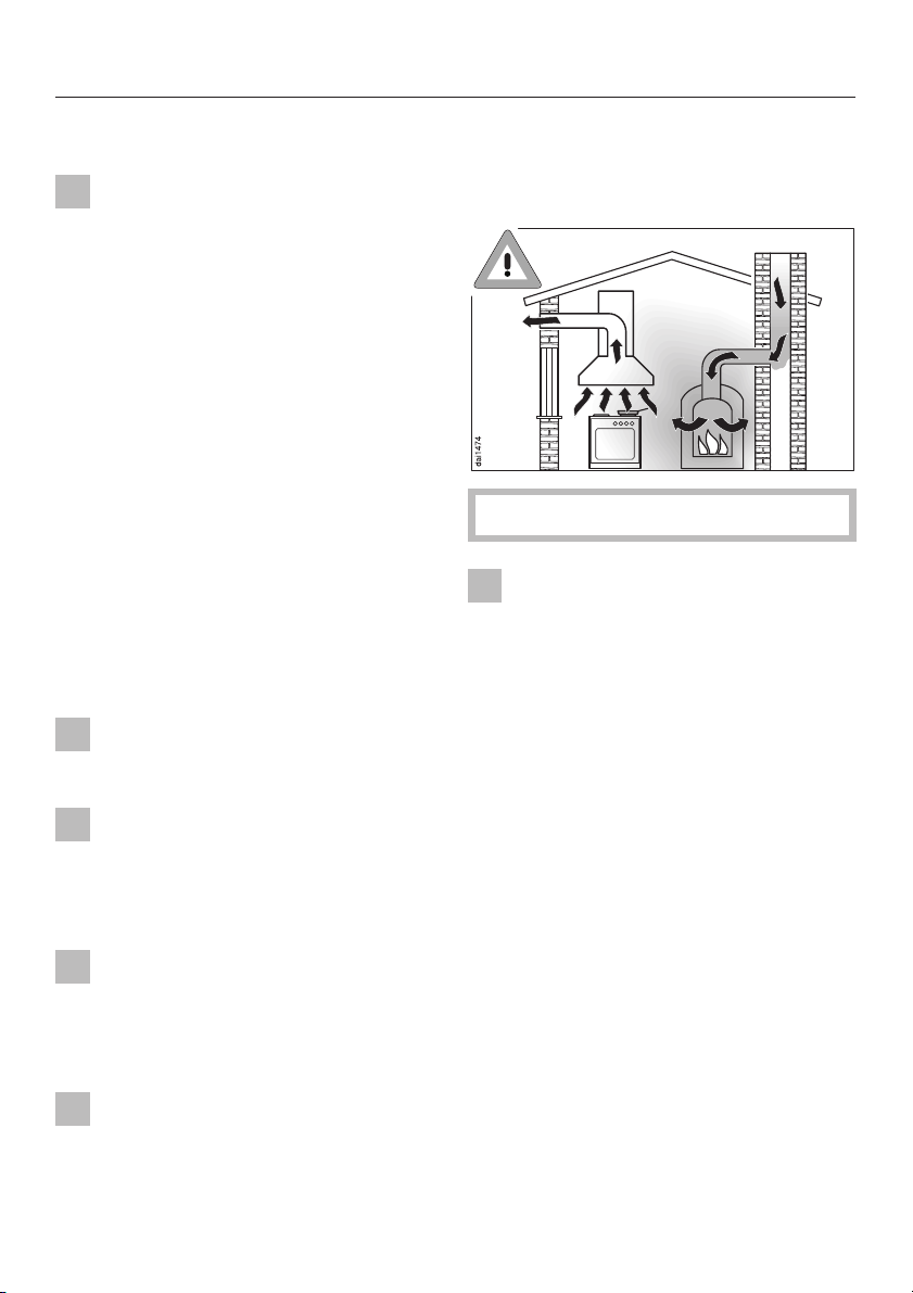
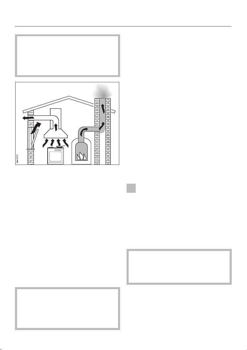
Using at the same time as other
heating appliances that depend on
the air from the room
Warning - danger of toxic fumes
Great care should be taken when
using the cooker hood at the same
time and in the same room or area of
the house as another heating appliance
which depends on the air in the room.
Such appliances include gas, oil, wood
or coal-fired boilers and heaters,
continuous flow or other water heaters,
gas hobs, cookers or ovens which draw
air in from the room and duct exhaust
gases out through a chimney or
extraction ducting.
When used in exraction mode and also
when an external motor is fitted, the
appliance draws air in from the room in
which it is installed and from
neighbouring rooms.
If there is insufficient air, an
underpressure will occur. The heating
appliance may be starved of oxygen,
impairing combustion.
6
Page 7
Warning and Safety instructions
Harmful gases such as carbon
monoxide could be drawn out of the
chimney or extraction ducting back
into the room with potentially fatal
consequences.
If adequate ventilation can only be
achieved through an open window, a
window contact switch must be fitted.
This ensures that the hood can only be
operated when the window is opened
wide enough.
The advice of a competent builder must
be sought. A window contact switch kit is
available from good builders' merchants.
Take care when ventilating the room
through an open window that ventilation
is not impaired by a closed blind or
curtain.
If the hood is being operated in
recirculation mode, the above
restrictions do not apply.
In order to ensure safe operation, and to
prevent gases given off by the heating
appliances from being drawn back into
the room when the extractor and the
heater are in operation simultaneously, an
underpressure in the room of 0.04 mbar
(4 pa) is the maximum permissible.
Ventilation can be maintained by air
inlets which cannot be blocked, in
windows, doors and outside wall vents,
or by other technical measures, such
as ensuring that the extractor can only
be switched on when the heating
appliance is switched off or vice-versa.
A ventilation brick alone is not generally
sufficient to ensure safe ventilation.
The overall ventilation condition of
the dwelling must be taken into
account. If in any doubt, the advice
of a competent builder or, for gas, a
"Corgi" installer, must be sought.
Disposal of your old appliance
Before discarding an old
appliance, switch off and
disconnect it from the power supply.
Cut off and render any plug useless.
Cut off the cable directly behind the
appliance to prevent misuse.
This should be done by a competent
person.
The manufacturer cannot be held
liable for damage caused by
non-compliance with these Warning
and Safety instructions.
7
Page 8
Description of the appliance
8
Page 9

Description of the appliance
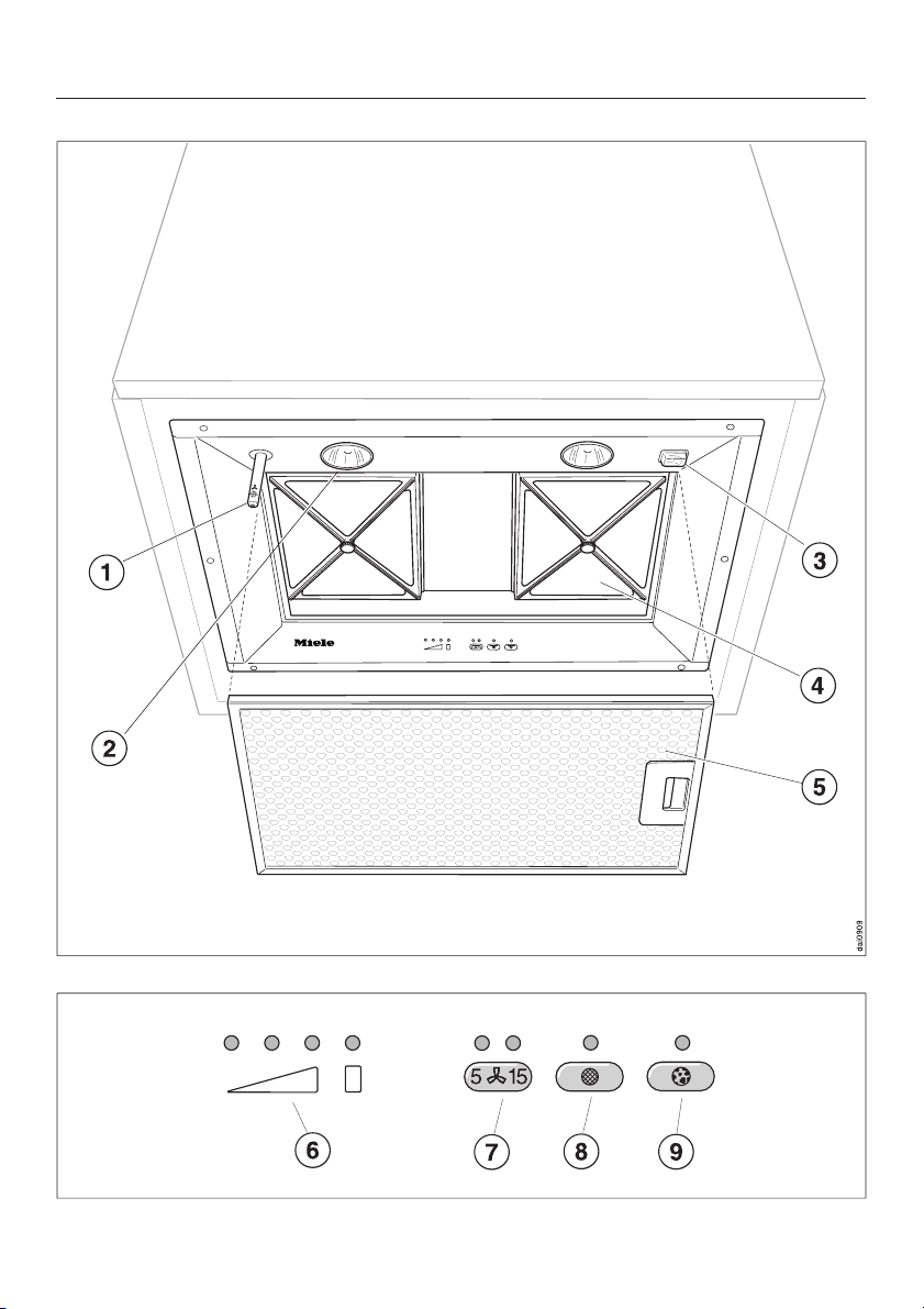
a Joystick
This is used to operate the fan
settings and the lighting.
b Hob lighting
c Master switch
d Charcoal filter
extra accessory available to order for
recirculation mode
e Grease filter
f Fan setting indicator lamps
g Touch control for the run-on
option
The fan can be set to continue
running for 5 or 15 minutes after
which the cooker hood will switch off
automatically.
h Touch control for the grease filter
The indicator lamp for the grease
filter touch control lights up when the
grease filter needs to be cleaned.
The touch control is used:
i Touch control for the charcoal
filters
The indicator lamp for the charcoal
filter touch control lights up when the
recirculation mode charcoal filters
need to be replaced.
The touch control is used:
to reset the operating hours counter
–
after replacing the charcoal filters
(see "Cleaning and care").
to show how long the charcoal filters
–
have been in use (see "Operation:
Filter operating hours counter").
– to alter the number of hours counted
by the filter operating hours counter
(see "Operation: Setting and altering
the charcoal filter operating hours
counter").
–
to reset the operating hours counter
after cleaning the grease filter (see
"Cleaning and Care").
–
to show how long the grease filter
has been in use (see "Operation:
Filter operating hours counter").
–
to alter the number of hours counted
by the filter operating hours counter
(see "Operation - To alter the grease
filter operating hours counter").
9
Page 10

Description of the functions
The cooker hood works with
. . . air extraction:
The air is drawn in and cleaned by the
grease filter and then directed outside.
If the on-site ventilation system does
not have a non-return flap, the
non-return flap supplied must be fitted.
The flap is closed when the cooker
hood is switched off. No exchange of
room and outside air can take place.
When the cooker hood is switched on,
the non-return flap opens for the
cooking vapours to be blown directly
outside.
. . . air recirculation:
(with air recirculation conversion kit as
an accessory)
The air is drawn in and cleaned first by
the grease filter and then cleaned by
charcoal filters. The cleaned air is then
recirculated back into the kitchen.
. . . an external motor:
(...EXT models only)
The ...EXT models are designed to be
connected to an external motor located
outside the room.
The external motor is connected to the
cooker hood by means of a control
cable, and is operated by the controls
on the cooker hood.
Before using the cooker hood in
recirculation mode, ensure that the
charcoal filters are in place, see
"Cleaning and care".
10
Page 11
Operation
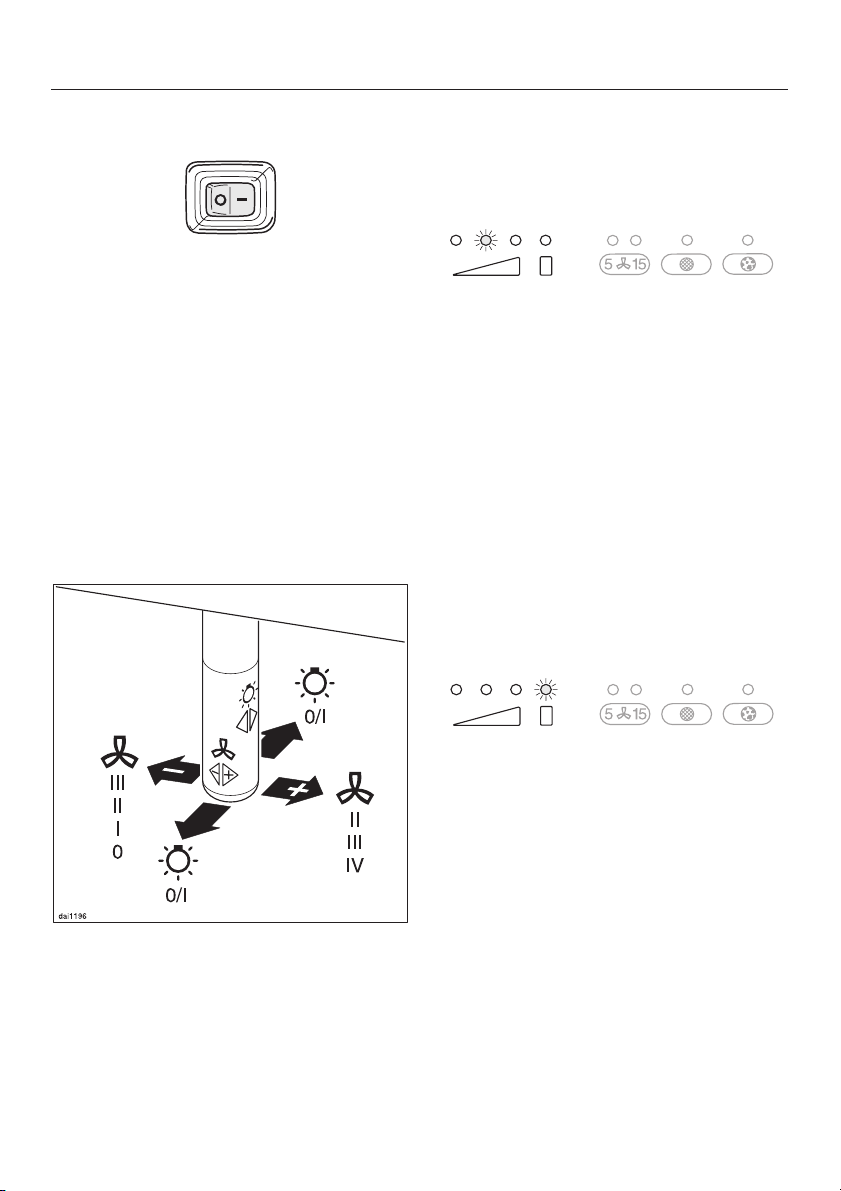
Master switch
Switch the master switch to the on
position "–". The fan and the lighting
can now be operated.
If the appliance is not going to be used
for a longer period of time (e.g. whilst
on holiday) switch the appliance off by
switching the master switch to "0".
The next time it is switched on the
cooker hood will operate at the level
previously used.
Joystick
To switch the fan on
Press the joystick once to the right.
^
The fan will come on at power level "lI".
The second fan setting indicator will
light up.
To select a power level
Press the joystick repeatedly to the
^
right to select a higher power level, and
to the left to select a lower power level.
The relevant fan setting indicator will
light up.
Depending on the intensity of cooking
vapours, levels "I" to "III" (green
indicator lamps) are usually sufficient
for normal cooking.
This is used to operate the fan settings
and the lighting.
For short periods of intensive cooking
vapours, e.g. when searing meat, you
may wish to select the Intensive setting
(yellow indicator lamp).
To switch the fan off
^
Press the joystick repeatedly to the
left until the fan switches off and the
fan setting indicator lights have all
gone out.
or
^
Press and hold the joystick to the left.
The fan setting indicator lamps will
go out.
11
Page 12
Operation
Hob lighting
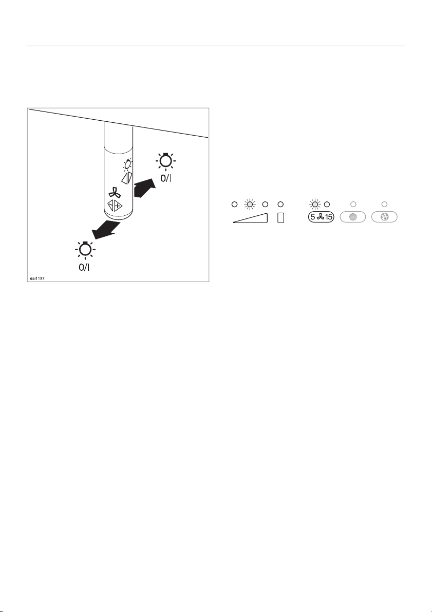
The hob lighting can be switched on
and off independently of the fan.
^ Press the joystick once to the rear or
to the front to switch it on.
^ Press the joystick again once to the
rear or to the front to switch it off.
Run-on option
It is advisable to run the fan for a few
minutes after cooking is finished to
neutralise any lingering odours in the
air, whether you are using air extraction
or recirculation mode.
The fan can be set to switch off
automatically after either 5 or 15
minutes:
^ After cooking is finished, press the
run-on option touch control whilst the
fan is still running.
– Press once = The fan switches off
after 5 minutes (left-hand indicator
lamp).
– Press twice = The fan switches off
after 15 minutes (right-hand indicator
lamp).
Safety cut-out
Should the cooker hood be left on, the
fan will switch off automatically after 10
hours. The lighting will remain on.
^
Pressing the joystick once to the right
will switch the fan back on again.
12
To switch off the run-on option, press
the run-on option touch contol again.
The cooker hood then has to be
switched off manually.
Page 13
Operation
Filter operating hours counter
The number of hours the appliance has
been in operation is stored in memory.
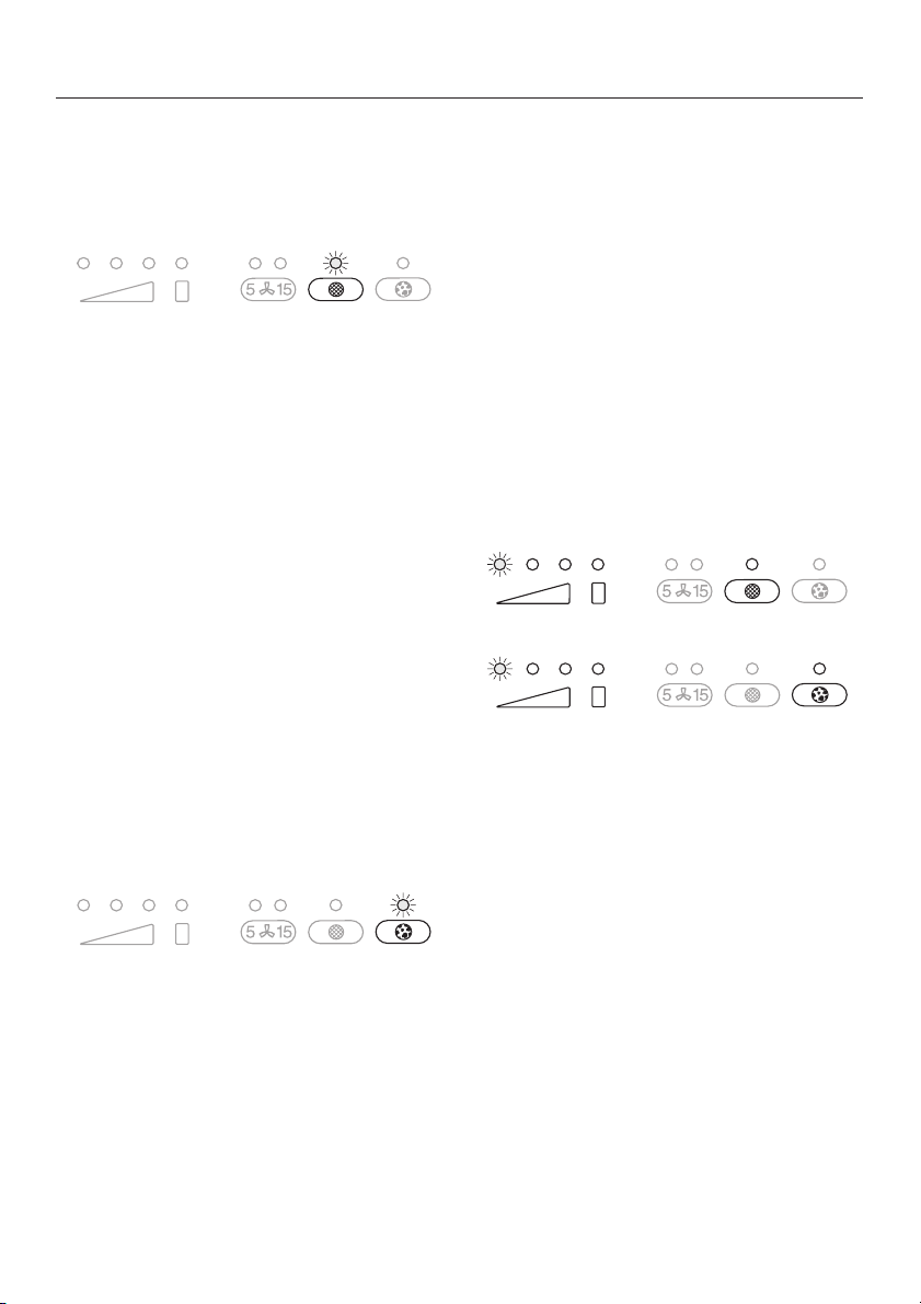
The indicator lamp for the grease filter
touch control will come on after 30
hours of operation. The grease filter
must then be cleaned.
After the grease filter has been cleaned
and put in place, the filter operating
hours counter must be re-set.
^ To do this, press the grease filter
touch control and hold for about 3
seconds.
The indicator lamp for the touch control
will go out.
For information on how to change the
operating hours counter see "Setting
and altering the grease filter operating
hours counter".
With recirculation mode:
After the new charcoal filters have been
put in place, the filter operating hours
counter must be re-set.
Press the charcoal filter touch control
^
for about 3 seconds.
The indicator lamp for the touch control
will go out.
Reading the filter operating hours
counter
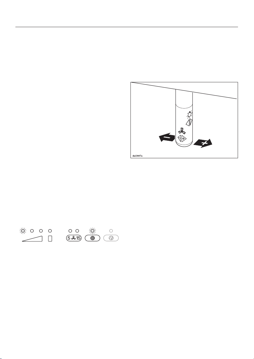
To check the percentage of time set
already used:
Switch the fan on with the joystick.
^
^ Press the grease filter or the charcoal
filter touch control.
One or several of the power level touch
control lamps will flash.
The charcoal filter indicator lamp will
light up after the cooker hood has
operated for the number of hours set
(see "Setting and altering the charcoal
filter operating hours counter"). The
charcoal filters must then be replaced
with new ones.
The number of flashing lights shows the
percentage of the operating time which
has already been used up.
1 lamp = 25 %
2 lamps = 50 %
3 lamps = 75 %
4 lamps = 100 %
The number of operating hours used
remains in the memory, even when the
appliance is switched off or there is a
power cut.
13
Page 14
Operation
Setting and altering the operating
hours counter
You can set the operating hours
counter to suit the type of cooking you
do.
Select a short time if you roast or fry
–
a lot.
If you use very little fat for cooking,
–
select a longer time.
If you only cook occasionally we
–
recommend that you still select a
short time, because grease which
has built up gradually over a long
period of time will harden on the
grease filter and make cleaning more
difficult.
To alter the grease filter operating
hours counter
The operating hours counter for the
grease filter is set to 30 hours. The time
set can be lengthened or shortened:
you can choose 20, 30, 40 or 50 hours.
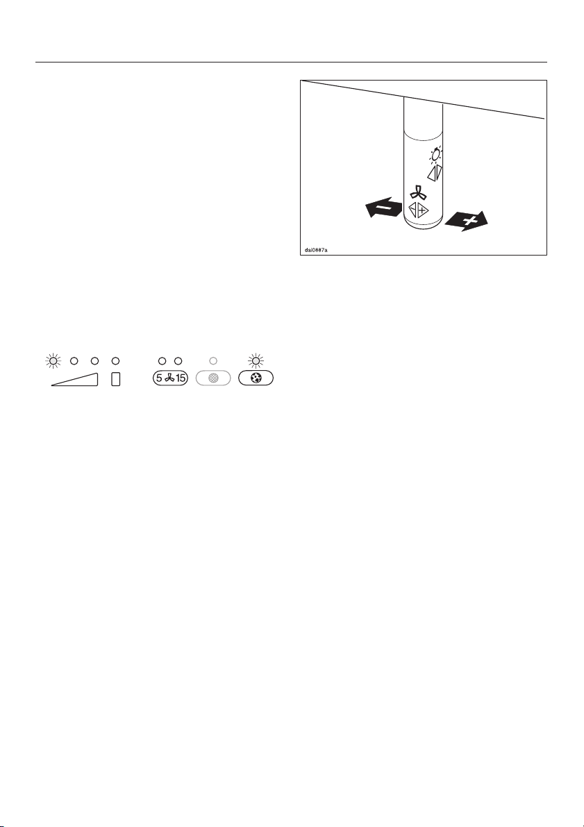
The power level touch control lamps
show the time which has been set:
1st lamp from the left = 20 hours
2nd lamp from the left = 30 hours
3rd lamp from the left = 40 hours
4th lamp from the left = 50 hours
^ Use the joystick to select the time
required.
Press to the left for a shorter
operating time, or to the right for a
longer time.
^ Confirm the selection by pressing the
grease filter touch control.
^
Switch the fan on with the joystick.
^
Press the run-on option touch control
and the grease filter touch control at
the same time.
The indicator lamp for the grease filter
touch control and one of the lamps for
the power level touch controls will flash.
14
All the indicator lamps will go out.
If the procedure is not confirmed within
4 minutes of programming the steps,
the cooker hood will automatically
revert to the "old" data.
Page 15
Setting and altering the charcoal
filter operating hours counter
(with recirculation mode)
The charcoal filters must be fitted for
the cooker hood to be used in
recirculation mode.
On delivery, the operating hours
counter for the charcoal filters is set to
unlimited.
Operation
For recirculation mode, the operating
hours counter needs to be set to the
required time:
Switch the fan on with the joystick.
^
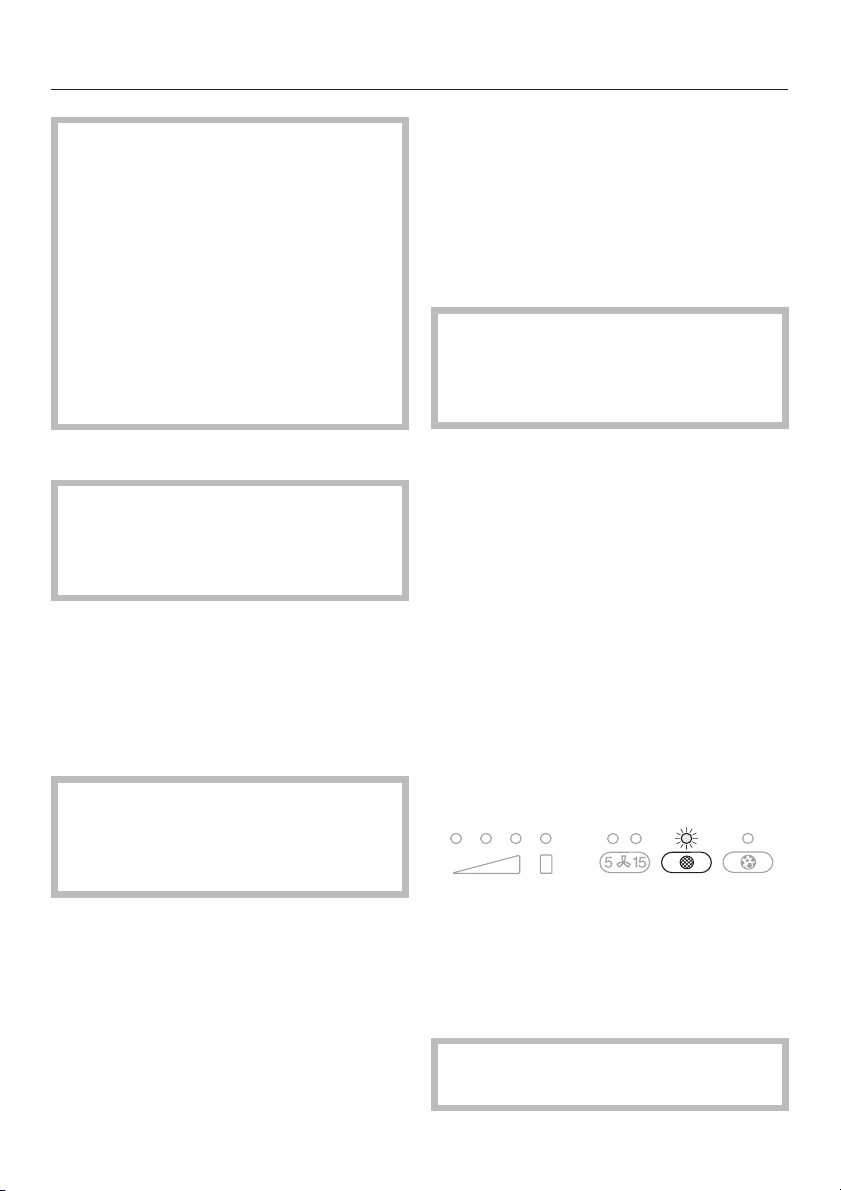
^ Press the run-on option touch control
and the charcoal filter touch control
at the same time.
The indicator lamp for the charcoal filter
touch control and one of the power
level touch control lamps will flash.
The power level touch control lamps
show the time which has been set:
1st lamp from the left = 120 hours
2nd lamp from the left = 180 hours
3rd lamp from the left = 240 hours
4th lamp from the left = unlimited
Use the joystick to select the time
^
required.
Press to the left for a shorter
operating time, or to the right for a
longer time.
^ Confirm the procedure by pressing
the charcoal filter touch control.
All the indicator lamps will go out.
If the procedure is not confirmed within
4 minutes of programming the steps,
the cooker hood will automatically
revert to the "old" data.
15
Page 16
Cleaning and care
Before any cleaning or maintenance
work is carried out, disconnect the
cooker hood from the mains supply.
Ensure that
- it is switched off at the wall socket
and the plug is withdrawn, or
- or the fuse is withdrawn from the
fused spur connection unit, or
- the mains fuse is withdrawn,or
- or the screw-out fuse is removed
(in countries where this is
applicable)
abrasive cleaning agents, e.g.
–
powder cleaners or cream cleaners
and abrasive sponges, as well as pot
scourers or sponges which have
been used previously with abrasive
cleaning agents.
These will damage the surface
material.
The controls may suffer
discolouration or damage if soiling is
left on them for too long.
Remove any soiling straight away.
Housing
The surfaces and controls are
susceptible to scratches and
abrasions. Please observe the
following cleaning instructions.
^ All external surfaces and controls can
be cleaned using warm water with a
little washing-up liquid applied with a
well wrung-out soft sponge or cloth.
^
Wipe the surfaces dry using a soft
cloth.
Do not use too much water when
cleaning the controls. Water could
penetrate into the electronics and
cause damage.
Avoid:
–
cleaning agents containing soda,
acids, chlorides or solvents,
E-Cloth
^ A microfibre "E-Cloth" is available
from the Miele UK Spare Parts
Department which is suitable for
cleaning surfaces such as stainless
steel, glass, plastic and chrome
without the use of chemicals.
Grease filter
The re-usable metal grease filter in the
appliance removes solid particles from
the kitchen vapours (grease, dust, etc)
preventing soiling of the cooker hood.
The grease filter should be cleaned
regularly (at least every 3-4 weeks) to
avoid a built-up of fat but always clean
immediately the grease filter touch
control lamp comes on.
16
An oversaturated filter is a fire
hazard.
Page 17
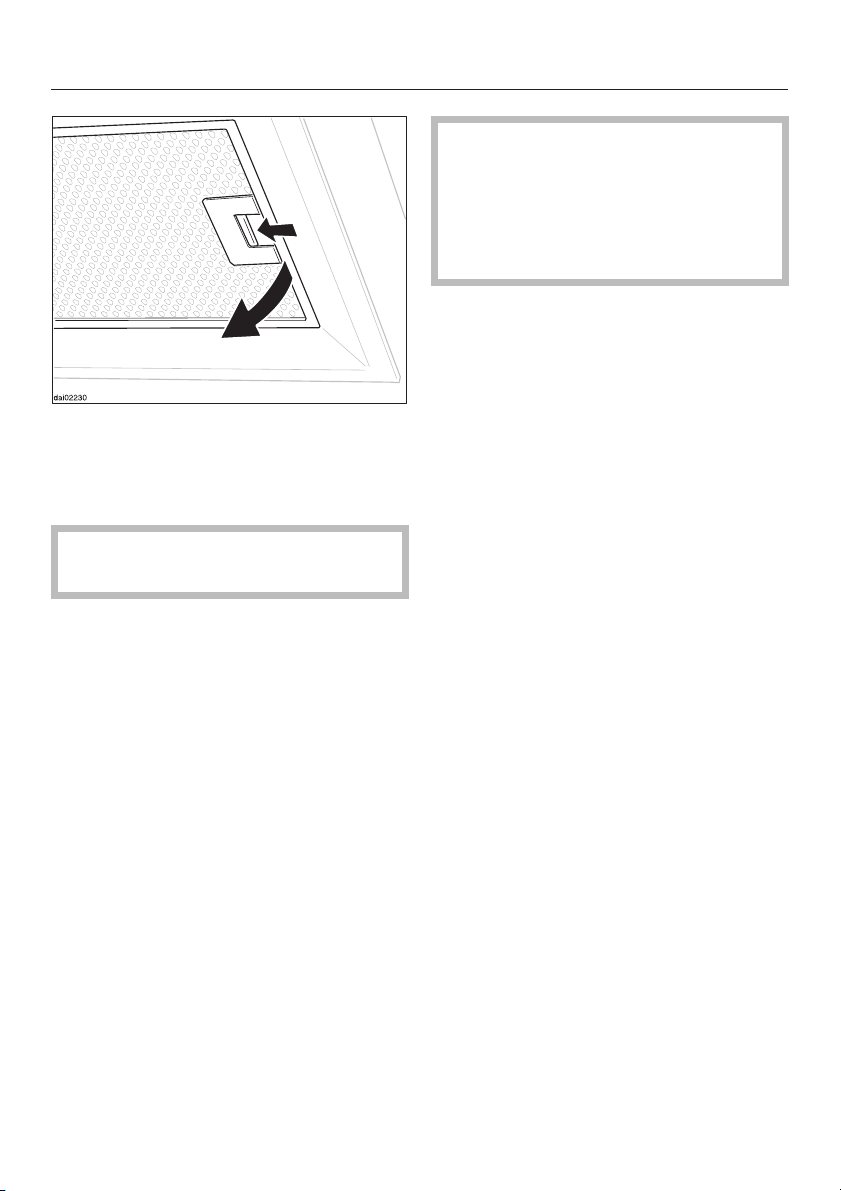
To take out the grease filter, press the
^
locking clip in towards the middle of
the filter. Holding carefully, lower and
remove the filter.
Take care not to let the grease filter
fall onto the hob below.
^ Clean the filter
- by hand: with a soft nylon brush,
hot water and a little washing up
liquid.
- in a dishwasher: place the filter
upright in the lower basket and select
a 65°C programme.
The filter can be placed diagonally if
this is easier. If necessary, raise the
height of the upper basket.
Ensure the spray arm is not
obstructed.
Cleaning and care
Depending on the cleaning agent
used, cleaning the grease filter in a
dishwasher can cause permanent
discolouration to the surface.
However, this will not affect the
functioning of the filter in any way.
After cleaning, leave the filter to dry
^
for a while on an absorbent surface
before putting it back in place.
When removing the filter for cleaning
^
also clean off any residues of oil or fat
from the now accessible housing to
prevent the risk of these catching fire.
When putting the grease filter back in
position, ensure that the locking clip is
visible facing down towards the hob.
Should the filter be replaced upside
down, insert a small screwdriver blade
into the slit to disengage the clip. Do
not let the filter drop on to the hob
below.
^ After replacing the grease filter, press
the grease filter touch control for
approx. 3 seconds to re-set the
operating hours counter.
The indicator lamp will go out.
^
If the grease filter is cleaned before
the operating hours counter has
reached its maximum, the grease
filter touch control should be pressed
for approx. 6 seconds to reset the
counter.
17
Page 18
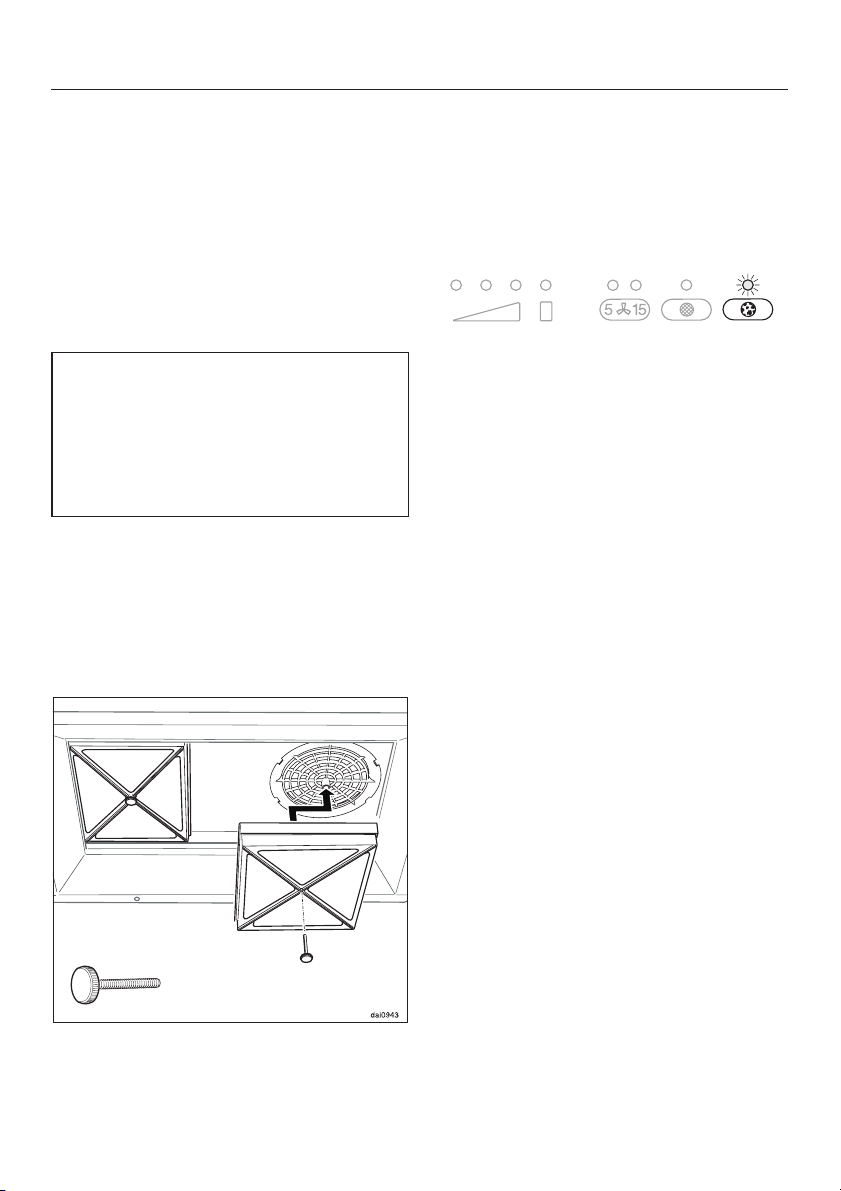
Cleaning and care
Fitting and replacing the
charcoal filter
If the cooker hood is connected for
recirculation, two charcoal filters must
be inserted in addition to the grease
filter. Charcoal filters absorb normal
kitchen odours.
They are fitted in the canopy above the
grease filter.
Charcoal filters can be obtained from
your dealer or the Miele Spare Parts
Department.
See back cover for contact details,
and "Technical data" for type and
reference number.
^ Before fitting or replacing the
charcoal filters, the grease filter must
first be taken out, (see previous
section for instructions on how to do
this).
^ Unwrap the charcoal filters.
When fitting for the first time:
Set the operating hours counter to
^
suit your requirements, (see
"Operation - Filter operating hours
counter").
Always replace the filters immediately if
the lamp for the charcoal filter touch
control comes on, or if they are no
longer effective in absorbing kitchen
odours.
They should, however, be replaced at
least every 6 months.
^ After fitting a new charcoal filter,
press the charcoal filter touch control
for approx. 3 seconds to re-set the
operating hours counter.
The indicator lamp will go out.
^ If the charcoal filters are replaced
before the operating hours counter
has reached its maximum, the
charcoal filter touch control should be
pressed for approx. 6 seconds to
reset the counter.
^
Remove the old filters and replace
with the new ones as illustrated.
^
Replace the grease filter.
18
Page 19
Changing a lamp
Disconnect the cooker hood from
the mains electricity supply. Ensure
that:
– it is switched off at the wall socket
and the plug has been withdrawn
or
– the fuse has been withdrawn from
the fused spur connection unit, or
– the mains fuse is withdrawn, or
– the screw-out fuse is removed (in
countries where this is applicable).
Ensure that current is not supplied to
the appliance until after maintenance
or repair work has been carried out.
Exercise caution when changing
halogen lamps. They get very hot
during use and remain hot for some
time after being switched off. Please
follow the manufacturer's instructions.
Cleaning and care
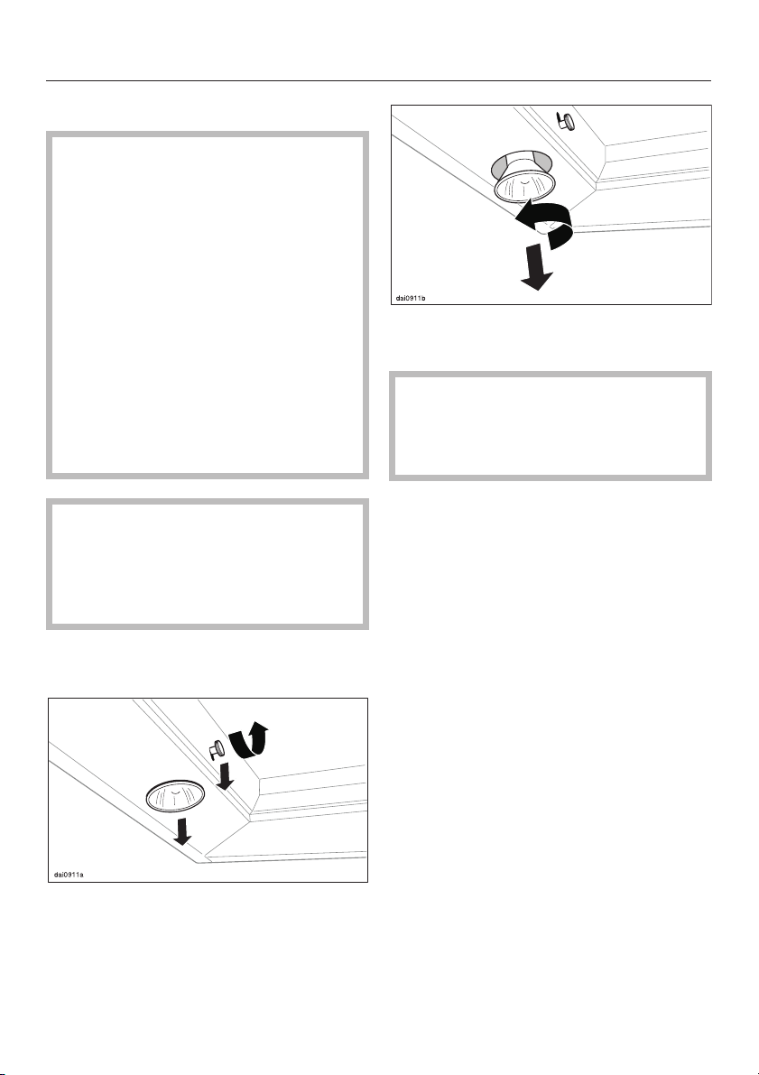
Turn the halogen lamp anti-clockwise
^
and pull it downwards to remove.
We recommend replacing the lamp
with the same type :
PHILIPS Halotone GZ 10, 230V,
50 W, 50°, Type. 14560.
^ Fit the new halogen lamp by
reversing the above procedure.
^ Replace the grease filter.
^
Remove the grease filter from the
cooker hood.
^
Loosen the halogen lamp securing
screw slightly and push downwards
(see illustration).
^
Tighten up the screw again.
19
Page 20
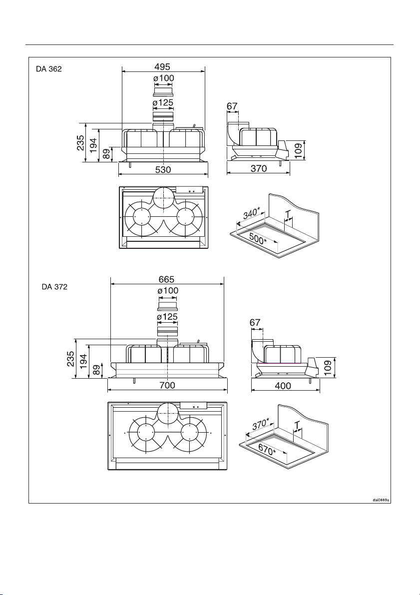
Appliance dimensions
*Cut-out dimensions A depth T of at least 40 mm must be
provided at the back of the building in
niche.
20
Page 21
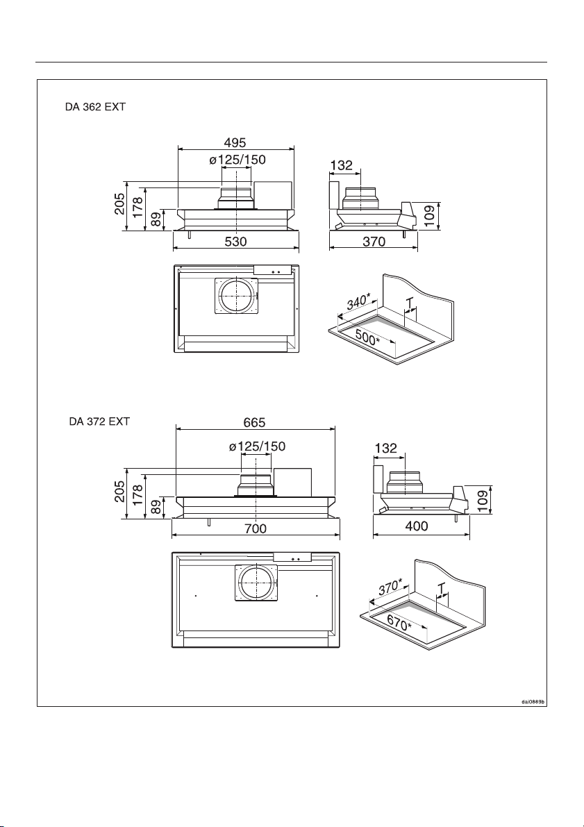
Appliance dimensions
*Cut-out dimensions A depth T of at least 40 mm must be
provided at the back of the building in
niche.
21
Page 22
Installation
Safety regulations prohibit the fitting
of this cooker hood above a solid
fuel stove.
For safety reasons the minimum
safety distance between the top of
the cooker/hob and the bottom of
the cooker hood should be at least:
– 450 mm above electric hobs
and cookers.
– 650 mm above gas hobs and
cookers
– 650 mm above an open grill
from our range.
See “Warning and Safety
instructions” for further information.
A distance of 650 mm above electric
cookers/hobs may be preferable to give
more working space.
Fitting the non-return flap
(Air extraction mode only,
not for operation with an external motor)
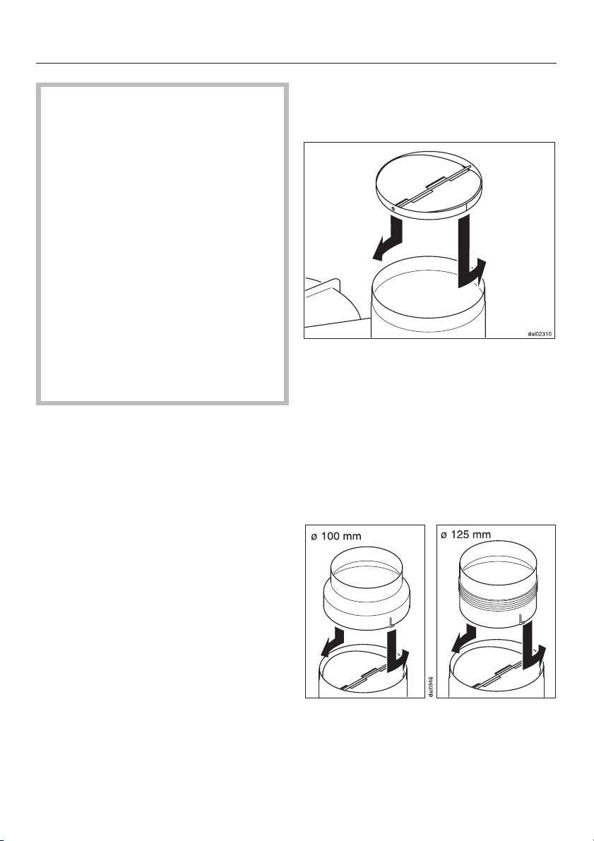
^ If a non-return valve is not present in
the venting system, the non-return
flap supplied must be fitted onto the
exhaust stub in the motor unit. The
flaps must open upwards.
^ Turn the non-return flap slightly
anti-clockwise to secure it.
22
Exhaust connection
^
A C 100 mm or C 125 mm adapter
must be fitted to the exhaust stub to
suit the exhaust ducting being used.
Turn it slightly anti-clockwise to secure
it (not for use with an external motor).
Page 23
Operation with an external motor (...EXT
models)
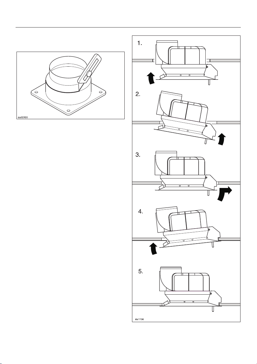
If a C 150 mm exhaust ducting has to
^
be used, adapt the stub by cutting it
off at the join with a sharp knife (see
illustration).
The exhaust stub does not need to
be adapted if C 125 mm ducting is
being used.
It has an integrated non-return flap.
Building in
Installation
The cooker hood is intended to be
built-into wall units, cooker hood
housing units, and above breakfast
bars or island areas.
Check prior to installation that the top of
the appliance will be accessible after
installation.
If this is not the case, install the exhaust
ducting and prepare the electrical
connection and the connection to the
external motor (...EXT models only)
before installation.
^
Place the appliance, as illustrated, in
the cut-out from below and align it.
23
Page 24
Installation
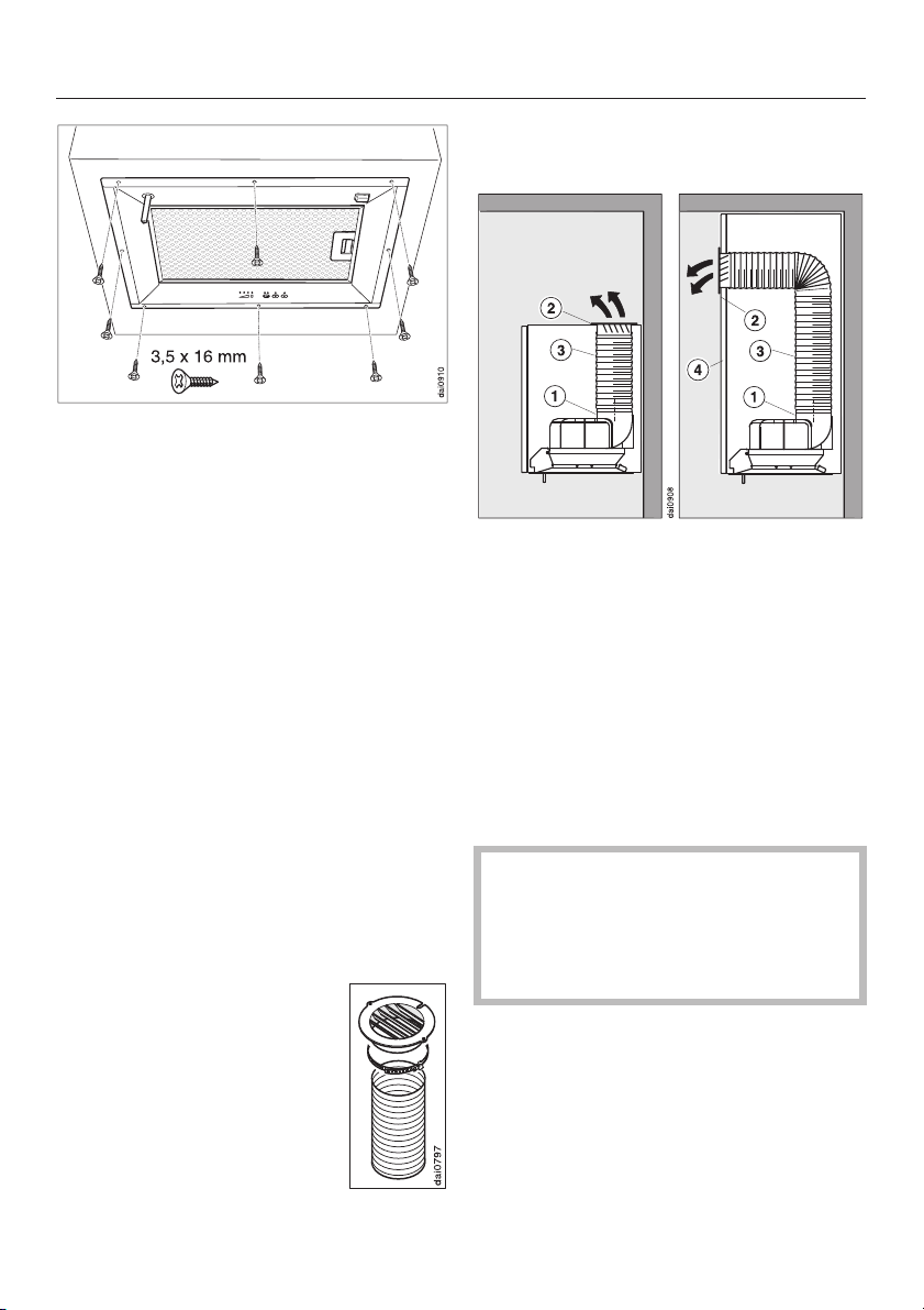
Secure the cooker hood to the frame
^
using 3.5 x 16 mm screws.
Preparation for extraction
^ Secure the vent ducting to the
exhaust stub with a hose clip and
connect to the venting system (see
"Connection for air extraction").
Preparation for recirculation
If site conditions are not suitable for the
cooker hood to be used for air
extraction, the appliance must be
connected for recirculation.
The following parts, available through
your dealer or from the Miele Spare
Parts Department are required for
operating the appliance in recirculation
mode:
–
Conversion kit for
recirculation mode
(C 125 mm):
Exhaust grille, ducting,
hose clip
Connection for recirculation
mode
^ When fitting the cooker hood in a wall
unit the exhaust grille b has to be
fitted in the top of the wall unit.
^ The exhaust stub a and the exhaust
grille b are joined together using a
suitable hose or flexible ducting c. If
the front of the unit is ceiling height
(i.e. extractor canopies, ceiling
mounted units) then an appropriate
cut-out must be made in the front
panel d.
When fitting the exhaust grille make
sure that the slats in the grille point
towards the centre of the room and
not directly towards a wall or the
ceiling.
^
Install the charcoal filters (see
"Cleaning and care").
–
2 charcoal filters (see
“Technical data”)
24
Page 25
Installation
Fitting the joystick
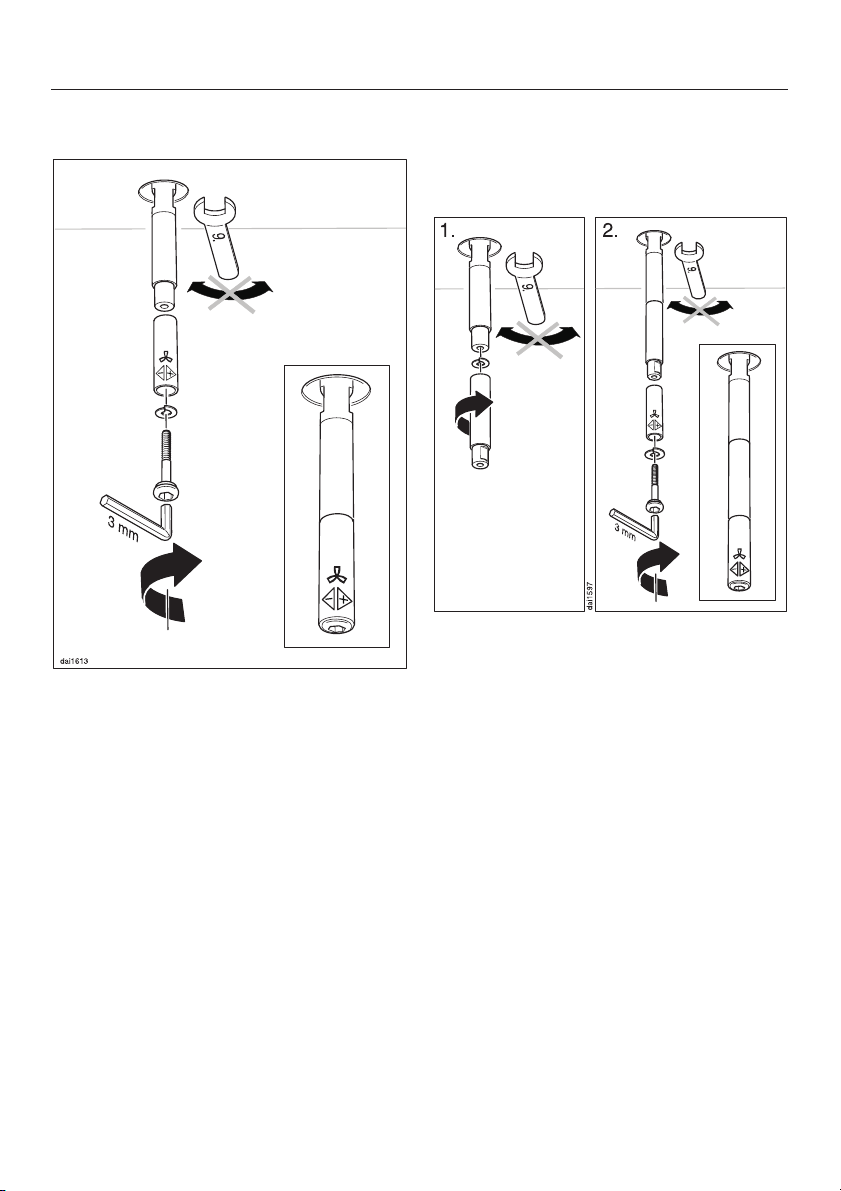
^ Fit the lower section of the joystick
onto the stub and lightly secure in
position with the screw supplied and
a spring washer. Do not tighten the
screw yet!
^
Turn the lower section around, until
the m symbol is facing the front.
Joystick extension
The joystick can be extended if
required.
^ Whilst counterholding the base of the
joystick with an SW 9 spanner (do not
turn), secure the joystick extension to
the stub using a spring washer in
between them, as shown above.
^
Then attach the lower section of the
joystick as previously described, turn
the m symbol to the front and then
tighten the screw up.
^
Then tighten the screw with a 3 mm
allen key. Whilst doing so counterhold
the base of the joystick with an SW 9
spanner, but do not turn.
25
Page 26
Installation
Electrical connection
If the cooker hood is to be connected
^
to an external motor (...EXT models):
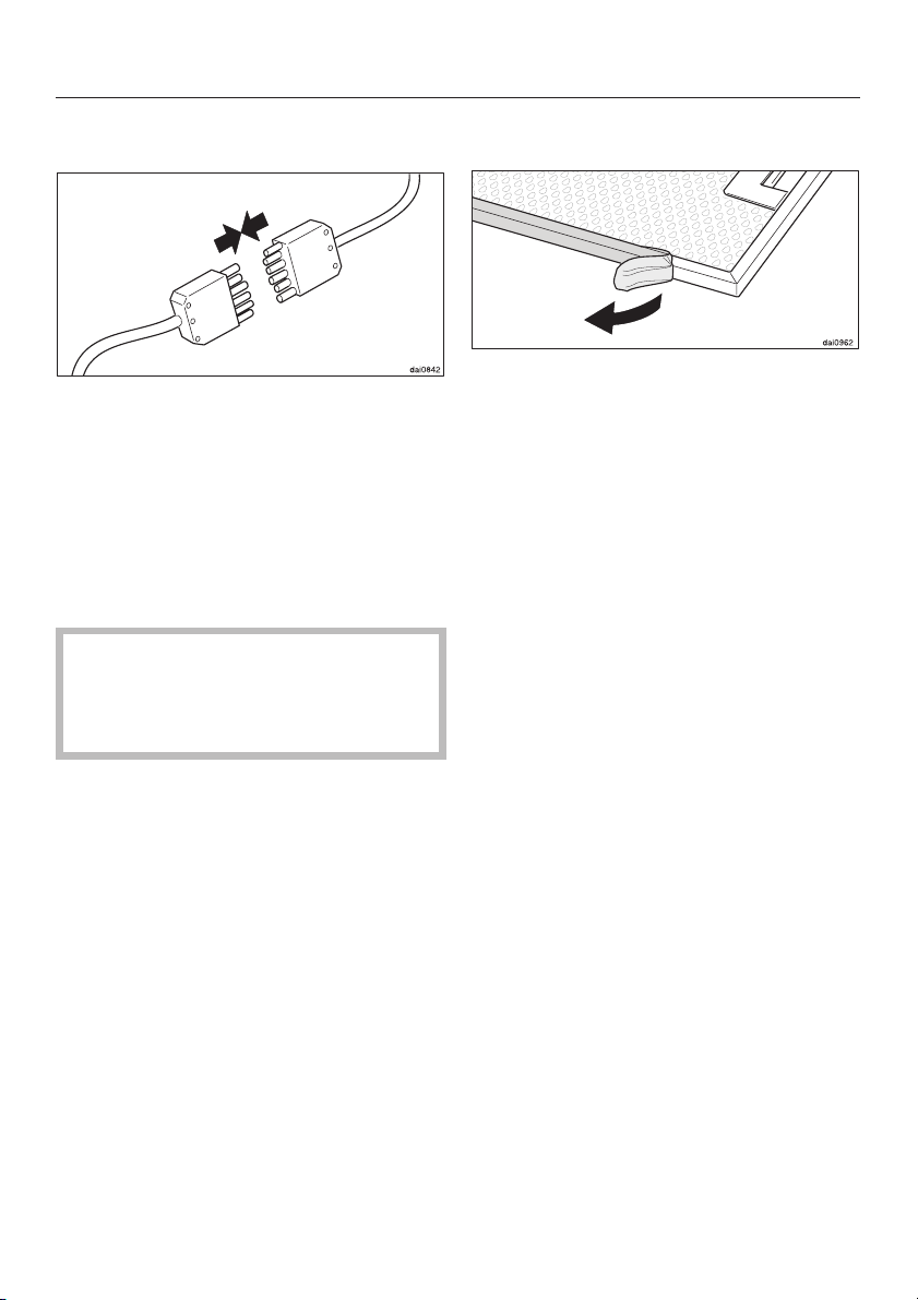
Use the connection cable with 6 pole
plug to connect the cooker hood and
the external motor.
^ Connect the appliance to the mains
via a fused spur or fused socket as
appropriate.
Before connecting the appliance
read the safety notes in “Warning
and Safety instructions” and
“Electrical connection”.
Before using the appliance for the
^
first time, take the grease filter out
and remove the protective foil from
the filter frame. Then replace the
grease filter.
26
Page 27
Danger of toxic fumes.
Please heed the "Warning and
Safety instructions" to avoid the
danger of toxic fumes.
The cooker hood should be installed
according to local building
regulations. Seek approval from the
building inspector where necessary.
All ducting, pipework and fittings
–
must be of non-flammable material.
The extraction ducting should be as
–
short and straight as possible.
– To ensure efficient air extraction the
diameter of the exhaust ducting
should not be less than 125 mm.
If exhaust ducting with a diameter of
less than 125 mm or flat ducting
were to be used the noise level of
the cooker hood would increase and
extraction would be less efficient.
Connection for air extraction
Where ducting is horizontal it must
–
be laid to slope away at at least 1 cm
per metre.
This is to ensure that condensate
cannot drain back into the cooker
hood.
If the exhaust air is to be ducted into
–
the open air, the installation of a
telescopic wall vent is recommended.
Only reduce the diameter of the
ducting if absolutely necessary, e.g.
where narrower ducting has already
been installed.
–
Only use wide radius bends. Tight
bends reduce the air throughput of
the cooker hood.
–
Only use smooth pipes or flexible
hoses made from non-flammable
materials for extraction connection.
–
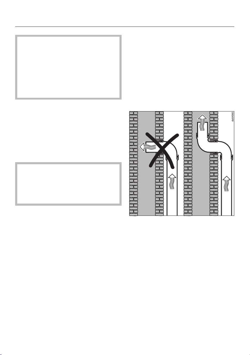
If the exhaust air is to be ducted into
a vent flue, the ducting must be
directed in the flow direction of the
flue.
27
Page 28
Connection for air extraction
Important:
If the exhaust ducting is to run through
rooms, ceiling space etc. where there
may be great variations in temperature
between the different areas, the
problem of sweating or condensation
will need to be addressed. The exhaust
ducting will need to be suitably
insulated.
Condensate trap
In addition to insulating the exhaust
ducting we recommend that a suitable
condensate trap is also installed to
collect and evaporate any condensate
which may occur.
When installing a condensate trap
ensure that it is positioned vertically
and if possible directly above the
exhaust connection.
28
Page 29
All electrical work should be
undertaken by a suitably qualified
and competent person in strict
accordance with national and local
safety regulations.
Installation, repairs and other work
by unqualified persons could be
dangerous, for which the
manufacturer cannot be held liable.
Ensure power is not supplied to the
appliance until after installation or
repair work has been carried out.
Do not connect the appliance to the
mains electricity supply by an
extension lead. These do not
guarantee the required safety of the
appliance.
The voltage and connected load are
given on the data plate. This is visible
when the grease filters have been
removed. Ensure that these match the
household mains supply.
Electrical connection
For extra safety it is advisable to install
a residual current device (RCD) with a
trip current of 30 mA.
Important
U.K., IRL, NZ, ZA: This appliance is
supplied for connection to an a.c.
230 V single phase 50 Hz supply.
AUS: This appliance is supplied for
connection to an a.c. single phase
240 V, 50 Hz supply.
The wires in the mains lead are
coloured in accordance with the
following code:
Green/yellow = earth
Blue = neutral
Brown = live
WARNING:
THIS APPLIANCE MUST BE
EARTHED
Connection of this appliance should be
made via a suitable isolator or a double
pole fused spur connection unit which
complies with national and local safety
regulations and the On-Off switch
should be easily accessible after the
appliance has been built in.
When switched off there must be an
all-pole contact gap of 3 mm in the
switch (including switch, fuses and
relays according to EN 60 335).
If the switch is not accessible after
installation (depending on country), an
additional means of disconnection must
be provided for all poles.
29
Page 30
After Sales Service
In the event of a fault which you cannot
correct yourself, or if the appliance is
under guarantee, please contact:
Your Miele Dealer
–
or
The Service Department (see back
–
cover for address).
When contacting your Dealer or the
Service Department, please quote the
model and serial number of your
appliance. These are shown on the
data plate which is visible when the
grease filter is removed.
Please note that telephone calls may
be monitored and recorded to
improve our service.
30
Page 31

Technical data
Connected load
DA 362, DA 372. . . . . . . . . . . . . . 320 W
Fan. . . . . . . . . . . . . . . . . . . . 2 x 110 W
Lighting . . . . . . . . . . . . . . . . . 2 x 50 W
Voltage . . . . . . . . . . . . . . . . . . AC 230 V
Frequency. . . . . . . . . . . . . . . . . ~ 50 Hz
Fuse rating (UK). . . . . . . . . . . . . . . 13 A
Electrical cable length . . . . . . . . . 1.5 m
Fan performance
Extraction power according to
EN 61591
Extraction system C 125 mm:
Level I . . . . . . . . . . . . . . . . . . . 220 m
Level II. . . . . . . . . . . . . . . . . . . 350 m
Level III . . . . . . . . . . . . . . . . . . 450 m
Intensive level . . . . . . . . . . . . . 560 m
3
/h
3
/h
3
/h
3
/h
Extraction system C 100 mm:
Level I . . . . . . . . . . . . . . . . . . . 200 m
Level II. . . . . . . . . . . . . . . . . . . 330 m
Level III . . . . . . . . . . . . . . . . . . 380 m
Intensive level . . . . . . . . . . . . . 440 m
Unrestricted. . . . . . . . . . . . . . . 650 m
3
/h
3
/h
3
/h
3
/h
3
/h
For ...EXT models the connected load
and extraction power will depend on
the type of motor fitted.
Length of connection cable to external
motor. . . . . . . . . . . . . . . . . . . . . . . 1.9 m
Recirculation with charcoal filter:
Level I . . . . . . . . . . . . . . . . . . 160 m
Level II . . . . . . . . . . . . . . . . . 240 m
Level III . . . . . . . . . . . . . . . . . 300 m
Intensive level . . . . . . . . . . . . 360 m
* Depending on installation
Miele Active charcoal filter DKF 2
3
3
3
3
/h *
/h *
/h *
/h *
31
Page 32

Alteration rights reserved / 4804
M.-Nr. 05 889 281 / 04
en-GB
 Loading...