

mie cctv H.264 Digital Video Recorder User Manual
DVR User guide
- 1 -
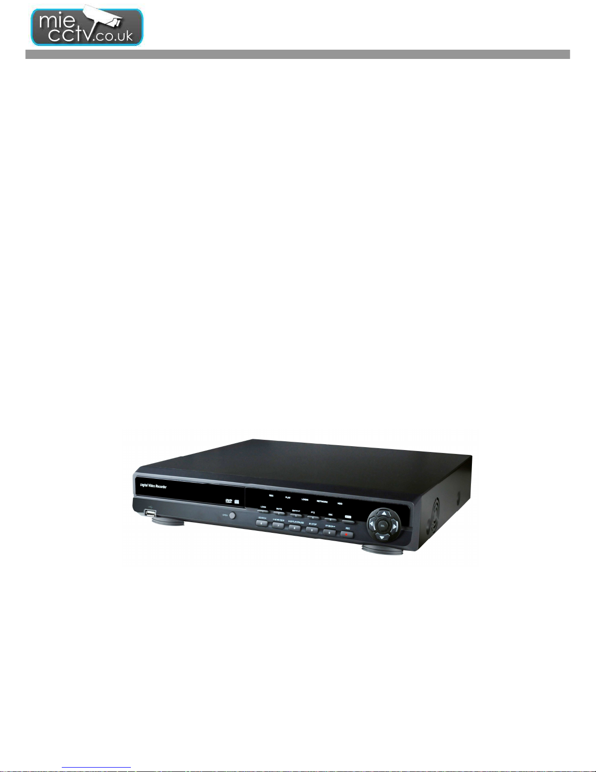
USER GUIDE
H.264 Digital Video Recorder
V1.0
This document contains preliminary information and subject to change without notice
DVR User guide
- 2 -
SAFETY PRECAUTIONS
This symbol is intended to alert
the user to the presence of
unprotected “Dangerous voltage"
within the product's enclosure
that may be strong enough to
cause a risk of electric shock.
This symbol is intended to alert
the user to the presence of
important operating and
maintenance (servicing)
instructions in the literature
accompanying the appliance.
WARNING
TO REDUCE THE RISK OF FIRE OR ELECTRIC
SHOCK, DO NOT EXPOSE THIS APPLIANCE
TO RAIN OR MOISTURE.
NOTE: This equipment has been tested and
found to comply with the limits for a class digital
device, pursuant to part 15 of the FCC Rules.
These limits are designed to provide reasonable
protection against harmful interference when the
equipment is operated in a commercial
environment. This equipment generates, uses,
and can radiate radio frequency energy and, if not
installed and used in accordance with the
instruction manual, may cause harmful
interference to radio communications. Operation
of this equipment in a residential area is likely to
cause harmful interference in which case the user
will be required to correct the interference at his
own expense.

DVR User guide
- 3 -
Table of Contents
1. PACKING LIST............................................................................................................... 5
2. PANEL LOCATION........................................................................................................ 6
2-1 FRONT PANEL CONTROLS ............................................................................................................................................. 6
2-2 16CH REAR PANEL CONNECTORS ................................................................................................................................ 7
2-3 8CH REAR PANEL CONNECTORS .................................................................................................................................. 8
2-4 4CH REAR PANEL CONNECTORS .................................................................................................................................. 9
3. Product Specification ........................................................ Error! Bookmark not defined.
4. LIVE, PLAYBACK AND PTZ OPERATIONS.......................................................... 11
4-1 LIVE Mode ........................................................................................................................................................................ 11
4-2 PLAYBACK Mode ............................................................................................................................................................ 16
4-3 PTZ Mode .......................................................................................................................................................................... 18
5. MAIN MENU SETUP ................................................................................................... 20
5-1 RECORD SETUP .............................................................................................................................................................. 22
5-1.1 Quality & Frame Rate Setup ....................................................................................................................................... 23
5-2 EVENT SETUP ................................................................................................................................................................. 23
5-2.1 MOTION SETUP ....................................................................................................................................................... 24
5-2.2 SENSOR SETUP ........................................................................................................................................................ 25
5-3 SCHEDULE SETUP.......................................................................................................................................................... 26
5-3.1 Schedule Record Setup ............................................................................................................................................... 27
5-3.2 Holiday Setup .............................................................................................................................................................. 27
5-4 CAMERA SETUP.............................................................................................................................................................. 28
5-5 ACCOUNT SETUP ........................................................................................................................................................... 28
5-5.1 Permission Setup ......................................................................................................................................................... 29
5-5.2 User Picture Setup ..................................................................................................................................................... 30
5-6 NETWORKING SETUP .................................................................................................................................................. 30
5-6.1 NETWORKING SETUP ............................................................................................................................................ 31
5-6.2 HTTP Setup .............................................................................................................................................................. 32
5-6.3 DDNS Setup ............................................................................................................................................................. 33
5-6.4 Mail Setup ................................................................................................................................................................ 34
5-7 PTZ & RS485 SETUP ....................................................................................................................................................... 34

DVR User guide
- 4 -
5-8 SYSTEM SETUP ............................................................................................................................................................... 35
5-8.1 DISPLAY SETUP ....................................................................................................................................................... 36
5-8.2 DATE/TIME SETUP .................................................................................................................................................. 37
5-8.3 BUZZER & RELAY SETUP ...................................................................................................................................... 39
5-8.4 SPOT SETUP .............................................................................................................................................................. 40
5-9 UTILITY SETUP ............................................................................................................................................................... 40
5-10 DIAGNOSTIC ................................................................................................................................................................. 41
6 BACKUP & SEARCH ................................................................................................... 42
6-1 BACKUP SETUP .............................................................................................................................................................. 42
6-2 SEARCH SETUP ............................................................................................................................................................... 43
6-2.1 EVENT SEARCH ..................................................................................................................................................... 43
6-2.2 TIME SEARCH ........................................................................................................................................................ 45
6-3 How to search via Web monitoring or Program ................................................................................................................. 46
6-3.1 Web Monitoring. ......................................................................................................................................................... 47
6-3.2 Client Program ............................................................................................................................................................ 47
6-4 Client Program Operation .................................................................................................................................................. 48
7. MOBILE APPLICATION INSTALLATION AND USAGE .................................... 50
7-1 Mobile Application Installation and Operation for Symbian System. ................................................................................ 50
7-1.1 Mobile Application Installation ................................................................................................................................... 51
7-1.2 Mobile Application Operation ..................................................................................................................................... 51
7-1.3 Live Monitoring Operation ......................................................................................................................................... 53
7-2 Mobile Application Installation and Operation for Windows Mobile System ................................................................... 55
7-2.1 Mobile Application Installation ................................................................................................................................... 55
7-2.2 Mobile Application Operation ..................................................................................................................................... 56
7-2.3 Operation under the LIVE monitoring. ....................................................................................................................... 57
8. Backup Viewer ............................................................................................................... 59
APPENDIX DDNS Account Registration ..................................................................... 59
DVR User guide
- 5 -
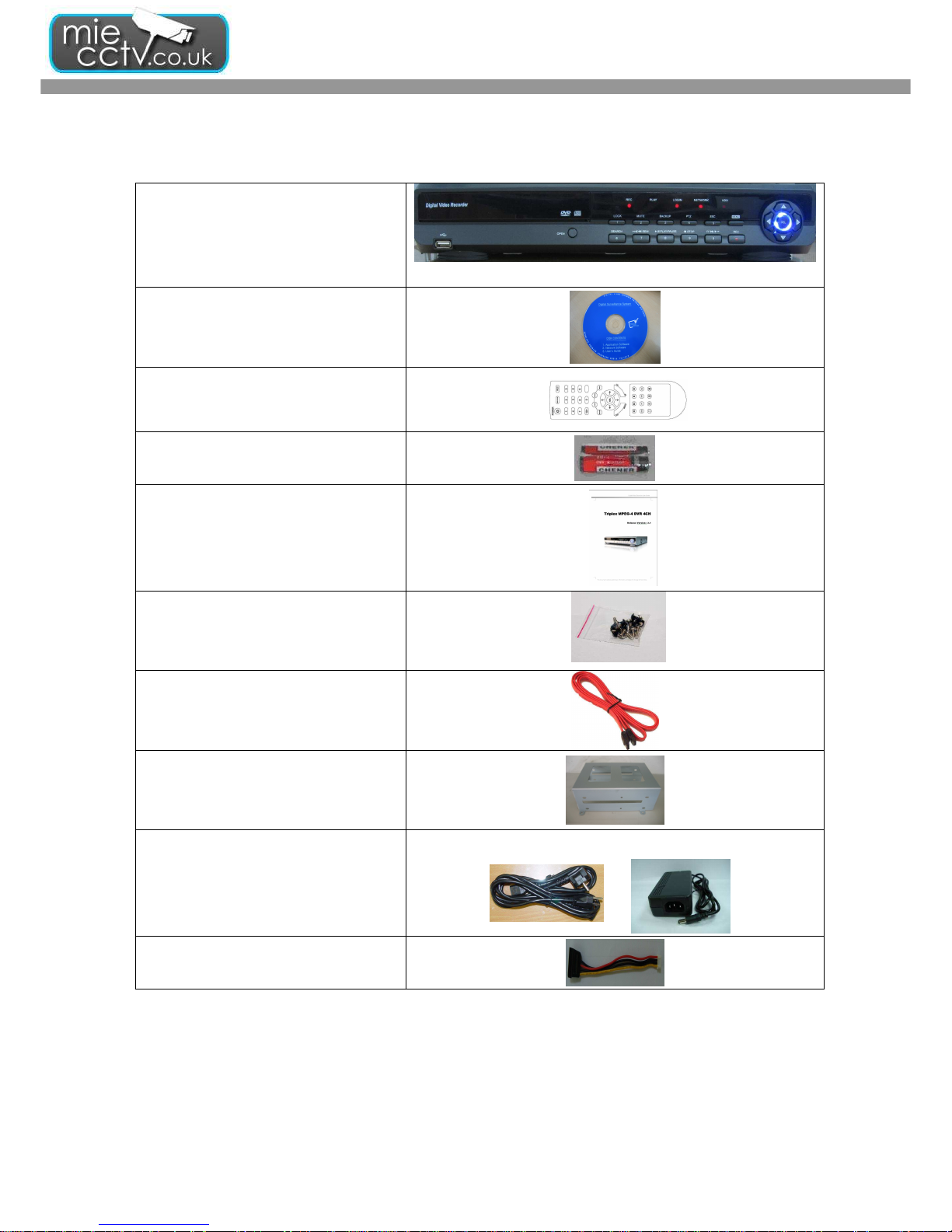
1. PACKING LIST
DVR SET
CLIENT SOFTWARE CD
REMOTE CONTROLLER
BATTERY
MANUAL
SCREWS
SATA HDD CABLE
HDD BRACKETS
POWER CABLE & Adaptor
SATA Power Cable
DVR User guide
- 6 -
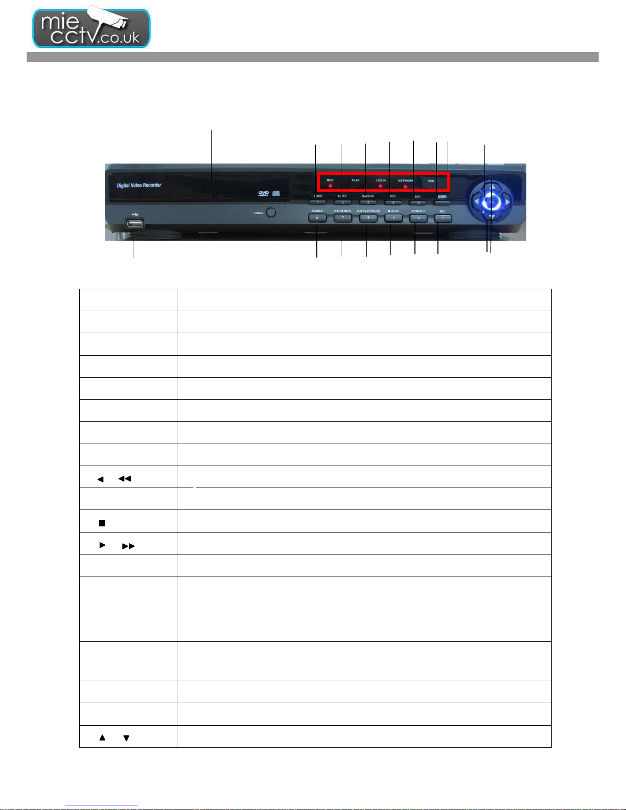
2. PANEL LOCATION
2-1 FRONT PANEL CONTROLS
○
16
○17
Control Keys Description
○
1
LOCK
In LIVE mode, It locked all accounts.
○
2
MUTE
In LIVE mode, It make to stop Audio.
○
3
BACKUP
In LIVE mode, press to display the BACKUP menu.
○
4
PTZ
In LIVE mode, press to display the PTZ menu.
○
5
ESC
In SETUP mode, press to return to previous page..
⑥MENU
In LIVE mode, press to display menu.
○
7
SEARCH
In LIVE mode, press to Display the search menu.
○
8
/ REW
In SETUP mode, press to reduce value. In PLAYBACK mode, press to play rewind.
○
9
PLAY / PAUSE
In SEARCH mode, press to play or pause playback.
○
10
STOP
In PLAYBACK mode, press to stop playing back.
○
11
/ FF
In SETUP mode, press to increase value. In PLAYBACK mode press to play forwards.
○
12
REC
Start or stop recording..
○
13
LED DISPLAY
REC: Recording. PLAY: Playing back
LOGIN: The status of Log in HDD: Hard disk is in use.
NETWORK: the status of Network connection
○
14
SEL MODE
In SETUP mode, press to enter values. In PLAYBACK mode, switch between full, quad, 9channel, 16-channel display in order.
⑮USB PORT
USB Port (For Backup Device)
○
16
DVD-RW DEVICE
Optional DVD-RW backup device. (CD-RW is also supported.)
○
17
/
In SETUP mode, press to move cursor up and down..
○
4
○
6
○
7
○
8
○
10
○
9
○
11
○
1
○
2
○
3
○
5
○
13
○○○○
15
○
14
○
12
DVR User guide
- 7 -
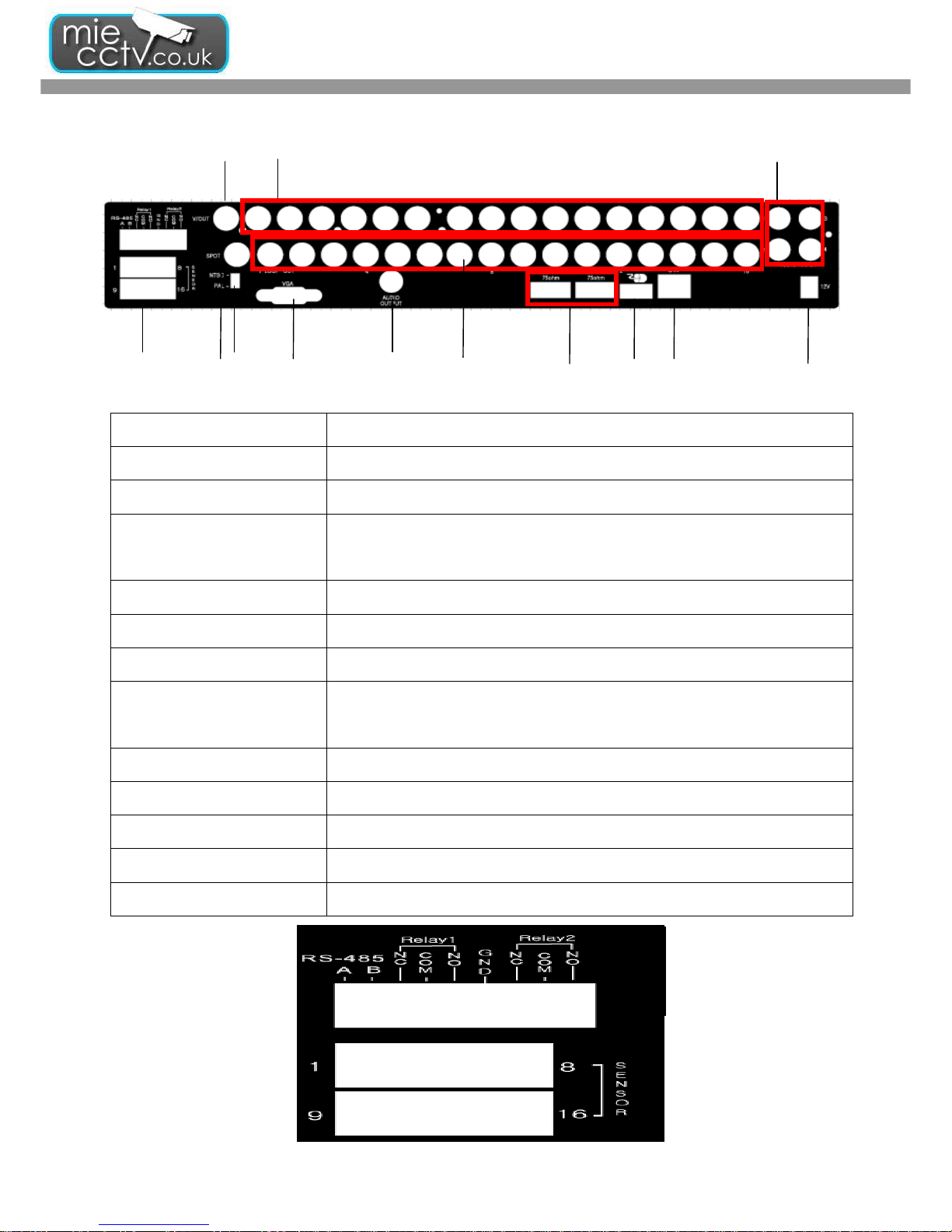
2-2 16CH REAR PANEL CONNECTORS
○
1
MAIN monitor
BNC port for the main monitor.
○
2
SPOT monitor BNC port to display full screen image of all installed cameras in sequence.
○
3
VIDEO IN BNC input ports for cameras, 16 in total.
○
4
AUDIO IN
RCA input port for audio signal. There are 4 ports available.
(corresponding to channel 1 to 4)
○
5
VGA VGA port.
○
6
LOOF OUT LOOF OUT
○
7
AUDIO OUT RCA output for audio signal.
○
8
EXTERNAL I/O
EXTERNAL I/O port for
DB 26 flat cables.
(see below for pin definition)
○
9
NTSC/PAL Switch
Switch between NTSC and PAL format.
○
10
75Ω Switch (1~16CH) If you use Loof Out function, Set Switches of each channel,
○
11
USB Port USB Port (For Mouse)
○
12
LAN Network port.
⑬ DC 12V
Socket for a DC 12V input
.
○
2
○
4
○
5
○6
○
7
○8
○
9
○
10
○
11
○
12
○
1
③
⑬

DVR User guide
- 8 -
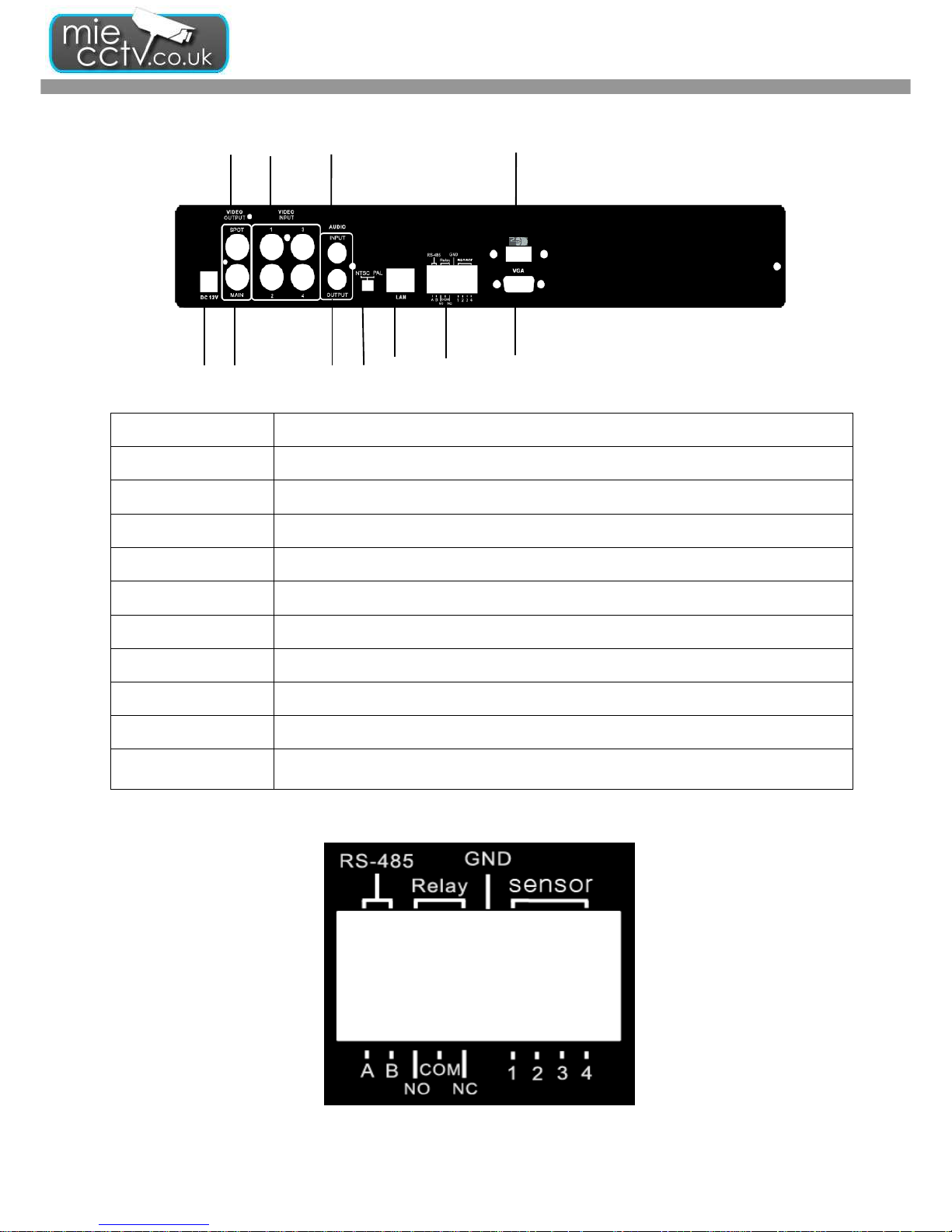
2-3 8CH REAR PANEL CONNECTORS
○
1
MAIN monitor
BNC port for the main monitor.
○
2
SPOT monitor BNC port to display full screen image of all installed cameras in sequence.
○
3
VIDEO IN BNC input ports for cameras, 8 in total.
○
4
AUDIO IN
RCA input port for audio signal. There are 4 ports available. (corresponding to channel
1 to 4)
○
5
AUDIO OUT
RCA output port for audio signal.
○
6
VGA VGA port
○
7
EXTERNAL I/O EXTERNAL I/O port (see below for pin definition)
○
8
LAN Network port
○
9
DC 12V
Socket for a DC 12V input.
⑩ USB Port USB Port (For Mouse)
③
○
1
○
9
○
2
○
6
○
7
○
8
○
4
○
5
○
10
DVR User guide
- 9 -
2-4 4CH REAR PANEL CONNECTORS
○
1
MAIN monitor
BNC port for the main monitor.
○
2
SPOT monitor BNC port to display full screen image of all installed cameras in sequence.
○
3
VIDEO IN BNC input ports for cameras, 4 in total.
○
4
AUDIO IN
RCA input port for audio signal. There is only a port of Channel 1 available.
○
5
AUDIO OUT
RCA output port for audio signal.
○
6
VGA VGA port
○
7
EXTERNAL I/O EXTERNAL I/O port (see below for pin definition)
○
8
LAN Network port
○
9
NTSC/PAL Switch
Switch between NTSC and PAL format.
⑩
DC 12V
Socket for a DC 12V input.
○
11
USB Port USB Port (For Mouse)
○
4
○
9
③
○
6
○
7
○
8
⑩
○
11
○
1
○
2
○
5

DVR User guide
- 10 -
3. PRODUCTION SPECIFICATION
Mode NO. 4CH 8CH 16CH
operation System Linux
Video
Video System
NTSC/PAL Switch
selectable
Auto Detect
NTSC/PAL Switch
selectable
Input
BNC*4,1.0Vpp,75ohm
BNC*8,1.0Vpp,75ohm
BNC*16,1.0Vpp,75ohm
CVBS 1CH BNC
Spot 1CH BNC
Loop Out without loop
BNC*16 with
termination s/w
VGA Output D-sub Standard
Audio
Input 1Ch.RCA 4Ch.RCA 4Ch.RCA
Output 1Ch.RCA 2Ch.RCA 2Ch.RCA
Control
Mouse USB Mouse 1*USD 1.1(back)
IR Controller YES
Storage Build in interface SATA*2(2*HDD or 1*HDD+1*DVD/RW)
SATA*4(4*HDD or
2*HDD+1*DVD/RW)
Display
Division 1,4 1,4,8 1,4,9,16
Zoom 2*~8*(play back zoom)2*
Recording
Compression H.264 Main Profile
Recording mood Manual, Schedule, Alarm, Holiday
Resolution
NTSC 720*480,720*240,352*240
PAL 720*576,720*288,352*288
Frame NTSC
Rate PAL
120FPS 120FPS 240FPS
100FPS 100FPS 200FPS
Quality Highest, High, Normal, Basic, Below basic
Motion Detection Sensitivity 10 Level,22*15 Grid
Water Mark YES
Playback Frame Rate 120FPS 240FPS
Speed Normal, REW&FF (1/4.1/2,2*,4*,8*,16*,32*,64*)

DVR User guide
- 11 -
Search Method Event, Time(Calendar)
Commu
-nication
Remote Software CMS,IE Brower, Mobile
Remote
Operation
Virtual DVR-Same as local OSD
Speed 60FPS 120FPS
Network Service
TCP/IP,HTTP,DDNS,SMTP(SSL)
ADSL,LAN,DHCP
3G Device WinCE5.0,6.0,Symbian,Iphone,PDA,Blackberry phone
Gui Interface Supported GUI 32Bit True Color
PTZ Protocol Pelco P/Pelco D/KND/Lilin/Samsung
Backup
Internal CD-RW,DVD-RW
External 1*USB 2.0(front)
Network YES
File H.264 Compression
General
Alarm In/Out 4/1 8/1 16/1
RS-485 1 1 1
Dimension(mm) 380(W)*350(D)*73(H)
Recovery Watchdog
Operation
Temperature
-5℃~40℃
Power
Consumption
DC12V,5A,60W DC12V,7A,84W
4. LIVE, PLAYBACK AND PTZ OPERATIONS
The IR remote controller and USB mouse operate differently under each mode; this chapter describes the functions
of them under three different modes: LIVE, PLAYBACK and PTZ.
4-1 LIVE Mode
You can monitor all channels, listen to audio signal and have some related operations under LIVE mode. This
paragraph describes the IR remote controller, USB mouse operation and on screen graphical icons under LIVE
mode.
DVR User guide
- 12 -
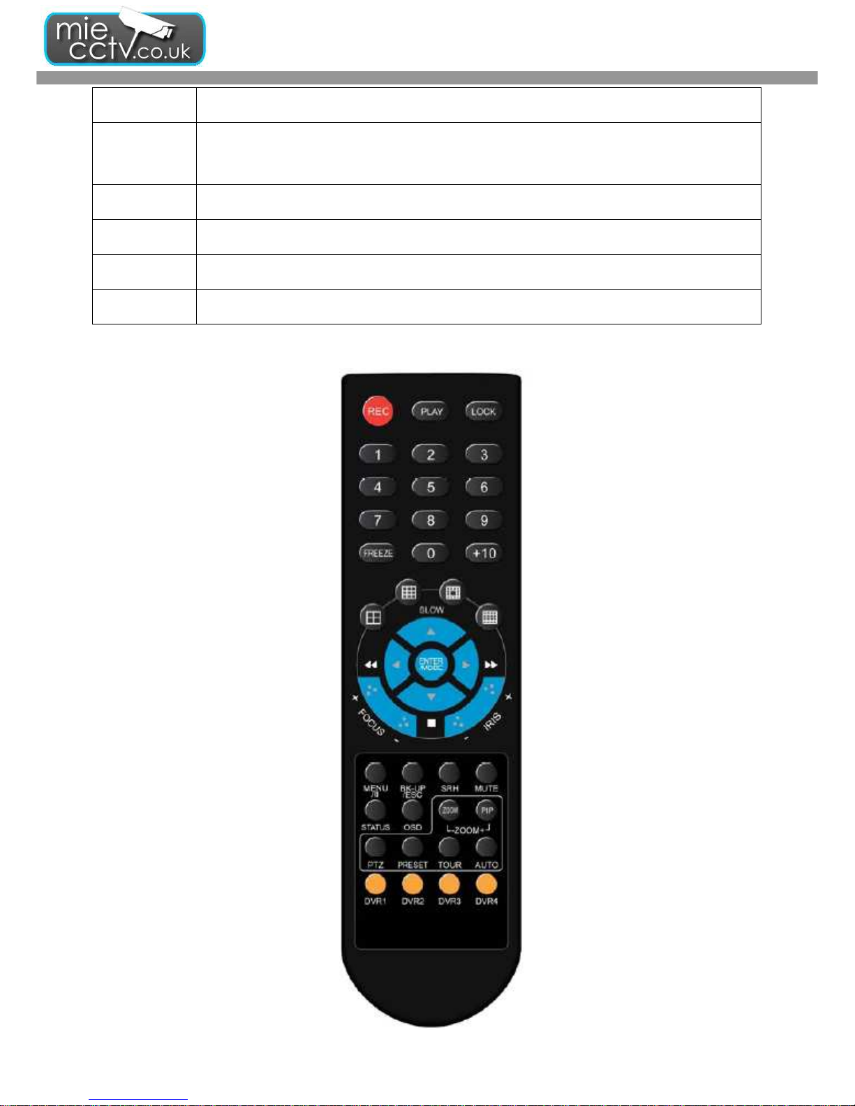
Table 4-1.1 Functions of remote control under LIVE mode
Button Description
REC
Start/Stop recording.
PLAY
Start playing back the most recently recorded segment.
LOCK
Enable/Disable the Keypad function
1,2,3,4
Select the channel to monitor in full screen
FREEZE
Turn on/off screen freeze function. ( =Pause Function)
Switch to quad display.
Switch to 9-channel display. 4ch DVR doesn’t feature this function.
Switch to 13-channel display. 4ch & 16ch DVR doesn’t feature this function.
Switch to 16-channel display. 4ch DVR doesn’t feature this function.
ENTER/MODE
Switch to full screen, quad display Sequentially.
MENU/
Enable/ Disable setup Menu.
BK-UP/ESC
Enable/ Disable backup menu.
SRH
Enable/ Disable search menu.
MUTE
Switch channel 1 output audio / turn off LIVE audio
STATUS
Enable/ Disable Status.
OSD
Turn on/off the screen display
DVR User guide
- 13 -
Button Description
Zoom/Zoom -
Enable/ Disable double screen size display. You can click on the channel name for choosing a
specific channel.
PIP/Zoom +
Turn on picture-in-picture format. Click on the channel name can switch to other channels.
PTZ
Enable PTZ control.
AUTO
In AUTO mode, all available channels will be cycled through in full screen as Auto Sequence.
ID 1~4
Switch DVR ID from 1 to 4
DVR User guide
- 14 -
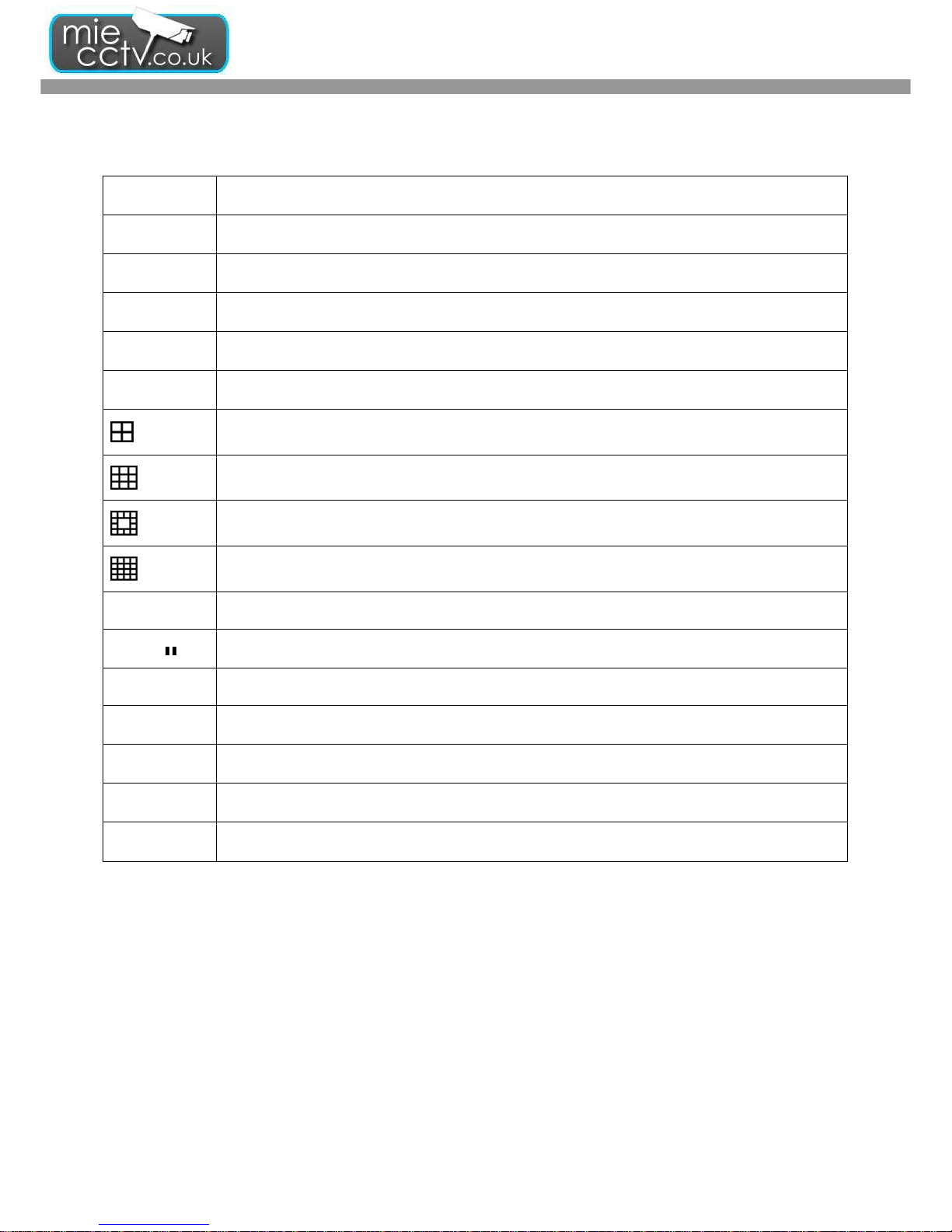
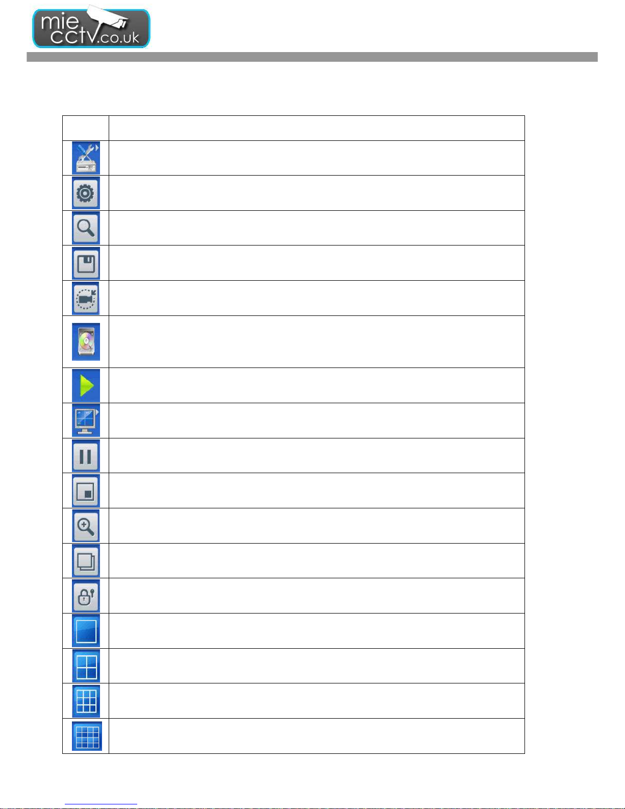
Table 4-1.2 Graphical icons that will display after right-clicking your mouse under LIVE mode.
Icon Description
Resting the cursor on this icon will bring up the following four menu icons.
Main menu.
Search menu.
Backup menu.
PTZ mode.
Turn on/off recording.
Playback.
Resting the cursor on this icon will bring up the following five display icons.
FREEZE.
PIP, picture in picture
ZOOM, double the screen size
AUTO-sequence
LOCK, activate the key lock.
Full screen display.
Quad display.
9-channel display.
16-channel display.
DVR User guide
- 15 -
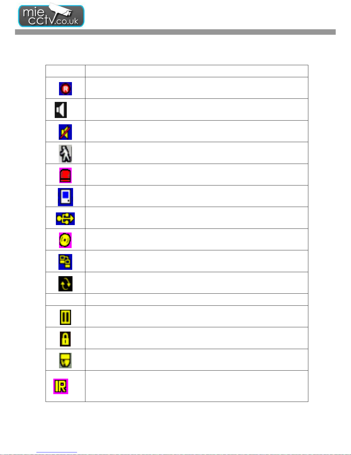
Table 4-1.3 Description of on screen graphical icons in LIVE mode
Icon Description
Recording is on
1~4
Live Audio is on
Live Audio is off
Motion detected on the channel
Sensor triggered on the channel
Video loss detected on the channel
USB device detected
DVD burner is detected
Connected to the LAN cable.
AUTO-seq is on
2X
2X zoom in is on
Freeze is on, screen is frozen ( = Pause)
LOCK is on
PTZ control is on
1~4
IR remote signal has been set to 1-4 to correspond to your 1-to-4
remote control. Meanwhile,
the standard remote control can’t control DVR under this situation. It can only be controlled
by 1-to-4 remote controls.
DVR User guide
- 16 -
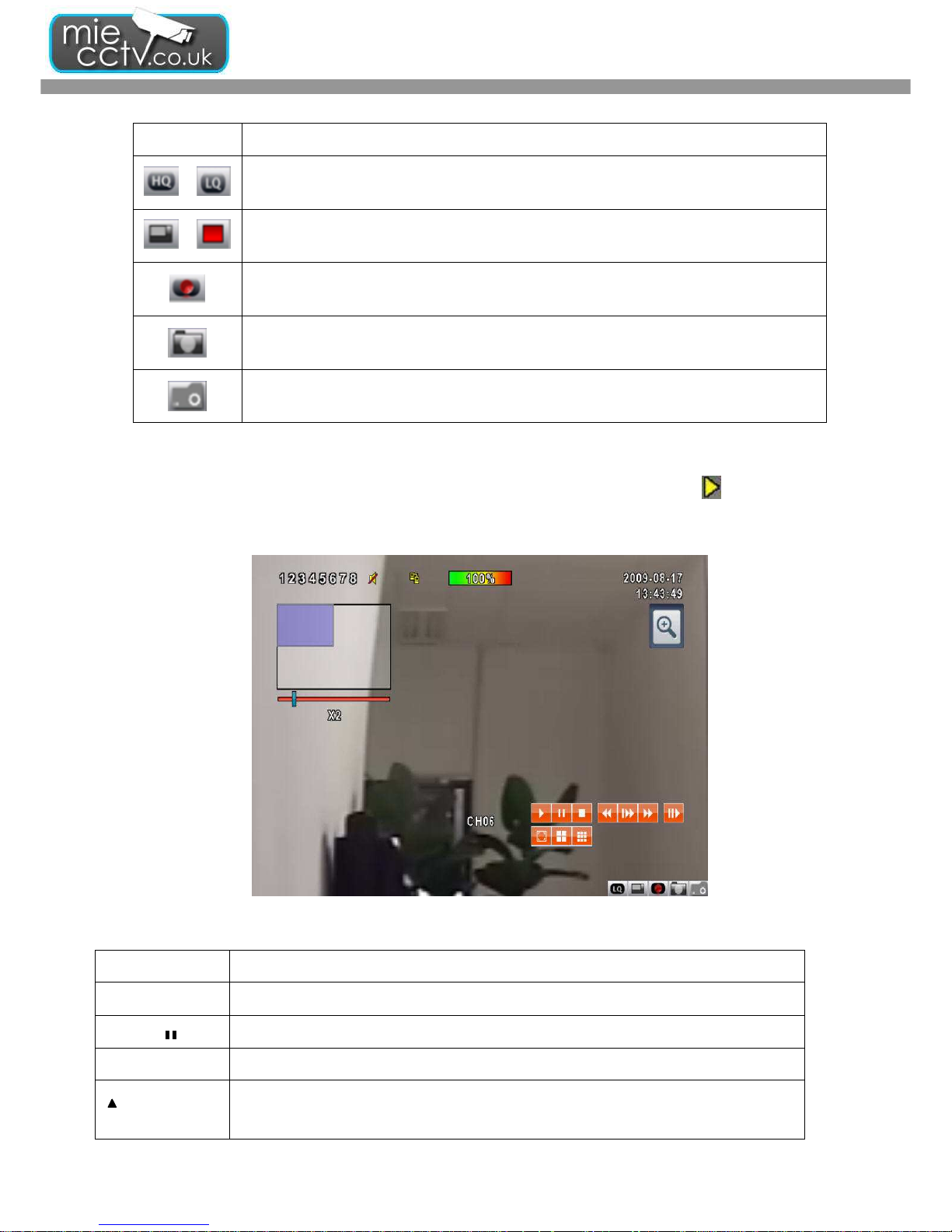
Icon Description
/
Image quality (High/Low)
/
Full screen
Record
Snap shot
Record and snap shot file saving path setup
4-2 PLAYBACK Mode
Switch to PLAYBACK mode by pressing “PLAY” under the LIVE mode, the graphical icon will show up on the
upper center of the screen and the operation panel (look at the below picture) will show up at right lower corner of
the screen. You can drag the panel by mouse to place it on any location of your screen.
Table 4-2.1 Remote control functions under the PLAYBACK mode
Button Description
ENTER / MODE
Switch to full screen, quad, 9-channel or 16-channel display.
MENU /
Turn on/off PAUSE.
PLAY
Play back at normal speed.
/ SLOW
Play back at slower speed. The speed will be slowed to 1/2, 1/4, 1/8, 1/16 by each
pressing of the button till the slowest limitation of 1/16 of the normal speed. Current
DVR User guide
- 17 -
playback speed is shown in the upper center of the screen.
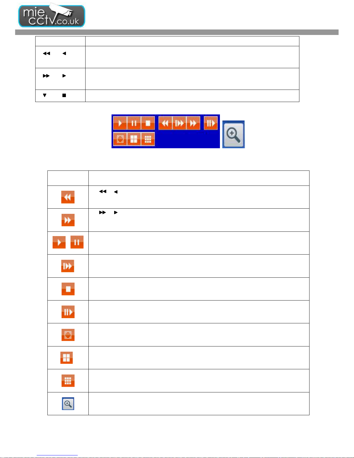
/
Fast rewind. Each press increases the speed to the next level. There are six speeds:
2X, 4X, 8X, 16X, 32X and 64X.
/
Fast forward. Each press increases the speed to the next level. There are six speeds:
2X, 4X, 8X, 16X, 32X and 64X.
/
Stop playback.
Table 4-2.2 The mouse operation under the PLAYBACK mode.
Icon Description
「 / 」 Fast rewind
「 / 」Fast forward
/
Play/pause
「▲
▲▲
▲ / SLOW」,slow playback
「▼
▼▼
▼ / ■」stop playback
Playback channel by channel with snap shot display
Full screen display
Quad display
9-channel display
Zoom-in display
DVR User guide
- 18 -
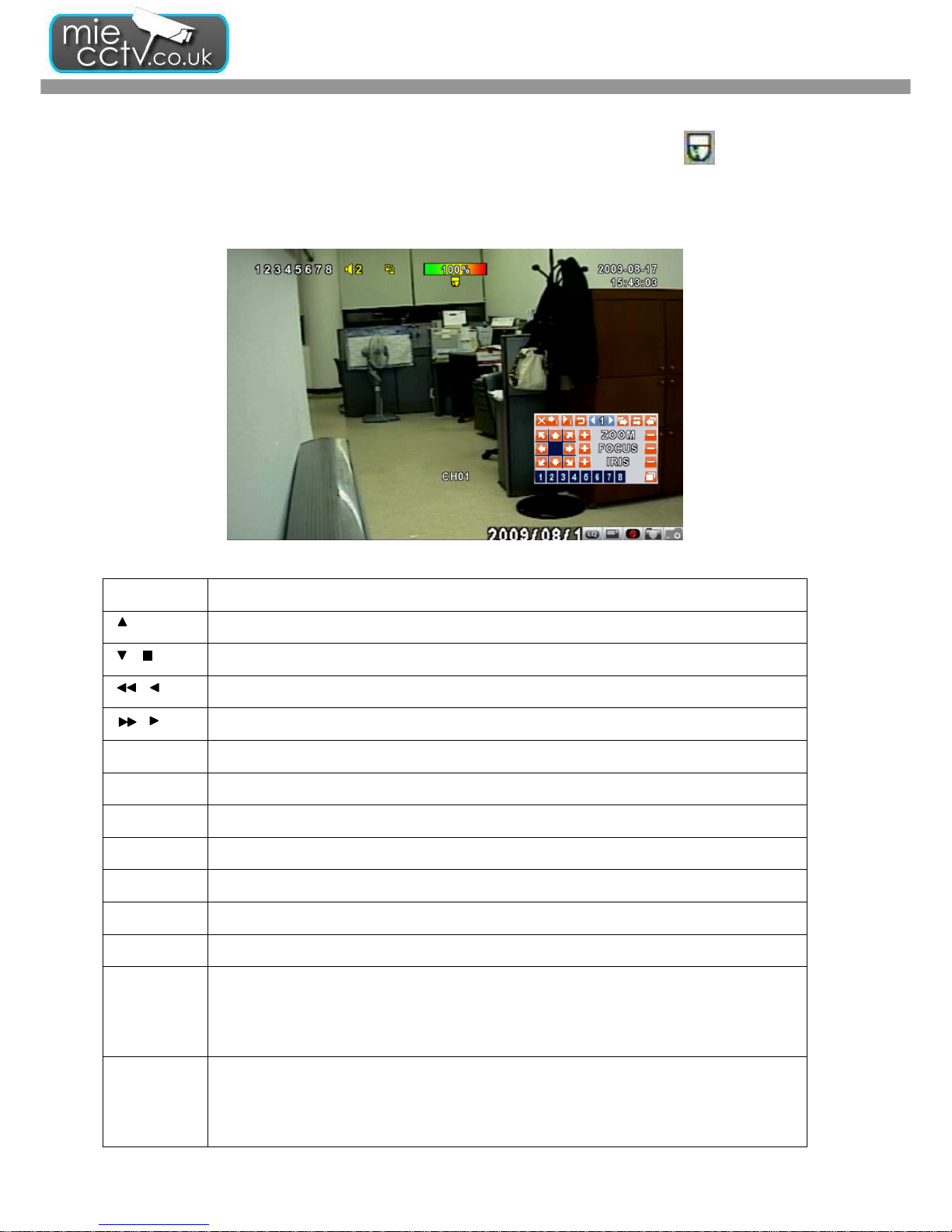
4-3 PTZ Mode
Switch to the PTZ mode by pressing “PTZ” button under the LIVE mode. The PTZ icon will appear on upper
center side of screen and the control panel will appear on the down right side of screen.
Table 4-3.1 Remote Control functions under the PTZ mode
Button
Description
/ SLOW
Move PTZ up.
/
Move PTZ down.
/
Move PTZ to the left.
/
Move PTZ to the right.
ZOOM +
PTZ zoom-in.
ZOOM -
PTZ zoom-out.
FOCUS +
PTZ focus-in.
FOCUS -
PTZ focus-out.
IRIS +
PTZ iris-open.
IRIS -
PTZ iris-close.
TOUR
Activate PTZ pre-set tour. *
PRESET+
Number
Setup the Preset location
Press “PRESET” key first then two-digit number; DVR will set the current PTZ location at
entered preset number.
PLAY+
Number
Go to Preset location
Press “PLAY” key first then two-digit number, PTZ will go to the correspondent preset
number location.
 Loading...