

MID WEST PRODUCTS MH-4451 Owner's Manual

45” TRAILING PAVEMENT/LEAF/LAWN SWEEPER
MODEL MH-4451
Owner’s Manual and Parts List
SAVE THIS MANUAL
You will need this manual for the safety instructions, assembly instructions and parts list. Put it in a
safe, dry place for future reference.
©2017 Mid West Products, Inc. -1- Form No. M1-1604

Your new Trailing Lawn Sweeper is precision
manufactured using the finest in tools and
materials. Although it is ruggedly constructed,
do not subject it to misuse. CAUTION: DO NOT
PULL YOUR UNIT TOO CLOSE TO A FIRE –
the Brushes and Hamper will burn. Be sure to
wipe off your unit after each use. Store unit in a
dry place out of direct sunlight. Do not permit
the Lawn Sweeper to stand in the hot sun unless
it is in actual use.
You will find many work saving uses for your
Lawn Sweeper. Use it in early Spring to give
your lawn a good healthful scrubbing. Use it
throughout the Spring and Summer both before
and after mowing.
Sweeping before mowing stands up grass for a
clean, even cut - and protect your Mower from
sticks, stones, or nuts, which might damage the
blades of your Mower. After mowing, your
Lawn Sweeper will whisk away unsightly grass
clippings – leaving your lawn velvety smooth.
This Lawn Sweeper was in perfect condition
when it was shipped to you. If any damage is
found when it is unpacked, save the carton and
immediately request the delivery carrier to make
an inspection report.
HITCH ASSEMBLY
MANUAL
HEIGHT ADJUSTMENT HANDLE
WIND APRON
Your Lawn Sweeper comes mostly assembled on the pallet. The Hitch Assembly and Height
Adjustment Handle may need attached:
PARTS LIST OF MH-4451
©2017 Mid West Products, Inc. -2- Form No. M1-1604
Assembly
Remove all Sweeper Parts from Carton. All “Right” and “Left” directions are in reference to position
behind the Lawn Sweeper.
Tools required for assembly: Two (2) 7/16” – 1/2" Combination Wrench, one (1) Adjustable Wrench,
and one (1) Pliers. Lay out all Parts, have Tools handy, and follow these few Instructions:
Step 1: Install Adjustment Tube (7) to Chassis. Insert Adjustment Tube through rectangular hole of
Adjustment Bracket. Fasten the Adjustment Tube with Bolt (55) and Nut (11). (Note – Bolt (55) and
Nut (11) are already slightly tightened on the Chassis.) Pull Spring (33) and Retainer Tube (34) forward
until the Spring is secure in the notched location of the Adjustment Bracket.
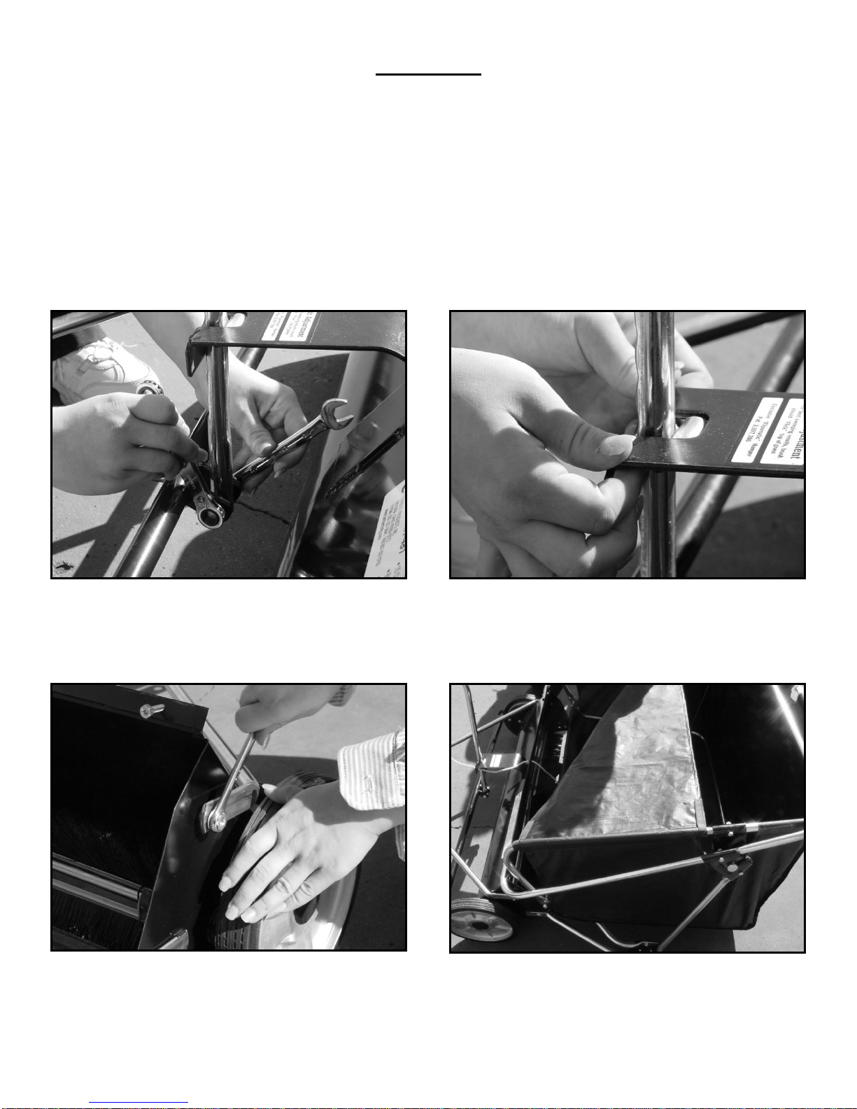
Step 2: Install Hitch Tube Assembly by removing Pilot Nuts (60), which are already slightly tightened
on the Chassis. Install Hitch Tube Assembly on Bolts (61) and Secure with Pilot Nuts (60). (See Image:
Below – Left)
Step 3: Take Wind Apron (65) and fasten Velcro to both Side Hamper Tubes (42). Fasten the other
Velcro strap to the rear of the Hamper Pivot Brackets (44). (See Image: Above – Right)
©2017 Mid West Products, Inc. -3- Form No. M1-1604
 Loading...