

MID WEST PRODUCTS LC-R08E Owner's Manual

©2019 Mid West Products, Inc. -1- Form No. M8-1728
LOG CART – MODEL LC-R08e
Owner’s Manual and Parts List
SAVE THIS MANUAL
You will need this manual for the safety instructions, assembly instructions and parts list. Put it in a
safe, dry place for future reference.
Additional Information/Link to PDF Copy of this Manual:
WARNING
• Read instructions and Warnings before set up and use.
• Check to insure product is not damaged prior to use. If product is damaged, do not use.
• Do not exceed cart’s weight capacity of 200 lb.
• Do not exceed each tire’s maximum permissible inflation pressure of 30 psi.
• Only use product as intended. Do not attempt to jump or stand on product.
• Not for use by unsupervised children.
©2019 Mid West Products, Inc. -2- Form No. M8-1728
• Please read and understand these
Instructions before assembling your Log Cart.
• Check that you have all components.
• 1/2” and 9/16” Wrenches required for
assembly.
Assembly Instructions:
Step 1: Attach Top Handle/Front Support (#1)
by inserting into the Side Frames (#3)
and securing using two each Bolts (#6),
Flat Washer (#11), Lock Washer (#10),
and Nut (#7). Insert Wheel Axle (#5)
between the two Side Frames (#3). Do
not completely tighten Bolts and Nuts
until told to do so.
Step 2: Attach Handle/Front Support (#1) by
inserting into opposite end of Side
Frames (#3) and securing using two
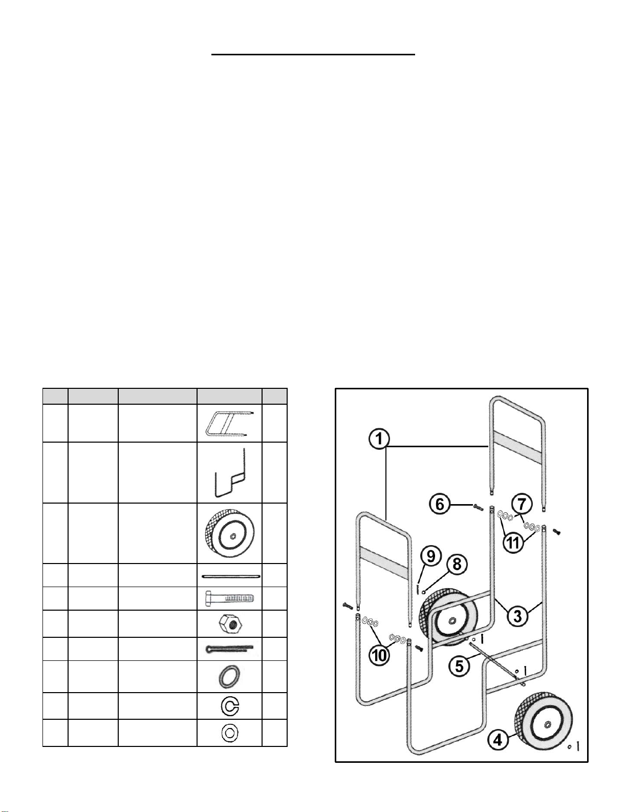
Key
Part No.
Description
Image
Qty
1
52-0001
Handle/Front
Support
2
3
52-0003
Sides
2
4
52-0004
Wheel & Tire
2
5
52-0005
Axle
1
6
52-0006
Bolt 4
7
52-0007
Nut 4
8
52-0008
Cotter Pin
4
9
52-0009
Big Washer
4
10
52-0010
Lock Washer
4
11
52-0011
Flat Washer
4
each Bolts (#6), Flat Washer (#11),
Lock Washer (#10), and Nut (#7).
Step 3: Insert Axle (#5) through one of the Sides
(#3), then slide on two Big Washers (#8)
before sliding the Axle (#5) through the
other Side (#3). Center Axle (#5), Slide
Big Washers (#8) [one to each side] out
against the Sides (#3). Secure Axle
(#5) with a Cotter Pin (#9) in the hole
just inside the Big Washers (#8).
tightness.
Step 4: Attach one Wheel (#4) on each side of
the Axle (#5) and secure with Washers
(#9) and Cotter Pin (#8).
Step 5: Now Tighten all parts that are using
Bolts (#6) and Nuts (#7) as shown in the
Diagram. Assembly is now complete!
Log Cart – Model LC-R08e
 Loading...