

MID WEST PRODUCTS GSF-31M-NT Owner's Manual
©2018 Mid West Products, Inc. -1- Form No. M15-1603
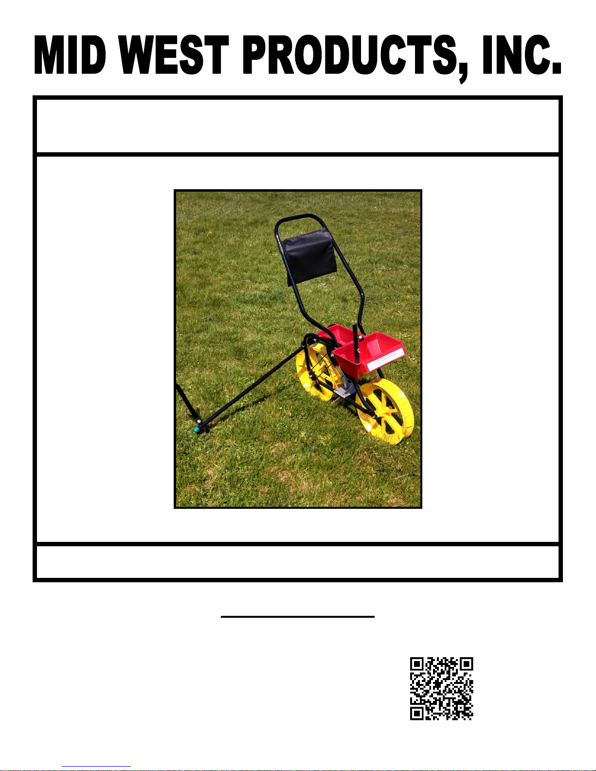
VEGETABLE GARDEN SEED ROW PLANTER
MODEL GSF-31M-NT
No Tools Required Owner’s Manual and Parts List
SAVE THIS MANUAL
You will need this manual for the safety instructions, assembly instructions and parts list. Put it in a
safe, dry place for future reference.
Additional Information/Link to PDF Copy of this Manual:
©2018 Mid West Products, Inc. -2- Form No. M15-1603
VEGETABLE GARDEN SEED ROW PLANTER AND FERTILIZER APPLICATOR
NO TOOLS ASSEMBLY
OPERATING
MAINTENANCE
PARTS LISTING
ASSEMBLY
1. Remove two Wing Nuts (37) from the Hex
Bolts (44) which are located at the top of
Lower Handle Tubes (10). Install the Upper
Handle Tube (11) onto the Hex Bolts (44) in
the Lower Handle Tubes (10) and secure
with previously removed Wing Nuts (37).
2. Remove Wing Nut (37) from Hex Bolt (45) in
the fertilizer section of the Seed/Fertilizer
Hopper (1). Install Fertilizer Lever (19) onto
Hex Bolt (45) and secure with previously
removed Wing Nut (37).
3. Unscrew Plastic Knob (48) from Row Marker
Tube (21).
4. Assemble Row Marker Tube (21) to the Row
Marker Bracket (20) using the Hex Bolt (38)
that is inserted into the end of the Row
Marker Tube (21), with the head of the Hex
Bolt pointing away from the Seed/Fertilizer
Hopper (1).
5. Screw the previously removed Plastic Knob
(48) onto the Hex Bolt (38) to assemble the
Row Marker Tube (21) to the Row Marker
Bracket (20). Do not fully tighten hardware,
allowing row Marker Tube to pivot from side
to side.
OPERATION
1. To install the desired Seed Plate, hold the
Seed Plate at an angle with the bottom
against the straight wall in the Hopper. Line
up the slots in the Seed Plate with the raised
portions of the Hub, hold it firmly against the
inside of the Hopper and rotate it
approximately ½” in the “ON” direction as
indicated by the arrow on the Plate until the
cam action locks the Seed Plate in place on
the Hub. Do Not Force! OFF and ON
directions are indicated on the Seed Plates
with arrows.
2. Next, set the planting depth with the wedgeshaped Furrowing Shoe located directly
under the Hopper. Move Furrowing Shoe
until top edge is in line with desired planting
depth. Retighten Wing Nut (35) after
adjustment is made. Check the depth by
moving the Seeder forward a few inches.
3. Pour seeds in the Seed Hopper. CAUTION:
Do not fill the Hopper above the center of the
Seed Plate.
4. Pour fertilizer into fertilizer hopper.
CAUTION: Do not over fill the Hopper.
Allow 1” from fertilizer to top edge of Hopper.
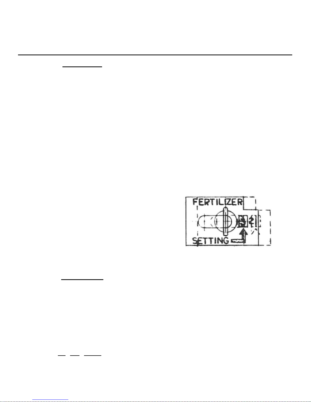
5. Adjust fertilizer flow by loosening Wing Nut
on Fertilizer Hopper. Slide calibrated plate
to desired setting and tighten Wing Nut.
Before filling, shut off Fertilizer Control.
6. Mark out the first row in your garden. Lower
the Row Marker Shaft and adjust the Row
Marker to the proper width for the next row.
You are now ready to plant
7. To empty seeds, remove Plug (2) from Seed
Hopper by simply putting pressure on center
of Plug and push inward. Pour seeds into a
clean container.
8. Empty fertilizer by placing a clean container
under Fertilizer Hose, setting Adjustment
Plate to No. 3 setting and open control,
allowing fertilizer to flow into the container.
9. To remove Seed Plate, hold Pulley and Belt
stationary with one hand and rotate the Seed
Plate approximately ½” in the “OFF”
direction indicated by an arrow on top of the

©2018 Mid West Products, Inc. -3- Form No. M15-1603
Seed Hopper. Push the Seed Plate off the
Hub through the hole just above the Pulley.
It will slip off easily.
NOTICE: Keep your Seed/Fertilizer Hopper
clean and free from sand, grit, and seed
treating materials.
SEED PLATE SELECTION GUIDE
Selection information as to seed size and
spacing are also found on your Seed Plates.
15-1018-1 Has a 9 inch seed drop spacing,
plants corn and sunflowers.
15-1018-2 Has a 3 ½ inch seed drop spacing,
plants small and medium peas
and beans, also similar seeds.
15-1018-3 Has 3 ½ inch seed drop spacing,
plants variety of peas and beans
including baby Lima.
15-1018-4 Has a 3 ½ inch seed drop spacing,
plants beets, extra small peas and
beans, okra, and related seeds.
15-1018-5 Has a 3 inch seed drop spacing,
plants radishes, small beets, and
seed of like size.
15-1018-6 Has 4 inch drop spacing, plants
most small seeds such as turnips,
mustard, lettuce, carrots, kale,
collards, endive, spinach,
rutabaga, parsnips, parsley, and
rhubarb. This plate may also be
used to plant seeds for vegetable
that are sometimes grown from
plants. These include broccoli,
brussel sprouts, cabbage,
cauliflower, celery, onions, and
peppers.
NOTE: When changing Seed Plates, be sure
Hopper is empty.
FERTILIZER ADJUSTMENT SETTINGS
Granular Fertilizer must be free flowing without
lumps.
No. 1 setting – 1 lb per 100 ft.
No. 2 setting – 2 lb per 100 ft.
No. 3 setting – 3 lb per 100 ft.
Consult your fertilizer dealer for further
application data. We recommend that Users
contact their Local Ag Agent with the USDA
(United States Department of Agriculture) for
their recommendations on the proper fertilizers
to use in their particular County.
HELPFUL OPERATING SOLUTIONS
PROBLEM:
1. The Seeder will not go more than a foot or
two . . .
2. The peas, beans, and/or corn fly out of the
hopper . . .
3. The seeds break . . .
SOLUTIONS:
Be extra careful, do not back up the Seeder.
(Lift the Seeder to reposition the GSF 31M)
So, what happens if the Seeder is pulled
backwards?
1. The Seed Plate will come loose, whenever
the rear Wheel of the Seeder is pulled
backwards. If the Seed Plate loosens, even
a little, then seeds get caught between the
Seed Plate and the side of the Seed Hopper.
This causes the Seed Plate to quit turning.
2. As the rear Seeder Wheel is still being
pushed, the plate tightens and seeds that
are caught between the Plate and the
Hopper wall, then get crushed. Once the
seeds are crushed, then the Plate can’t turn
and the seeds are all planted on one spot or
they clog the Seed Chute.
The Upper Pulley and Spindle are too tight:
1. Remove the Belt (Item 16) — it is easiest to
remove the Belt located on the Lower Pulley
(Item 15) — pulling the Belt slightly to one
side and at the same time.
2. Check the Upper Pulley (Item 15) that is
connected to the Spindle (Item 13).
3. If the Pulley/Spindle Assembly does not spin
freely or is tight, then back off the Screw
(Item 40) one-fourth to one-half turn.
 Loading...