

MIDWEST FASTENERS CD50 Owner's Manual

CD 50
Solid State
Capacitor Discharge
Stud Welding System
Owner’s Manual
• Installation
• Operation
• Maintenance
©2001
450 Richard Street
Miamisburg, OH 45342
Phone: (800) 852-8352
Fax: (937) 866-4174
MIDWEST FASTENERS, INC.
, all rights reserved.

TABLE OF CONTENTS
GENERAL
INTRODUCTION
INSTALLATION
SETUP& OPERATION
War ranty ......................................................................................... 4
Safety Precautions .......................................................................... 5
What is Stud Welding ? ................................................................... 6
How Does CD Stud Welding Differ From ARC Stud Welding? .... 6
CD 50 Overview ............................................................................ 8
CD 50 Installation .......................................................................... 9
CD 50 Setup ................................................................................. 10
Gun Set Ups
Insulation Pins ........................................................................ 11
Insulation Pins with Collet Protector ..................................... 11
Insulation Pins with Internal Stop .......................................... 12
Weld Studs ............................................................................. 12
Controller Adjustment .................................................................. 13
Making A Test Weld...................................................................... 13
MAINTENANCE
TROUBLESHOOTING
SPECIFICATIONS
Weld Quality ................................................................................. 14
Preventive Maintenance ................................................................ 15
Troubleshooting ............................................................................ 15
CD 50 Welder Specifications ....................................................... 18
CD 50 Welder Exploded View & Parts List ................................. 19
CD 2 Gun Specifications .............................................................. 20
CD 2 Gun Exploded View & Parts List ........................................ 21
CD 50 Electrical Schematic.......................................................... 22
Notes ............................................................................................. 23

WARRANTY
All parts used in the assembly of your MIDWEST FASTENERS Stud
Welding System are fully guaranteed for Ninety (90) days from delivery
date. In addition, the Welding Capacitors are fully guaranteed for a period
of One Hundred and Twenty (120) days from delivery date.
Under this warranty, MIDWEST FASTENERS reserves the right to repair
or replace, at its option, defects in material or workmanship which occur
during the warranty period. Notice of any claim for warranty repair must
be furnished to MIDWEST FASTENERS within ten (10) days after the
defect is discovered. MIDWEST FASTENERS does not assume liability
for shipping, or liability for any labor or material related to use of this
system unless such costs are expressly authorized in writing by MIDWEST
FASTENERS.
MIDWEST FASTENERS, INC. does not warrant defects in welders, parts
or accessories resulting, from abuse, improper installation, or for reasons
beyond its control.
This warranty is valid only when welding pins and/or studs approved by or
purchased from MIDWEST FASTENERS.
MODEL NO.
SERIAL NO.
SHIPPING DATE
VOLTAGE REQUIRED
4 ©2001
MIDWEST FASTENERS, INC.
—
CD 50 Stud Welder
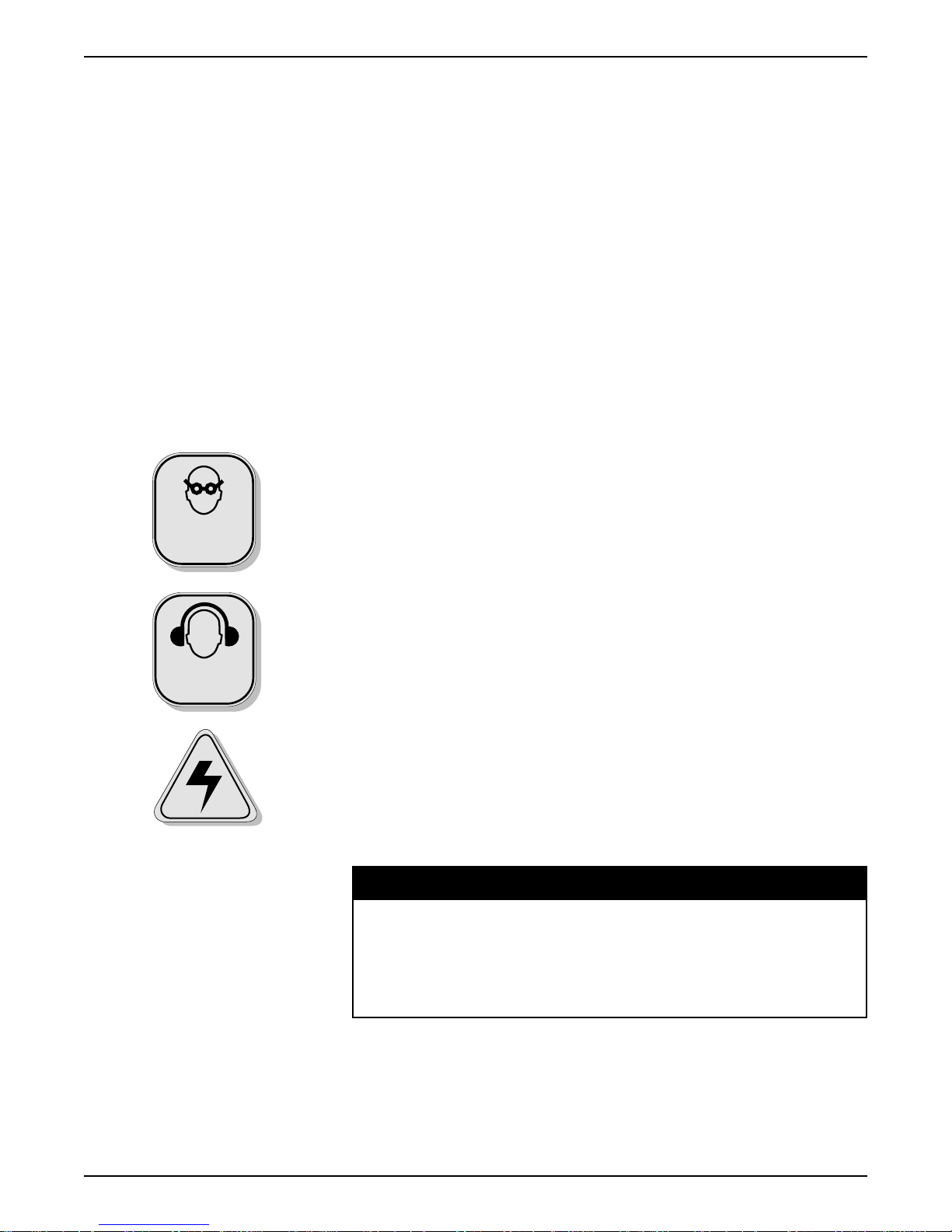
SAFETY
PRECAUTIONS
EYE
PROTECTION
•Comply with all electrical, fire and other applicable codes or ordinances
in the installation and use of stud welding systems.
•Remove all combustible or volatile materials from the weld area.
Although weld splatter resulting from stud welding is normally minimal,
proper precautions should be taken when welding near or through
combustible materials to insure that sparks or weld material do not come
in contact with combustible material.
•Recommend wearing of eye protection at all times when welding.
Spectacle type frames with Shade No. 3 absorptive and filter lens and
side shields are suggested. Never look directly at the weld arc without
wearing eye shields.
•Recommend use of proper ear protection with all CAPACITOR
DISCHARGE stud welding systems. The stud welding operator and
anyone working within five (5) feet of the stud welding operation should
use ear protection devices.
•Use of protective clothing is suggested. Type of clothing will vary as to
application, weld position and stud welding being used; however, in all
cases, it should be fire resistant and sufficient to protect welding
operator from weld splatter and material.
HEARING
PROTECTION
HIGH VOLTAGE
•Keep hands, clothing, etc. away from the weld stud, chuck and all other
parts in contact with them during the weld cycle.
•Keep weld cable and connectors in good condition. Inspect periodically
for broken insulation and/or other electrical hazards.
•Do not operate with worn or poorly connected cables. Inspect all cables
often for bare or exposed wires, broken insulation layers and/or loose
connections. Repair all such connections before welding use.
•Do not stand in water or on damp surfaces while welding. Avoid wearing
wet or sweaty clothes. Do not weld in the rain.
WARNING
Use extreme caution when servicing or troubleshooting
any component of this stud welding system.
If possible, turn all power controls “OFF”
and disconnect all electrical cables.
For other suggested precautions, safe practices, etc.
regarding welding, refer to
“Safety in Welding and Cutting”,
ANSI Z49.1, American National Standards Institute.
©2001
MIDWEST FASTENERS, INC.
—
CD 50 Stud Welder 5
WHAT IS STUD
WELDING?
Stud welding is a welding process where a “stud” (or similar metal part) is
instantaneously end-joined to a metal workpiece. This process involves the
same basic principles and metallurgical aspects as any other welding
process.
The equipment required to stud weld is composed of a direct current power
supply, a controller, a weld gun and cables to tie the system components
together. In most systems the power supply and controller are combined into
one unit called the “Welder.”
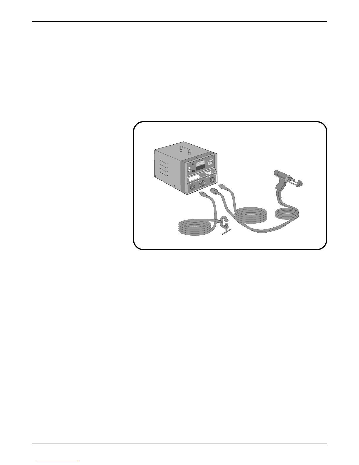
CD 50 STUD WELDING SYSTEM
(P/N: CDSW-050-01)
Controller
CDSW-050-00
N
R
E
O
W
O
P
E
G
A
T
L
O
V
D
L
E
W
F
F
O
G
L
O
R
T
CD 50
N
O
C
D
C
+ –
E
L
B
A
C
D
N
U
O
R
G
X
A
M
E
N
G
I
A
M
T
L
O
V
N
U
Weld Gun
CDSG-201-06
Ground Cable
CDGC-200-15
The stud welding process is as follows. The stud is placed
in the collet of the
“Weld Gun” and then positioned against the workpiece. The weld gun trigger
is depressed and t
hrough operation of the stud welding controller and the
design of the stud, an arc is drawn which melts the base of the stud and a
proportionate area of the workpiece. The stud is then forced by the weld gun
into the molten pool and held in place until the metals resolidify. This high
quality fusion weld is completed in milliseconds.
HOW DOES
CD STUD WELDING
DIFFER FROM
ARC STUD WELDING?
6 ©2001
There are two different stud welding processes:
• Capacitor Discharge (called “CD ” for brevity) and
• Arc.
The difference between these two methods involves the power source used
to provide the welding current, the workpiece size, base material and the
stud design.
MIDWEST FASTENERS, INC.
—
CD50 Stud Welder
CD STUD WELDING
The CD stud welding process produces weld power through a rapid
discharge of the stored energy from a bank of capacitors. This stored
energy is usually derived from a standard 115 volt AC source. CD stud
welding, as a general rule, is used for studs 5/16" and less in diameter,
(or where thin base metals or dissimilar metals are to be joined.)
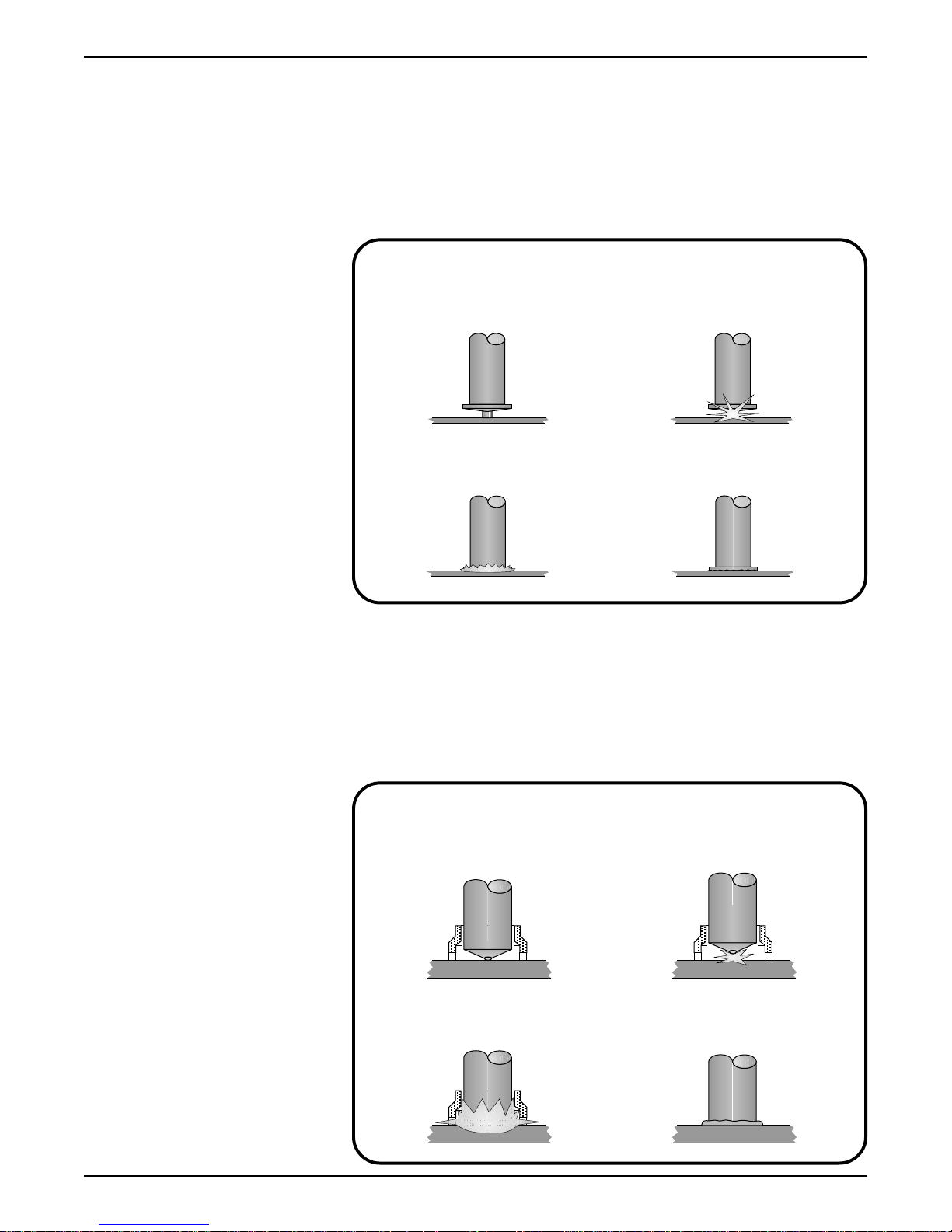
“CD” STUD WELDING PROCESS
ARC STUD WELDING
1. Stud is placed against workpiece
and weld gun trigger depressed
3. Weld gun forces stud
into molten metal
2. Stored energy is discharged
through special tip
4. Weld solidifies in
miliseconds
The ARC stud welding process produces weld power through one of three
standard DC welding power sources. These are Transformer-Rectifier type,
Motor/Generator type, or Storage Battery type. A ceramic ferrule is
required in ARC stud welding to maintain the proper atmosphere in the
weld area. ARC stud welding is generally used for studs over 1/4" in
diameter or where heavier base metals are involved.
©2001
MIDWEST FASTENERS, INC.
“ARC” STUD WELDING PROCESS
1. Stud is placed against workpiece
and weld gun trigger depressed
3. Weld gun forces stud
into molten metal
—
CD 50 Stud Welder 7
2. Stud is lifted by weld gun
and initiating arc is drawn
4. Weld solidifies and
ferrule is removed

OVERVIEW – CD50
CAPACITOR DISCHARGE
STUD WELDER
The CD 50 is a capacitor discharge stud welder. The weld energy is stored
in capacitors located inside the control unit. The amount of stored energy
can be controlled by rotating the voltage control knob located on the front
panel.
CD weld studs, or pins, used with the CD50 must have a specially
designed projection at the weld end. When the stud
gun and placed against the workpiece
the following occurs:
1. The energy stored in the capacitors travels through the weld cables to
the stud.
2. The rapid rise in current ignites the projection and allows a welding
arc to be established between the stud and the workpiece.
3. The arc melts the base of the stud and a portion of the workpiece.
4. The spring pressure inside the welding gun forces the stud into the
molten metal pool created by the arc.
5. The cycle ends upon contact of the stud to the workpiece.
, and the trigger switch is depressed,
is inserted into the weld
HEARING
PROTECTION
HIGH VOLTAGE
6. The welding gun is then removed. Upon removal, the controller will
automatically recharge to the set voltage.
CAUTION
The noise generated by stud welding
may exceed allowable levels
established by O.S.H.A. For this reason
it is recommended that proper ear protection be worn
by the operator and anyone working in the immediate area.
WARNING
Voltages inside the unit can reach 200 volts D.C.
even if the unit is turned off. All repair work
should be handled by factory trained personnel.
8 ©2001
MIDWEST FASTENERS, INC.
—
CD 50 Stud Welder
 Loading...