

Midwest CF24-120N, CF26-120N, CF30-120N Service Manual
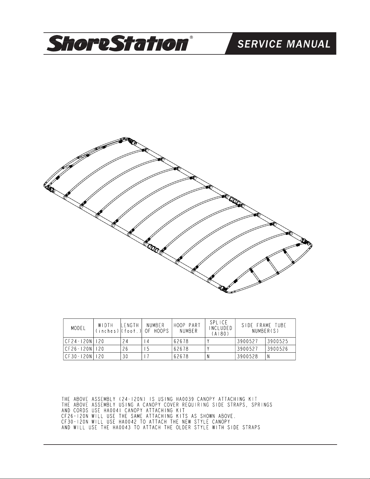
CF24-120N, CF26-120N & CF30-120N Canopy Frames Fitting:
Aluminum Hoist Models: SSV30/40120, SSPV30/40120, SS30/40120 DW,
SSPV30/40120 DW, SSV50120 & SSV50120 DW
Hydraulic Hoist Models: SSV40120 HYD, SSV60120 HYD, SSV40120 HYD DW &
SSV60120 HYD DW
Steel Hoist Model: SSV45120
Diagram A
Midwest Industries, Inc. Ida Grove, IA 51445 800.859.3028 www.shorestation.com 0003526
Page 1 REV A 4/12/06
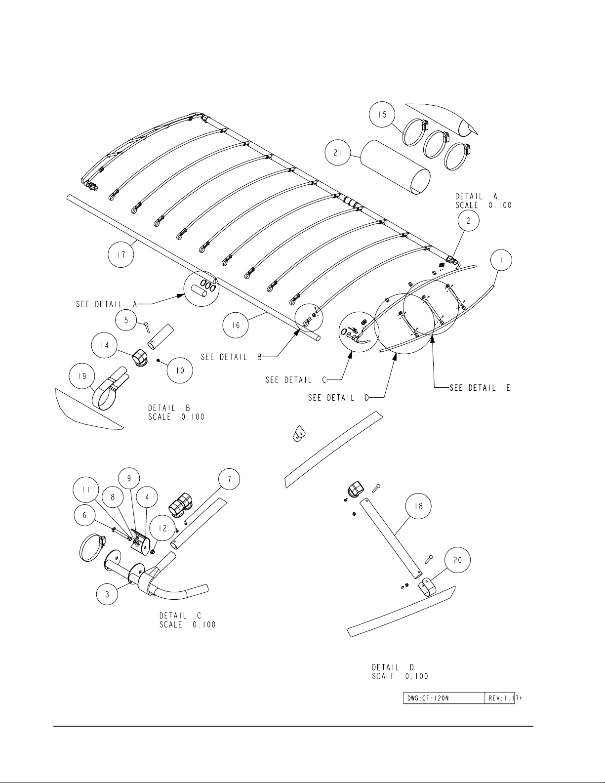
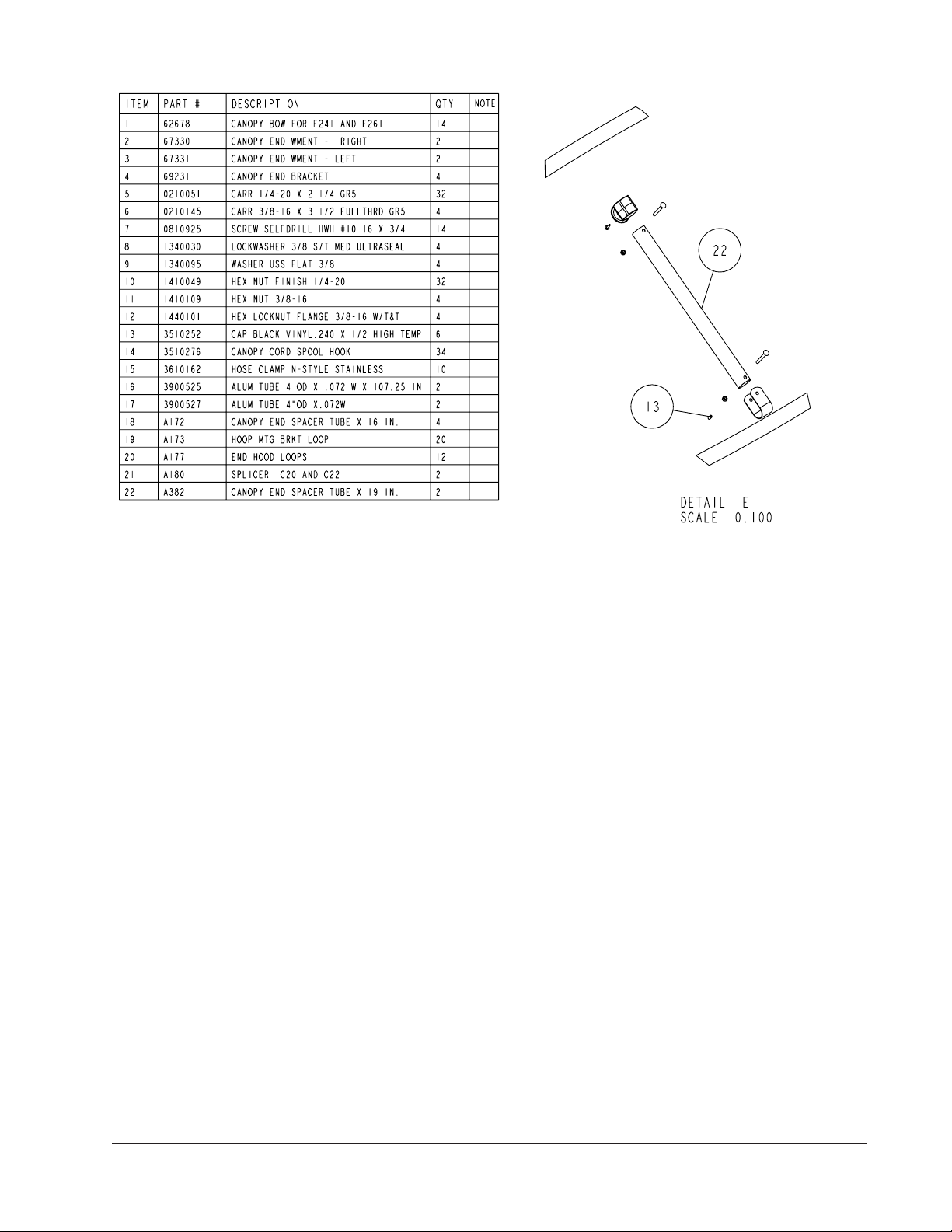
Diagram B
Midwest Industries, Inc. Ida Grove, IA 51445 800.859.3028 www.shorestation.com 0003526
Page 2 REV A 4/12/06
ASSEMBLY INSTRUCTIONS
Break bundles and hardware box. Sort all parts according to
size. Depending on the model ordered, you may have extra
parts.
END HOOD ASSEMBLY
(Refer to Diagram A for a final assembly view)
The first step will be to assemble the end hoods. Locate
the adjustable canopy end assemblies. Note that there are
two- right and two- left hand assemblies. (See Diagram B,
Detail E.)
Next locate two of the canopy bows and place them on the
floor or ground with one each of the right and left hand assemblies placed at each end of the bows.
Identify the canopy bow that will be installed as the bow that
will form the upper curved portion of the canopy end section.
Slide two (2) each of the plastic canopy cord spool hooks on
each end of this canopy bow. A total of four canopy cord spool
hooks will be placed on this bow.
Insert one end of the two canopy bows over the round tubes
on one of the adjustable canopy end assemblies. Note that
one bow will lay flat on the floor while the other bow with the
canopy cord spool hooks installed will curve upward in the
form of the canopy once it is completely assembled.
Insert the other ends of the canopy bows onto the round tubes
on the second adjustable end assembly. Make sure that the
canopy bows are slid onto the round tubes as far as they can
without jamming or driving them on.
Mark the centers on the two canopy bows. Locate one of the
19” canopy end spacer tubes (Item 22 in Diagram B, Detail
E). Attach it to the canopy bow that is laying flat on the floor
or ground at the center location just marked. Secure together
with an end hood loop using a 1/4” x 2-1/4” carriage bolt and
nut provided as shown. Slip one of the canopy cord spool
hooks onto the 19” canopy end spacer tube. Secure the
other end of the spacer tube to the top bow with a second
end hood loop and 1/4” x 2-1/4” carriage bolt. Secure with a
¼” hex nut. Tighten.
Locate one of the 16” canopy end spacer tubes (Item 18 in
Diagram B, Detail D). Attach it to the canopy bow that is laying
flat on the floor or ground at the ¼ point (center between the
end of the canopy bows and the 19” spacer tube just installed
in the center). Secure together with an end hood loop using
a 1/4” x 2-1/4” carriage bolt and nut provided as shown. Slip
one of the canopy cord spool hooks onto the 16” canopy
end spacer tube. Rotate the spacer tube up and slide either
towards or away from the 19” center spacer tube until it will
fit between the two canopy bows. Secure the other end of the
spacer tube to the top bow with a second end hood loop and
1/4” x 2-1/4” carriage bolt. Secure with a ¼” hex nut. Tighten.
Repeat on the other side of the end hood assembly.
Locate the ½” long black plastic caps supplied in the hardware. Push one of them onto each of the bolts sticking
through the nut securing the spacer tube to the flat canopy
bow. This will protect the vinyl cover from fraying when it
comes in contact with the bolt.
Measure up and place a mark at 7 ½” and 10 ½” from each
end of the upper canopy bow forming the top curve. Place
the mark on the bottom side of the tube.
Midwest Industries, Inc. Ida Grove, IA 51445 800.859.3028 www.shorestation.com 0003526
Page 3 REV A 4/12/06

Locate a No. 10 x ¾” self-drilling screw. Position the bottom
edge of the canopy cord spool hook on the 10 ½” mark. Position so the spool of the molding is pointing directly down.
Secure in this position by placing the self-drilling screw into
the center hole of the spool, then drilling the screw in to attach
it to the canopy bow.
Place the bottom edge of the second canopy cord spool
hook at the 7 ½” mark. Position so the spool of the molding
is pointing directly down. Secure in this position by placing
the self-drilling screw into the center hole of the spool, then
drilling the screw in to attach it to the canopy bow.
Measure and place a mark at 2” from the top of the 19” and
the 16” canopy end spacer tubes. Locate a No. 10 x ¾” selfdrilling screw. Position the top edge of the canopy cord spool
hook on the 2” mark. Position so the spool of the molding is
pointing inward as shown. Secure in this position by placing
the self-drilling screw into the center hole of the spool, then
drilling the screw in to attach it to the canopy bow.
Repeat the above process on the other end hood assembly.
FRAME ASSEMBLY INSTRUCTIONS
Tighten the stainless steel hose clamps evenly and securely
around the side frame splice placing two of the clamps at
the very ends of the side frame splice and one in the center
of the splice where the ends of the side frame tubes meet
inside the splice.
The frame is easiest assembled when it is assembled on
four sawhorses or something of this height. Place the two
sideframe tubes on the sawhorses located at a spacing that
is comparable to the width of the canopy once it is assembled.
Place the two side frame tube assemblies so the splicers are
directly across from each other (long side frame tubes are at
same end of canopy). Insert the two end hood assemblies just
assembled into the ends of the 4” diameter side frame tubes.
This will properly space the tubes and keep them positioned
while the balance of the bows are assembled to the side
frames. Make sure the adjustable end hood assemblies are
slid completely in and against the end of the side frame tube.
Secure in this position by placing a stainless steel hose clamp
around the side frame tube and also around the end hood
tube stop weldment approximately 1” from the end of the side
frame tube. Position the tightening mechanism on the clamp
so it is located on the inside of the side frame tube and in a
position that won’t interfere with the canopy cover when it is
pulled around the side frame tube during installation.
Locate the four 4” side frame tubes. Note that there are two
different lengths. Identify a smooth flat surface that they can
be laid on during assembly because it makes the process
much easier to accomplish. Measure and place a mark at 6”
from one end of each of the side frame tubes. Loosen four
of the stainless steel hose clamps large enough so they will
slide over the side frame splice, Ref. 20 in Detail B. Mate the
marked ends of a short and long side frame tube together.
Slide the splice onto the first side frame tube until it meets
the 6” mark. Place the second side frame tube into the splice
until the ends of the side frame tubes are touching each other.
Note: The side frame tubes nudged together is very important
because it adds considerable strength to the joint once it is
fully assembled and tightened properly. The ends of the side
frame tubes must be centered in the splice.
Repeat the process on the other side frame tube.
The canopy bows are to be spaced on 24” centers. Using
a tape measure, place the first mark at 22”. Then mark The
balance of the side frame 24” intervals the full length of the
side frame tubes.
Locate the balance of the canopy bows. Slide two (2) each
of the canopy cord spool hooks on each bow, then attach
them to the side frames using the hoop mounting bracket
loops provided.
Note that they have to be formed around the side frame tube
when assembling. Align the hole in each end of the hoop
mounting loop with the holes in the end of the canopy bow.
Secure together using 1/4” x 2-1/4” carriage bolts and hex
nuts. Thread on the nuts but do not tighten until instructed.
Repeat the above process on all of the canopy bows. Once
they are all attached to the side frames, relocate them so they
are on the 24” marks identified earlier.
Midwest Industries, Inc. Ida Grove, IA 51445 800.859.3028 www.shorestation.com 0003526
Page 4 REV A 4/12/06
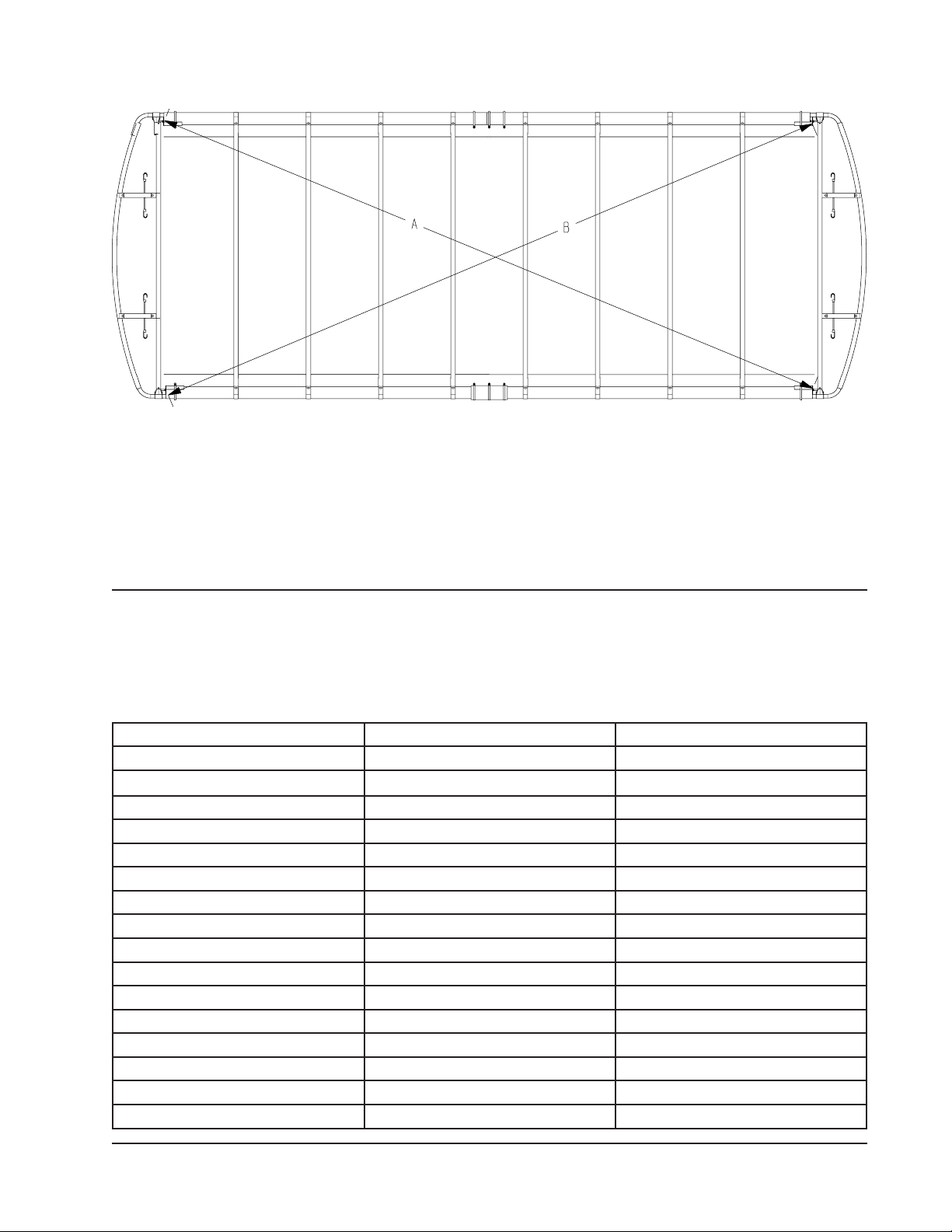
CHECKING FOR CANOPY FRAME SQUARE
Diagram AA
Check for square by using a tape measure or string.
Measure from one end of the side frame tube on one side of
the framework to the other side frame tube on the other side
of the framework.
Pull a tape measure or string from the opposite ends of the
canopy side frames across the framework as shown in the
above diagram.
Measurements A and B must match each other in order for
the framework to be square. If they don’t, slide one side frame
either forward or backward until matching measurements are
achieved. Once achieved, tighten all of the bolts attaching the
canopy bows to the side frames. the framework assembly is
now complete.
The canopy post assembly and installation instructions are supplied with the canopy post bundles and are located in the
support cup box. Use these instructions to attach the canopy posts to your hoist.
The following canopy post bundles are required to fit the following hoist.
Once the canpo y posts have been installed on your hoist continue to attach the cano py frame and vinyl as
follows.
Hoist Model Canopy Post Required Consists of Bundles
SSV30120 CP72D 68318, 68324
SSV40120 CP72D 68318, 68324
SSPV30120 CP72D 68318, 68324
SSPV40120 CP72D 68318, 68324
SSV30120DW CP30D 68318, 68325
SSV40120DW CP30D 68318, 68325
SSPV30120DW CP30D 68318, 68325
SSPV40120DW CP30D 68318, 68325
SSV40120HYD CP72K 68317, 68331
SSV50120 CP72M 68318, 68330
CP90F 68318, 68327
SSV50120DW CP32M 68318, 68329
SSV60120HYD CP72H 68317, 68332
CP90H 68317, 67567
SSV60120HYD DW CP32H 68317, 67320
SSV45120 (Steel Hoist) CP42G 68320, 68328
Midwest Industries, Inc. Ida Grove, IA 51445 800.859.3028 www.shorestation.com 0003526
Page 5 REV A 4/12/06
 Loading...