

BULLETIN NO.IM130/02
(Supersedes IM130/01)
®
Model 130
Installation and Operating Instructions
INSPECTION
Before installation check nameplate on each
instrument against the receiving paperwork and the
intended application for correct part number,
materials, working pressure, dial range, etc. If
equipped with switches, check electrical rating,
type of enclosure, etc.Inspect for shipping damage.
If damaged, report it immediately.
NOTE - Before attempting repairs contact your
local Mid-West Representative or our
factory. Failure to do so will void any
warranty.
PR
ODUCT DESCRIPTION
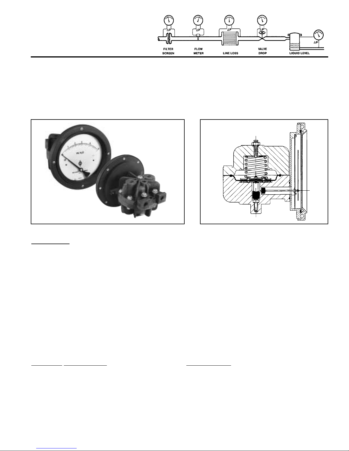
The Model 130 is a differential pressure instrument
available as a switch, gauge, or both. See “Part
Numbering System”, (Fig. 2).
A flexible elastomer diaphragm and calibrated
range spring are moved by differential pressure. A
magnet, coupled with the diaphragm, transmits
motion through the wall of the pressure housing to
a follower magnet attached to an indicating pointer.
The rotation of the follower magnet causes the
pointer to track movement of internal magnet and
indicate differential on the dial scale.
When equipped with switches for Aluminum, Brass
or 316SS bodies only, a contact is made or broken
by the magnetic field of the internal magnet.
The diaphragm is totally supported upon reaching
full travel in either direction, providing full overrange protection to rated working pressure.
INST
ALLATION
Model 130 is calibrated and tested prior to
shipment and is ready for immediate installation.
Use of the following installation procedures should
eliminate potential damage and provide optimum
trouble-free operation.
Mid-West
Instrument

NOTE - It is highly recommended that a three
valve manifold be installed in the
instrumentation loop to minimize
possible damage during pressurization.
1. CONNECTIONS
Model 130 P is provided with 1/4" compression
tube fittings, one low and one high, on the top
and bottom of gauge body.
Model 130 A, B, H, S, is provided with dual 1/4"
FNPT connections top and bottom as standard.
One pair of high and low pressure ports is for
process connections. The other pair is plugged or
used as drain/bleed connections.
Ports are identified for high and low pressure. Be
sure to plumb to proper connections on system.
Improper connection will not damage instrument
but it will not function properly.
Flexible tubing is recommended to minimize effect
of any vibration that may exist.
When attaching connections to the 130 P, care
must be taken to prev ent o v er-tightening which ma y
result in stripping threads and/or cracking ports. In
order to prevent this, use a suitable wrench to hold
the factory supplied fitting in place while tightening,
sometimes called “double wrenching”.
2. INSTRUMENT LOCATION
On liquid service, the instrument should be
mounted below the process connections to
facilitate self-bleeding.On gas service, it should be
located above the process connections to promote
self-draining. If the process contains particulates, a
“pigtail” loop or drop leg (manometer “U-tube”
configuration) in the tubing will minimize the
possibility of it migrating into the instrument.
NOTE - On liquid applications, unequal liquid
heads on high or low side will result in
an inaccurate differential pressure
indication.
3. PANEL MOUNTING
The Model 130 is designed for mounting through
the front of the instrument panel and is provided
with a panel mount kit, consisting of (4) panel
mounting studs/nuts.
Make cutouts as indicated in (Fig. 1). Insert (4) panel
mounting studs, finger tight, into metal inserts located
in the rear of the bezel.
Insert gauge through the panel, aligning panel
mounting studs with holes in the panel. Install #832 nuts onto studs and tighten securely.
4. PIPE MOUNTING
If specified, your Model 130 will have a pipe mount
kit installed. This provides for mounting on a 2"
vertical or horizontal pipe. See (Fig. 1).
5. ELECTRICAL - See Mid-West Bulletin
IMELEC130/latest
TR
OUBLE SHOOTING
1. Gauge does not indicate differential.
A. Check for proper hook up, high to “hi” and
low to “lo”.
B. Make certain block valves are open and, if
using a 3-valve manifold, that the equalizer
(balance) valve is closed.
C. If A & B check out, loosen high pressure line
to determine if there is pressure to
instrument.
D. If there is pressure to instrument, check to
determine that there is differential across the
unit being monitored.If so, contact factory for
assistance and/or an “RGA” (return goods
authorization) number to return instrument
for repair or replacement.

MOUNTING INFORMATION & DIMENSIONAL DATA
(FIG. 1)
NOTES: 1. Drawings show standard gauge nominal dimensions. (not to scale)
2. Dimensions shown in parentheses are in millimeters.
3. Add to panel cut out for condulet/switch assembly option.
MODEL 130 - P
MODEL 130 A - 130 B - 130 H - 130 S
Manufacturer reserves the right to change specifications without prior notice.
Temperature limitations: -40°F(-40°C) to +200°F (+93°C). Proof pressure: two times rated working pressure.
NOTE: These limits are based on the entire instr ument being saturated to these temperatures. Systems (process) temperatures
may exceed these limitations with proper installation.Contact our customer service representative for details.
STANDARDS: All Model 130 Ser ies differential pressure gauges either confor m to and/or are designed to
the requirements of the following standards:
ASME B1.20.1 NACE MR0175
ASME B40.1 NEMA Std. No. 250
CSA-C22.2 No.14.25 and 30 SAE J514
EN-61010-1 UL Std. No. 50,508 and 1203
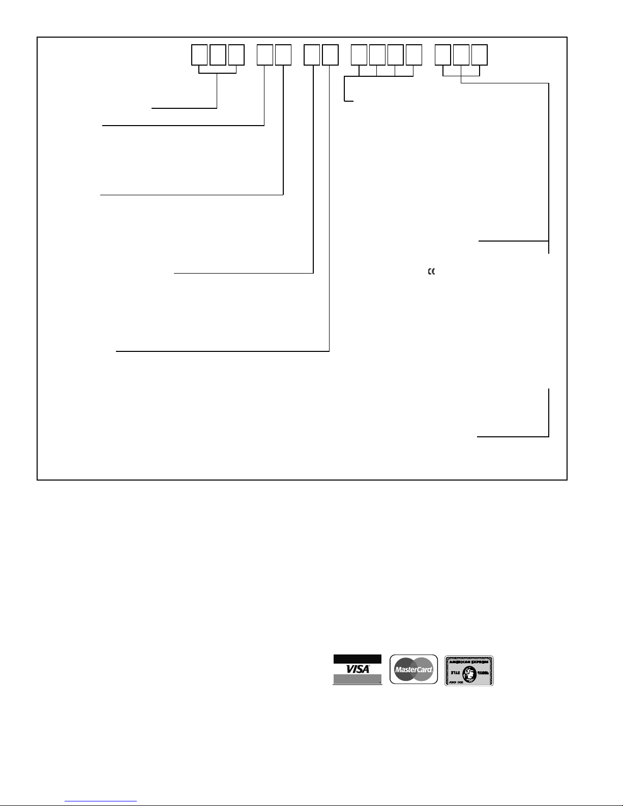
PART NUMBERING SYSTEM
6500 Dobry Dr. ■■ Sterling Heights, MI 48314 U.S.A.
(586) 254-6500
■■ FAX (586) 254-6509
E-mail: sales@midwestinstrument.com
Website: www.midwestinstrument.com
Printed in U.S.A.
REPRESENTED BY:
(FIG. 2)
BASIC MODEL NUMBER
➀
MATERIAL
➁
A. Aluminum
B. Brass
H. Hastelloy C
P. Glass-Reinforced Engineering Plastic Body
S. 316 S.S.
Z. Special (Uncoded Options)
DIAL SIZE
➂
C. 4-1/2" Round Dial Engrd. Plastic Housing Assy. (STANDARD)
E. 3-1/2" Round Dial Anod. Aluminum Housing Assy.
G. 4-1/2" Round Dial Anod. Aluminum Housing Assy.
T. Non-Indicating Differential Pressure Switch Only
(Select Appropriate Electrical Options)
Z. Special (Uncoded Options)
SEALS & DIAPHRAGM MATERIAL
➃
0. Buna N (STANDARD)
1. *Viton®
2. Silicone
5.
Ethylene Propylene
9. Special (Uncoded Options)
*Viton® is a Registered Trademark of DuPont Dow Elastomers.
CONNECTIONS
➄
0. 1/4" C.S.Comp.Tube Ftgs.(2) Model P or 1/4" FNPT (4) for Models A, B & S (STANDARD)
1. 1/4" 316 S.S.Comp.Tube Ftgs.(2)
2. 1/4" FNPT Brass Adapters (2) (Model P Only)
3. 1/4" FNPT 316 S.S.Adapters (2) (Model P Only)
4. 1/2" FNPT 316 S.S.Adapters (2) (All Models, Except P)
9. Special (Uncoded Options)
(0-5" H2O thru 0-100" H2O max)
1 3 0 – – –
–
OPTIONS (Up to four options)
➅
O. None (STANDARD)
B. Drain & Bleed Plugs, 316 Stainless Steel (2) (Model 130 P only)
D. Drain & Bleed, for Model 130 P in Nema 4X Enclosure
E. Drain & Bleed, for all other Model 130’s in Nema 4X Enclosure
F. Pipe Mounting Kit
H. Hastelloy C Internal Wetted Metal Parts and Fittings
M. Maximum Indicator Follower Pointer
T. Oxygen Cleaning
U. S.S.Tag Mounted w/S.S. Wire
V. S.S.Tag Mounted w/S.S.Screws
W. Wall Mounting Kit
Z. Special (Uncoded Options)
ELECTRICAL CONFIGURATIONS
➆
(SWITCH ADJUSTABLE RANGE 10-90%)
(NOTE: Switch option not available for 130-PC Models)
(NOTE: All options marked, except N & P)
O. None (STANDARD)
H. (1) Reed Switch with Condulet Enclosure
I. (2) Reed Switches with Condulet Enclosure
J.
(1) Reed Switch with Condulet Enclosure and Plug-In Connector
(DIN 43650-PG 11)
K.
(2) Reed Switches with Condulet Enclosure and Plug-In Connector
(DIN 43650-PG11)
L. (1) Switch in NEMA-4X Plastic Enclosure
M. (2) Switches in NEMA-4X Plastic Enclosure
N. One (1) Switch in Explosion Proof Enclosure with Glass
Window Cover and C.S.A. Listing
P. Two (2) Switches in Explosion Proof Enclosure with Glass
Window Cover and C.S.A. Listing
Z. Special (Uncoded Options)
(1)
Complete Assembly Rated Class I, Division I, Groups C & D;
Class II, Division I, Groups E, F & G.
(1)
(1)
– (Up to three options)
➆ ➇
NOTE: The use of diaphragm seals is not recommended for the model 130 series gauges.
Attempts to install such seals will void the warranty.
NOTE: Not all options available in combination with other options.
ELECTRICAL SPECIFICATIONS
➇
(For Resistive Loads)
A. SPDT, 3 Watts, 0.25 Amp, 125 VAC/VDC (Switch adjustable range 10-90%)
Z. Special (Uncoded Options)
®
Mid-West
Instrument
 Loading...