

Mid-West 116 DPI Installation And Operating Instructions Manual
BULLETIN NO. IM116DPI/08
®
Mid-West Instrument
INSPECTION
Before installation carefully check the Model Number on
each instrument against the receiving paperwork and
the intended application. Inspect for shipping damage
and, if damaged, report it immediately. Verify when
the unit is unpacked and in a vertical position that the
pointer is on zero. If the pointer is off zero see
TROUBLE SHOOTING
on zeroing the pointer.
NOTE: BEFORE ATTEMPTING REPAIRS
CONTACT YOUR LOCAL MID-WEST
REPRESENTATIVE OR OUR FACTORY.
FAILURE TO DO SO WILL VOID ANY
WARRANTY.
Installation and Operating Instructions
section 2 for instructions
Model 116 DPI
,
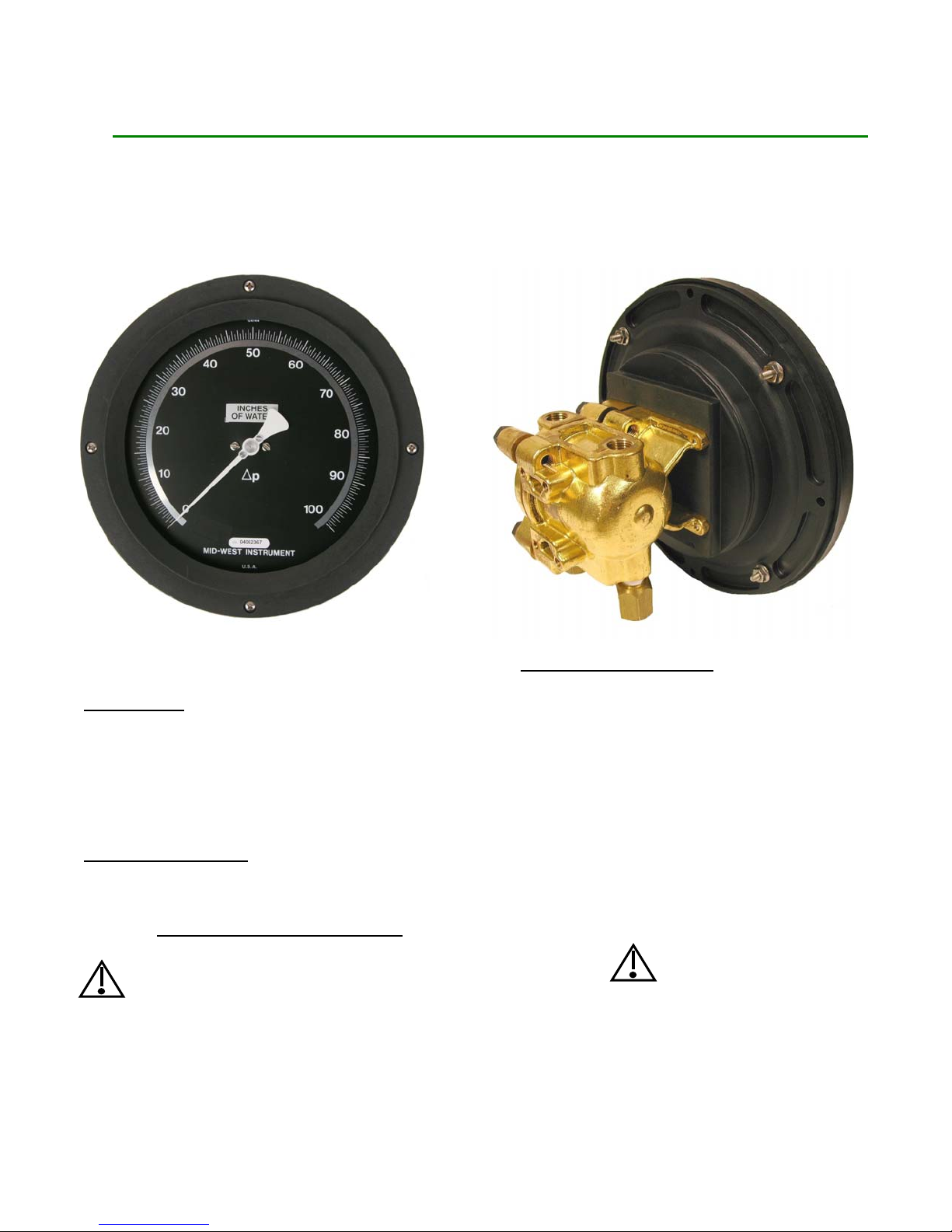
PRODUCT DESCRIPTION
The Model 116 design for cryogenic applications are
all-metal differential pressure gauges capable of
operating at low differential pressures for up to 500
PSI of line pressure.
The DPI is equipped with a Bi-directional Over Pressure
Relief Valve (OPV). When the Differential Pressure
exceeds 130% of the range the OPV equalizes the
pressure between the Hi and Lo sides. Dual top and
bottom connections are provided as standard. The DPI
is also equipped with a pointer zero “micro-adjust”. If
necessary the pointer can be re-zeroed.
CAUTION:
Rapid pressurization can cause severe damage
to the sensing element. Rapid pressure change
(either increase or decrease) is a change in
pressure occurring fast enough to drive the
instrument full scale in one (1) second or less.
See installation portion of this I.O.M. for
guidance in how to prevent rapid
pressurization.

INSTALLATION
Model 116 gauges are calibrated and tested prior to
shipment and are ready for immediate installation.
Use of the following installation procedures should
eliminate potential damage and provide optimum
trouble free operation.
1. CONNECTIONS
Dual ¼” FNPT connections, top and bottom, are provided
as standard but check paperwork for connections
ordered. They are identified “high” and “low”, for high
pressure and low pressure. Be sure that one “high” and
one “low” pressure connection gets plumbed to the
proper connection on your system. The other two ports
should either be plugged or plumbed as drains or bleeds,
depending on whether the service is liquid or gas.
NOTE: It is strongly recommended that a
3-valve manifold be used in plumbing
your model 116 to your system. Properly
used it should insure that your instrument
is not over-ranged or damaged by
pressure shocks during pressurization. It
will facilitate later zeroing, ranging and
calibration checking. It is good practice to
purge or flush the instrument loop prior to
connecting the instrument.
When pressurizing the instrument have
the bypass valve open. Slowly open the
high side and low side isolation valves.
When the unit is pressurized close the
bypass valve to obtain a DP reading.
When removing the instrument open the
bypass valve prior to closing the high side
and low side isolation valves. Leave the
bypass valve open when venting the
instrument.
2. PANEL MOUNTING
The Model 116 is designed for mounting through the
front of the instrument panel and is normally provided
with a panel mounting kit.
Make the cutouts as indicated in (Figure 1). Insert the
gauge through the panel aligning the panel mounting
studs with the holes in the panel. Install the nuts onto
the studs and tighten securely.
TROUBLE SHOOTING
1. Gauge does not indicate differential.
A. Check for proper hook up, high to high and low
to low.
B. Make certain that block valves are open and, if
using a 3-valve manifold, that the equalizer
(balance) valve is closed.
C. If A and B check out correctly, loosen or
disconnect the high pressure line to determine if
there is pressure to the instrument.
D. If there is pressure to the instrumen t, check to
determine that there is a differential across the
unit being monitored. If there is, contact the
factory for assistance and for an “RGA” (returned
goods authorization) number to return the
instrument for repair or replacement.
2. Indicating pointer off zero. (With block valves
closed, equalizer valve open, or no system
differential.)
A. Tap gauge lightly.
B. Make certain block valves are closed and
equalizer valve is open.
C. If A & B do not correct the “off zero” condition,
remove the bezel and lens assembly by removing
the (4) bezel screws. Grasp the pointer hub
between the thumb and forefinger. Using a
straight blade screw driver adjust the screw on
the pointer clockwise to adjust the pointer
upscale or counter clockwise to adjust the pointer
downscale. Tap the gauge lightly to confirm the
pointer is on zero. Reinstall the bezel and lens
assembly.
RECALIBRATION AND/OR REPAIR
1. If recalibration or repair is required, secure an
“RGA” (returned goods authorization) number
from Mid-West Instrument and return the
instrument to the factory.
2. If (1) is not practical, we recommend you discuss
your problem with one of our customer service
representatives and request a “technical service”
manual. Please have both the model and serial
numbers available before calling
 Loading...