

Mid-West 105 Locked Logic, 106 Locked Logic, 109 Locked Logic Installation And Operating Instructions Manual
BULLETIN NO. IMLLC/0
4
Replaces ELEC-IMLLC/02
Mid-West
ELECTRICAL SPECIFICATIONS
®
Instrument
INSPECTION
Before installation carefully check the "Electrical
Specifications" plate (See Fig. 1) on each instrument against
the receiving paperwork and the intended application for the
correct input and output. Make certain that the enclosure
(NEMA 4 or NEMA 7) is appropriate for the area in which it is
to be installed. Inspect for shipping damage and, if damaged,
report it immediately. Verify when the unit is unpacked and in
a vertical position that the pointer is on 0.
Model 105 /106 & 109 “Locked Logic”
Installation and Operating Instructions
NOTE: BEFORE ATTEMPTING REPAIRS,
CONTACT YOUR LOCAL MID-WEST
REPRESENTATIVE OR OUR
FACTORY. FAILURE TO DO SO WILL
VOID ANY WARRANTY.
INPUT: 8-28 VDC 115 VDC
115 VAC 50-60 HZ 230 VAC 50-60 HZ
OUTPUT (RESISTIVE LOAD):
10 A, 28 VDC
10 A, 115/240 VAC 50-60 HZ
FIG. 1: ELECTRICAL SPECIFICATION PLATE
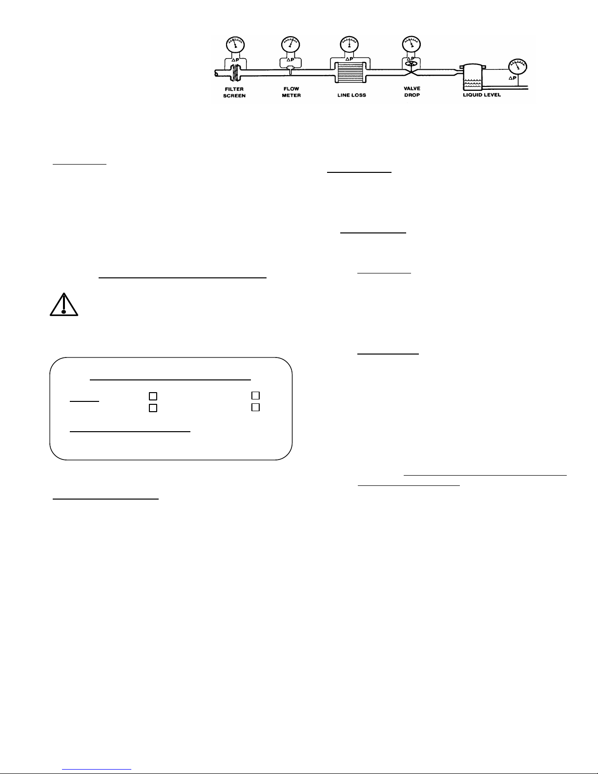
PRODUCT DESCRIPTION
"Locked Logic" alarm control is a solid-state optical-electronic
control available as an option on Mid-West Models 105/106
and 109 differential pressure gauges. The control is an
optical "no-contact" design that does not affect the indicated
accuracy of the instrument.
The standard unit is designed for an 8 to 28 VDC
uninterruptable power input. Optional power inputs include
115 VDC, 115 VAC 50-60 hertz, or 230 VAC 50-60 hertz.
Output interface is via a set of (1) or (2) isolated SPDT or
DPDT relay contacts, dependent on the number of set points
specified. Interface to the relay contacts is customer
configurable provided the relay contact ratings are not
exceeded.
An alternate option allows the incorporation of an
adjustable dead band. For this configuration the right set
pointer determines the upper trigger point, while the left set
pointer determines the lower trigger point. Output interface is
to (1) isolated set of SPDT relay contacts.
INSTALLATION
All Mid-West "Locked Logic" alarm-controls are calibrated
and tested prior to shipment and are ready for immediate
installation.
1. Panel Mounting - Both weatherproof and explosion-proof
models may be panel mounted. See Fig. 2 for panel
cutout information.
A. Weatherproof - This unit mounts through the front of
the panel. After making the panel cutout insert the
(4) panel mounting studs, finger tight, into the (4)
tapped holes in the rear of the housing. Insert the
gauge through the panel, aligning the panel mounting
studs with the holes in the panel. Install the (4) #8-32
nuts onto the studs and tighten securely.
B. Explosion-proof –
WARNING: THE COVER MUST NEVER BE
REMOVED WHEN THERE IS POWER TO THE
UNIT.
Normally pipe mounted, this unit may also be panel
mounted through the front of the panel. Unless
otherwise specified, your explosion-proof unit will be
provided with a pipe mounting kit. To panel mount,
remove the pipe mounting kit by removing the (4) hex
headed 1/4 - 20 bolts attaching it to the back of the
enclosure. Save the (4) bolts and washer for use
in mounting to the panel. Refer to Fig. 2 for panel
cutout information. Once the appropriate cutout is
made, mount the unit through the front of the panel
and install the (4) 1/4 - 20 bolts and washers from the
back of the panel and into the enclosure. Tighten
securely.
You may now proceed with plumbing and wiring the
unit into your system.

2. PIPE MOUNTING - (See Fig. 2 for mounting instructions.)
WEATHERPROOF – Pipe mounting is an optional extra
for Models 105, 106 & 109 “Locked Logic” units.
EXPLOSION-PROOF - A pipe mounting kit is provided as
standard for all Model 105, 106 and 109 "Locked Logic"
units unless otherwise specified.
3. CONNECTIONS - For plumbing the Model 105, 106 or
109 to the pressure connections on your system, follow
the instructions for that instrument. Once accomplished,
proceed with the electrical instructions that follow.
4. ELECTRICAL - Both weatherproof and explosion-proof
"Locked Logic" enclosures have an opening, top rear, for
a ½” or ¾” flexible cable or conduit connector. An
appropriate connector must be installed before making
connections to the wire leads provided. See the wiring
interface drawing provided with your gauge for proper
electrical connections to the gauge.
For Units supplied with both AC and DC input power
leads, do not accidentally connect AC power to the DC
leads. The unit will be damaged
CAUTION: FOLLOW ALL ELECTRICAL CODE
REQUIREMENTS FOR VOLTAGE, AC OR DC SUPPLY
AND ENVIRONMENTAL CONDITIONS AS REQUIRED
LOCALLY.
NOTE: INSTALL THE FRONT COVER AND BEZEL
ASSEMBLY AFTER SWITCH ADJUSTMENT AND DO
NOT LEAVE THE UNIT OUTDOORS WITHOUT A
CONNECTOR IN THE ELECTRICAL OPENING OR THE
UNIT MAY BE DAMAGED FROM ENVIRONMENTAL
CONDITIONS.
5. SETPOINT ADJUSTMENT - Set pointers are adjustable
from 5 to 95% of full scale and to within 5% (of full scale)
of each other if equipped with (2) set pointers. The
adjustment screws are inside the enclosure to protect
against unauthorized adjustment. Before opening the unit
to make a set point adjustment, check plant operating
procedures and electrical codes. For weatherproof units,
remove the (4) bezel screws and the bezel assembly. For
explosion proof units, unscrew the window assembly from
the housing.
CAUTION: BE SURE POWER IS TURNED OFF
BEFORE REMOVING THE COVER FROM
(EXPLOSION-PROOF) UNITS.
Insert a screwdriver in the setpoint adjustment slot and
rotate until the setpointer is at the desired point on the
scale. Replace the bezel assembly and screws, or
window assembly.
6. START UP All "Locked Logic" set pointers, except
adjustable dead-band units, have one green and one red
state indication LED per set pointer assembly. Upon
power up of the assembly the green LED(s) shall be lit
and the output relay(s) de-energized. As the indicating
pointer moves up scale and passes a set pointer, the
green LED shall extinguish, the red LED shall be on, and
the output relay shall energize. On declining differential
the sequence shall be reversed.
For adjustable dead-band units, the left set pointer has 1
green and 1 red state indication LED. The right set
pointer has no indicators. Upon power up of the
assembly the green LED shall be lit and the output relay
shall be de-energized. As the indicating pointer moves
up scale and passes the Right set pointer, the green LED
shall extinguish, the red LED shall be on, and the output
relay shall energize. On declining differential (indicating
pointer moves downscale), the red LED shall extinguish,
the green LED shall be lit, and the relay shall de-energize
when the indicating pointer passes the left set pointer.
Please note that these units use a reflective optical
sensor that is sensitive to infrared light. Sunshine is a
source of infrared. If the unit is placed outdoors, it is
recommended, although not necessary, to either shade
the unit or position the gauge so that the glass faces in
either a East or West direction. In extremely rare cases
the unit has triggered due to bright sunlight conditions.
For this occurrence a tinted glass is available to correct
this problem.
TROUBLE SHOOTING - SYMPTOM(S)
1. GAUGE DOES NOT INDICATE DIFFERENTIAL. Check
trouble shooting procedures in the appropriate gauge
manual and proceed accordingly.
2. L.E.D.'S DO NOT COME ON WHEN POWER IS
TURNED ON. Check wiring diagram (Fig. 1) and wiring
to make certain that all connections are properly and
securely made. Also check to make certain that the
proper power input is being provided.
3. UNIT “ALARMS” INADVERTENTLY. Check for sunshine
condition described above. Make necessary adjusments
and re-test.
3. If 1, 2, or 3 do not resolve the problem contact one of our
factory customer service representatives for assistance
and or a RGA (Return Goods Authorization) number and
return the instrument for repair or replacement.

Specification
Input Voltage: Standard Range: 8 to 28 Vdc Select one of four input ranges.
Optional: 110 to 170 Vdc
85 to 165 Vac
153 to 345 Vac
Reverse Polarity 8 to 28 Vdc Input Polarity Protected
AC units Not Applicable
Power Loss: < 0.5 seconds For loss of input power of less
than 0.5 seconds unit will
remember last state of output(s).
Logic Reset > 1 seconds To Reset logic, power must be
off for greater than 1 second
before re-application input power
Input Current: DC Inputs: 400 ma.maximum Steady State Values
AC Inputs: 100 ma maximum
Set Pointers: Quantity: 1 or 2
Adjust: 5% to 95% of Full Scale
Set 1 to Set 2 Diff.: 5 % of Full Scale (Nominal) 2 set point units only
Output(s): Contact(s): 1 or 2 SPDT or DPDT
Contact Rating: 10 Amps Maximum @ 30 VDC
10 Amps maximum @ 115/240 VAC
Temperature: Operating: -40F to +160 F / -40 C to +70 C
Environment: Standard: Weather-proof Housing NEMA 4
Optional: Explosion-proof Housing Class I,Groups B,C & D
Class II, Groups E,F, & G
Electrical: Standard: 2 Ft., 18 Awg., 600V, 105 C, ½” FNPT for 1 or 2 SPDT Outputs and
Interface color coded wire leads 1 DPDT Output. ¾” FNPT for 2 DPDT
Outputs.
Optional Flexible metal conduit
Weatherproof flexible metal conduit
Extra lengths of either of above
Drawings: 101384 8-28 VDC Input, SPDT Output
107882 120/240 VAC Input, SPDT Output
108047 AC Input, 1 DPDT Output
108158 AC Input, 2 DPDT Output
108479 DC Input, 1 DPDT Output
108736 DC Input, 2 DPDT Output
Materials of Weatherproof: Cast Aluminum with "engineering plastic" bezel
Construction Explosion Proof: Cast Aluminum
MANUFACTURER RESERVES THE RIGHT TO CHANGE SPECIFICATIONS WITHOUT PRIOR NOTICE
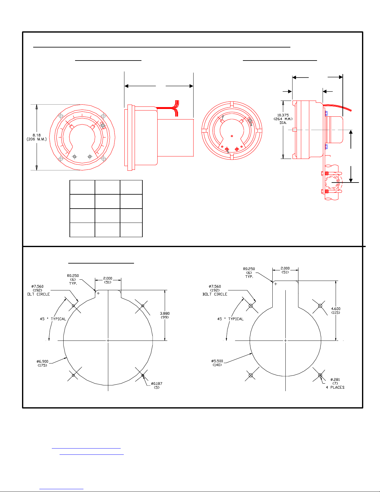
FIGURE 2: MOUNTING INFORMATION & DIMENSIONAL DATA
WEATHER PROOF
MODEL A B
105
106
109
7.73
(196.3)
7.25
(184.1)
6.50
(165.1)
8.86
(225.0)
8.38
(212.8)
7.63
(193.8)
PANEL CUT-OUTS
WEATHER PROOF EXPLOSION PROOF
Mid-West
Instrument
6500 Dobry Dr. Sterling Heights, MI 48314
(586)254-6500 FAX (586)254-6509
E-Mail: sales@midwestinstrument.com
Web Page: www.midwestinstrument.com
A
4 Places
EXPLOSION PROOF
B
5.13
(130)
7.88
(200.3)
 Loading...