

Page 1

MARCH 2000
16-80020-101
®
TOUCHSCREEN VIDEO
GAME MACHINE CONVERSION
FOR USE ON THESE CABINETS
Manual Includes
• Installation • Operations • Adjustments • Par t s I nformation • Wiring • Troubleshooting •
The manufacturer intends that this game is to be operated for amusement purposes only and not in contravention of
any federal, state or local law or regulation of the United States or any foreign country governing gaming devices. All
operators of this game are responsible for its operation in accordance with such laws and regulations. The
manufacturer’s factory settings for this game may require adjustment in order to comply with laws applicable in an
operator’s specific jurisdiction. It is the operator’s responsibility to determine whether adjustments are necessary
and, if they are, to make the appropriate adjustments prior to operating the amusement game.
MIDWAY AMUSEMENT GAMES, LLC.
3401 North California Avenue Chicago, Illinois 60618-5899 USA
http://www.midway.com
Page 2
How to adjust the volume of your Touchmaster® VGM:
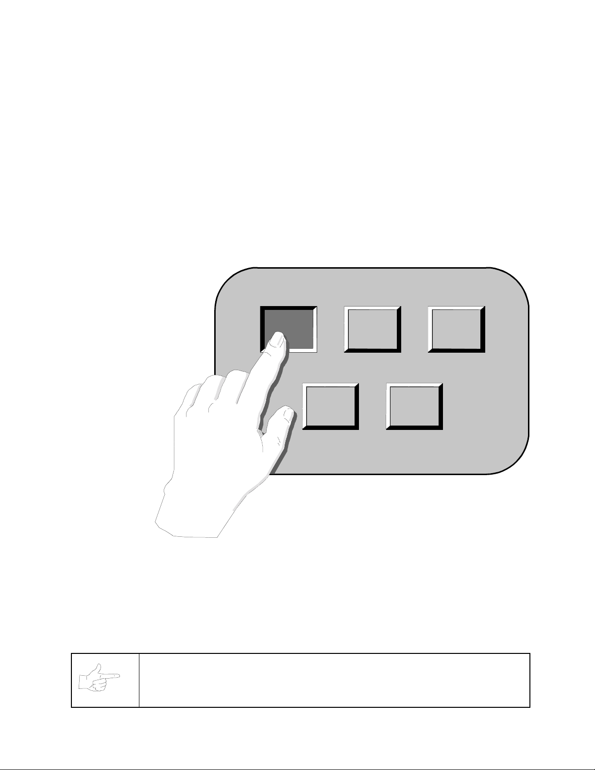
SYSTEM SETUP
VER : X.XX XXXXX XX/XX/XX
GAME-COIN
SETUP
DISPLAY
AUDITS
HIGH
SCORES
LOCATION
SETUP
V
O
L
U
M
E
DIAGNOSTIC
+
EXIT
-
CASH DOOR
SETUP BUTTON
OPERATOR
MESSAGE
ENGLISH ESPANOL
FREEPLAY
FREE
CREDIT
Illustration A. Setup Button Location Illustration B. SYSTEM SETUP screen
1.
Remove cash door and hit SETUP button. (See Illust. A.)
2.
Touch + or – button to adjust volume level. When done, touch EXIT button. (See Illust. B.)
3.
Replace cash door. (See Illust. A.)
How to customize your Touchmaster® VGM name:
1.
Remove cash door and hit SETUP button. (See Illust. A.)
2.
Touch LOCATION SETUP button on screen. (See Illust. B.)
LOCATION SETUP
YOUR CUSTOMIZED NAME
LOCATION
NAME
TOUCH KEY
SETUP
SERIAL NO
SETUP
CLEAR SPACE DELETE SHIFT
ENTER LOCATION NAME
_________________________
RETURN
Í
Î
UR CUSTOMIZED NAME ROLLS BY YOUR
SPEED
MED
RETURN
0
1 2 3 4 5 6 7 8 9
A B C D E F G H I J K
N O P Q R S T U V W X
L M
Y Z
Illustration C. LOCATION SETUP screen Illustration D. ENTER LOCATION NAME screen
3.
Touch LOCATION NAME button. (See Illust. C.)
4.
Touch characters of name. (See Illust. D.) Touch RETURN when done.
5.
Touch RETURN button in LOCATION SETUP screen. (See Illust. C.)
6.
Touch EXIT button in SYSTEM SETUP screen. (See Illust. B.)
7.
Replace cash door. (See Illust. A.)
Page 3
®
T
OUCHMASTER
CONVERSION
CHAPTER
1
2 3
54
ETUP
S
NOTICE:
Amusement Games, LLC reserves the right to im prove equipment function, design, or
components as progress in engineering or manufacturing methods may warrant. Field
installed upgrade kits may also change the operating sequence or functions.
Information in this manual is subject to change without notice. Midway
Page 4
SAFETY INSTRUCTIONS
The following instructions apply to operators and service personnel. Read these instructions before
preparing your Video Game Machine (VGM) for play. Other safety instructions appear throughout this
manual.
DEFINITIONS OF SAFETY TERMS
DANGER
WARNING
CAUTION
CAUTION also alerts you about unsafe practices.
NOTICE
the VGM equipment.
indicates an imminent hazard. Failing to avoid this hazard WILL cause death or serious injury.
indicates a potential hazard. Failing to avoid this hazard COULD cause death or serious injury.
indicates a potential hazard. Failing to avoid this hazard MAY cause minor or moderate injury.
indicates information of special importance. Observing notices may prevent you from damaging
WARNING: DO NOT SUBSTITUTE PARTS.
modifications could cause serious injury or equipment damage! Use only Midway
authorized parts.
For safety and reliability, do not substitute parts or modif y Midway products. Substitute
parts or modifications may void EMC directive or FCC type acceptance.
WARNING: DISCONNECT POWER.
cord before attem pting service or adjustm ents. Installing or repairing board assem blies
while the power is on can cause inj ury, damage com ponents, and void the warranty. Be
sure that you securely install ground wires.
WARNING: GROUND VGM.
have inspected and properly grounded it. Only plug this VGM into a grounded, three- wire
outlet. Do not use a “cheater” plug, or cut off the ground pin on the line cord.
WARNING: GROUND SELF.
yourself frequently by touching the metal chain lug on the rear of the cabinet to discharge
static electricity from your body.
CAUTION: INSPECT SALVAGED PARTS.
from an existing VGM. Salvaged parts must operate perf ectly for the converted VGM to
perform properly and safely. Before attempting conversion, repair circuit board
malfunctions and cabinet damage.
Use of inferior parts or VGM
Always turn AC power off and unplug the line
Avoid electrical shock! Do not plug in a VGM until you
Wear a grounding strap during installation. Ground
Kit completion requires salvaging parts
CAUTION: PROPERLY ATTACH ALL CONNECTORS.
CPU Board Assem bly are properly connected. If the connectors do not slip on easily, do
not force them . A r eversed c onnector m ay damage your VGM and void the warranty. All
wiring harness connectors are keyed to fit specific header pins on the Board Assembly.
Make sure connectors on the
EPILEPSY WARNING
A very small portion of the population has a condition which may cause them to experience epileptic
seizures or have momentary loss of consciousness when viewing certain kinds of flashing lights or
patterns that are commonly present in our daily environment. These persons may experience seizures
while watching some kinds of television pictures or playing certain video games. People who have not had
any previous seizures may nonetheless have an undetected epileptic condition.
If you or anyone in your family has experienced symptoms linked to an epileptic condition (e.g. seizure or
loss of awareness), immediately consult your physician before using any video games.
We recommend that parents observe their children while they play video games. If you or your child
experience any of the following symptoms: dizziness, altered vision, eye or muscle twitching, involuntary
movements, loss of awareness, disorientation, or convolutions,
your physician.
Setup - 2 Midway Amusement Games, LLC
discontinue use immediately
and consult
Page 5
PRODUCT SPECIFICATIONS
VGM Characteristics
Player Variables
Choice of Several Different Games
1 or 2 players per game
High Score Recognition, Difficulty
Operator Variables
Coinage, Difficulty,
Graphics, Statistics
Audits, Time, Volume
Diagnostics
Automatic Power-Up Self-Test
Manual Multi-Level Menu System
Touchscreen Calibration
MAINTENANCE
This VGM uses the same surface for video display and player controls. Because players use their fingers,
the entire screen and cabinet will quickly become covered with fingerprints. We recommend that you clean
the VGM frequently to ensure maximum customer interest.
NOTICE: AVOID ABRASIVE CHEMICALS.
bleach, lemon, vinegar, trisodium phosphate (tsp), or any abrasive ingredients. These
products can damage the surface of the touchscreen and degrade VGM performance.
Do not use products with ammonia,
♦
Glass surfaces
You may clean glass while power is on. Do not use ammonia or chlorine. Apply a mild glass cleaner to
a clean cloth or sponge, then use this to wipe screen. Do not apply the cleaner directly on the glass!
Liquids could drip down into the touchscreen circuits and cause erratic operation.
♦
Calibration
Calibrate the screen each time you clean the VGM. Use the Calibration Test steps to determine if
recalibration is required (refer to Calibration in this section).
NOTICE:
authorizes, condones, or is in any way associated with tournaments using any
Touchmaster
Neither Midway Amusement Games, LLC nor its affiliates sponsors,
®
games.
CONVERSION PROCEDURE
Pictoral presentation for experienced installers. Detailed instructions immediately follow.
Touchmaster® Conversion Kit Setup - 3
Page 6
Inspection
Unpack the materials from the carton and inspect for obvious signs of damage. Use the checklist to be
sure the kit is complete. You must supply the remainder of the materials required for this conversion.
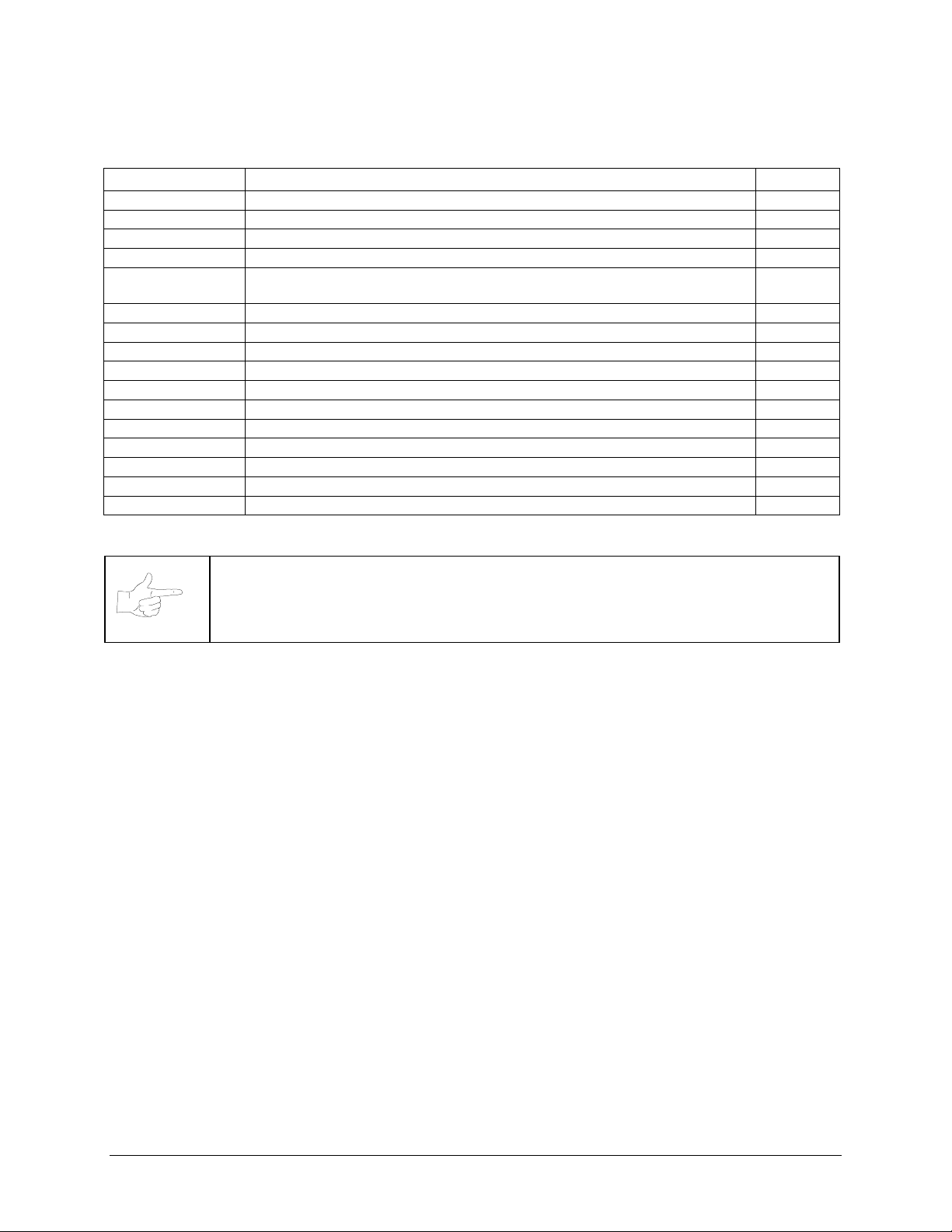
Part Number Item
[ ]
A-23380-33
[ ]
A-23381
[ ]
RM-42-01
[ ]
RM-43-01
[ ]
H-23368
[ ]
H-23379
[ ]
04-12821-1
[ ]
31-3443
[ ]
31-3444
[ ]
31-3445
[ ]
31-3458
[ ]
31-3627
[ ]
16-10089.1
[ ]
4406-01128-00
[ ]
16-80020-101
[ ]
4008-01003-05
Touchmaster
Touchscreen control module (Converts processing signal) 1
2” square of hook fastener (To fasten controller to cabinet) 1
2” square of loop fastener (To fasten controller to cabinet) 1
Wiring Harness (Connects CPU Board Assembly to speaker, video,
etc.)
Adapter Cable (Mates 15-pin to 9-pin connector, if used for cash door.) 1
Marquee Retainer with magnet fasteners. 1
Cabinet Decal-Left side (Covers existing VGM markings) 1
Cabinet Decal-Right side (Covers existing VGM markings) 1
Cabinet Decal-Front-wide (Covers wide VGM markings) 1
Cabinet Decal-Front-narrow (Covers narrow VGM markings) 1
Marquee artwork 1
Label-Epilepsy Warning (Affix to VGM front beneath monitor bevel) 1
6/32” KEPS nut (Affixes ground cable to bracket) 1
Touchmaster Conversion Kit Manual (This publication) 1
6/32” Machine Screw (Fastens CPU Board Assembly to metal plate) 6
NOTICE
standard Touchmaster
have different part numbers. The incorrect assembly will cause sync and touchscreen
calibration errors.
The conversion kit CPU Board Assembly is not interchangable with the
®
CPU Board Assembly (processor and VGM electronics) 1
®
CPU Board Assembly. The assemblies look very similar, but
Quantity
1
TOOLS REQUIRED FOR CONVERSION
Philips head screwdriver, flat head screwdriver, safety utility knife, 5/16 nut driver or socket wrench.
Setup - 4 Midway Amusement Games, LLC
Page 7
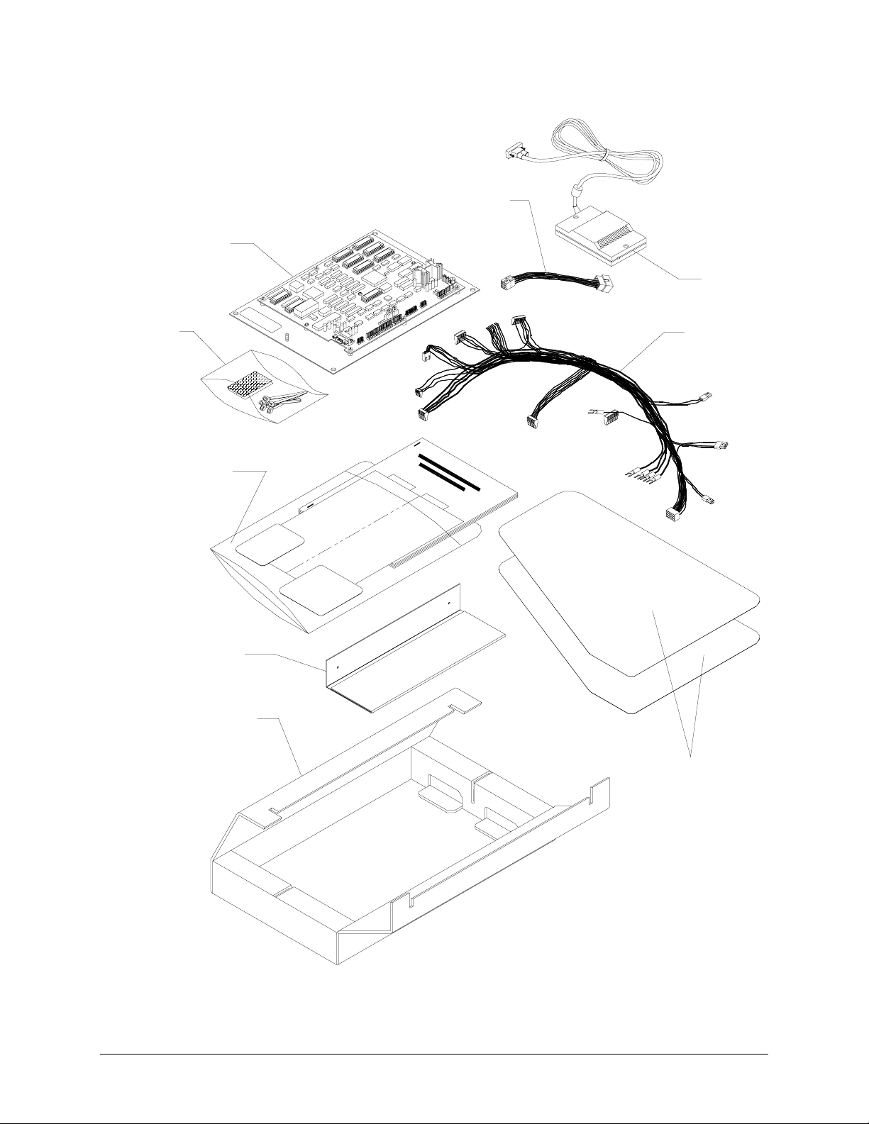
TOUCHMASTER® CONVERSION KIT PACKAGING
ADAPTER
GAME ELECTRONICS
TOUCHSCREE
CONTROLLER
FASTENERS
ENVELOPE CONTANING:
MANUAL, SMALL DECALS,
AND MARQUEE DECAL
MARQUEE RETAINER
HARNESS
CARTON
SIDE DECALS
Touchmaster® Conversion Kit Setup - 5
Page 8
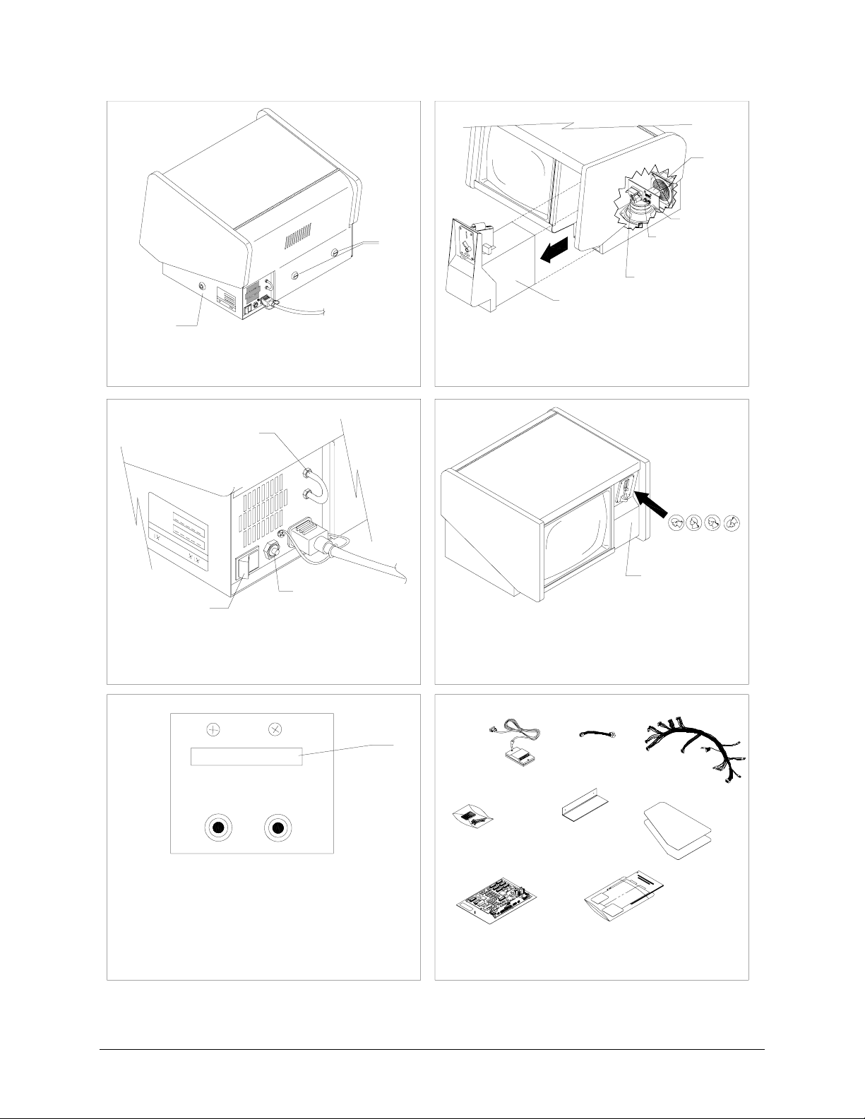
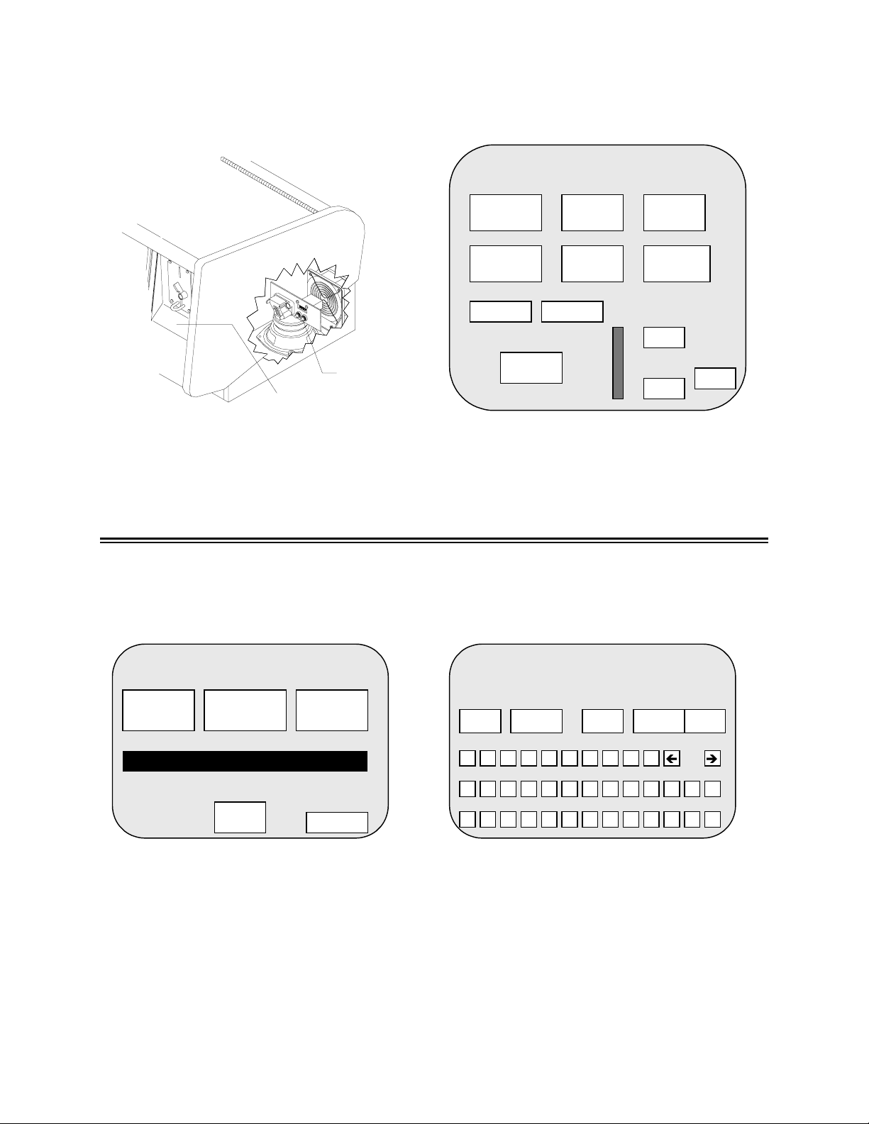
Verify operation of original VGM.
1
REAR
LOCKS
(some
models
CASH DOOR
LOCK
Vacuum loose dust from fan area. Unplug line
cord. Unlock cash door.
have only
one.)
2
COIN
METER
SETUP
BUTTON
CALIBRATE
BUTTON
CASH DOOR
CASH DOOR
CONNECTOR
Remove cash door to reveal coin meter, SETUP,
and CALIBRATE buttons. Note meter count.
Reinstall cash door.
3
CHAIN
LUG
CIRCUIT
POWER
BREAKER
SWITCH
Plug in line cord. Turn on AC power.
5
0 2 9 6 5 6
CALIBRATE SETUP
Note change
from before.
4
E
T
R
Y
R
B
Y
T
E
I
T
Y
B
L
R
I
E
L
B
I
L
9
9
9
9
1
9
9
1
1
99
9
CASH DOOR
Insert coins to play games. Verify operation and
record number of coins used. Remove cash
door to confirm meter has advanced once for
each coin.
CONTROLLER
6
FASTENERS
ADAPTER
MARQUEE
HARNESS
SIDE DECALS
9
9
9
1
Y
T
R
E
B
I
L
BOARD ASSEMBLY
AND DECALS
Press CALIBRATE button and follow
instructions on screen. Touch EXIT TEST on
screen. Press SETUP button, then the TEST
MANUAL
SCREEN button on screen. Line up crosshair
with cross. Then hit EXIT TEST on screen.
Turn off AC power and unplug line cord. Install
cash door. Unpack parts. Inspect for damage.
Setup - 6 Midway Amusement Games, LLC
Page 9

Remove original VGM electronics.
1
TOUCHSCREEN
CONNECTOR CABLE
TOUCHSCREEN
CONTROLLER
You may have one or
both of these connectors.
CABLE
Open cabinet door. Disconnect touch screen
connector and/or touch screen controller cable
connector, depending on model.
TYPICAL
POWER
SUPPLY
DC Volt.
2
COIN
FAN
SPEAKER
COIN LOCKOUT
Disconnect: 9- or 15-pin coin mechanism cable,
2-pin DC fan connector (some models do not
have one), 2-pin speaker connector, coin
lockout connector (if applicable).
43
FRONT
POSSIBLE
VIDEO
CONNECTOR
ORIENTATIONS
OR
UNIT
OF
Leave AC
SURGE
PROTECTOR
(not on all
models)
attached.
Detach all DC wires that lead to CPU Board
Assembly. Verify power supply connections.
5
CPU
BOARD
ASSEMBLY
Remove existing CPU Board Assembly with
original wiring attached.
and FG
wires
REAR
OF
UNIT
RED
WIRE
Locate video connector on monitor board. Record
orientation of red wire into this connector (toward
front or toward rear) and detach connector.
6
TOUCHSCREEN
CONNECTOR
CABLE
TOUCHSCREEN
CONTROLLER
Disconnect and remove touchscreen controller.
Remove any key plugs in connector cable
sockets. Leave cable in unit. Retain mounting
hardware (nuts or hook-and-loop fastener).
Touchmaster® Conversion Kit Setup - 7
Page 10
Install conversion VGM electronics.
1
UNKEYED BLACK
CONNECTOR
Snugly attach, but do not force wiring harness
connectors into new board assembly. On the
unkeyed black connector, tabs should face in
toward the board assembly.
HEAT SINK
MASTER VOLUME
CONTROL
2
HOOK & LOOP
BULKHEAD
CORD
TOUCHSCREEN
HOOK & LOOP
CONTROLLER
Attach touchscreen connector to controller.
Mount controller on bolts or with hook and loop
fastener so LED faces rear or right of VGM.
Attach any ground lugs to mounting bolt. Stow
excess cable between metal walls.
43
VIDEO
RED &
YELLOW
WIRE
ADAPTER
FAN
COIN
SPEAKER
COIN
LOCKOUT
TOUCHSCREEN
CONTROLLER CABLE
Orient board assembly with heat sink to front left
of VGM. Point volume control to front of VGM.
Slide CPU Board Assembly into cabinet. Attach
touchscreen controller cable to board.
5
(black)
(green/yellow)
TYPICAL POWER SUPPLY
H
+5V 12A
GND
(not used)
GND
-5V 1A
+12V 2A
FG
(red)
(green from touch controller)
(black or green)
(orange)
(orange from touch controller)
Attach DC power wires to power supply.
Attach touch controller wires to +12 and GND.
Stow wiring and cables in front of security bar.
Verify power supply connections.
Attach 6-pin connector to video board. Orient
yellow/red wire as red one was before. Attach:
fan, speaker, coin, and coin lockout (if applicable)
connectors. Use 9-pin adapter if needed.
6
MARQUEE RETAINER
MARQUEE
DECAL
LEFT SIDE
DECAL
FRONT PANEL
DECAL
Plug in VGM and turn on power. Calibrate and
test. Remove artwork. Align side decals with top
of cabinet. Apply decals trim to fit. Cut keyhole.
Apply correct sized front decal. Add marquee.
Setup - 8 Midway Amusement Games, LLC
Page 11
DETAILED INSTALLATION PROCEDURE
Verify Original Equipment Operation
INSPECT PARTS
1.
FLATTEN DECALS
2.
or magazines on them until the weight flattens them sufficiently for use.
CHECK CABINET
3.
VERIFY OPERATION
4.
startup. If the system starts without errors and enters the Attract mode it is considered functional.
5. Turn off power and unplug the VGM from the outlet.
CLEAN
6.
Vacuum the fan opening from outside the cabinet to remove loose dust.
7. Insert key into coin lock and turn clockwise to unlock. Pull the entire cash door out of VGM.
8. Locate the coin meter, CALIBRATE button, and SETUP button at rear of the coin vault.
Unpack the conversion kit and verify that nothing was damaged in shipping.
Unfold the side panel decals. Stack large, heavy items like newspapers, books,
Inspect VGM cabinet for damage. Repair before proceeding.
Plug in VGM and switch on AC power. A single beep should be audible during
FAN
COIN METER
SETUP BUTTON
CALIBRATE BUTTON
SPEAKER
CASH DOOR
CONNECTOR
CASH DOOR
9.
METER
CUTAWAY OF CASH VAULT WITH CASH DOOR REMOVED
Record the existing coin meter count and replace cash door tight with connections in rear.
10. Plug in line cord and turn on AC power.
CURRENCY
11.
Insert coins and play games to verify operation. Record number of coins used.
12. Remove the cash door and confirm that coin meter has advanced for each coin inserted.
ORIGINAL MANUFACTURER’S CALIBRATION
13.
Press the CALIBRATE button to perfor m original
manufacturer’s adjustment. If the touchscreen does not calibrate correctly, repair or replace it.
Touchmaster® Conversion Kit Setup - 9
Page 12
CALIBRATION SCREEN
TOUCH CENTER OF CIRCLE
CALIBRATION SCREEN
TOUCH CENTER OF CIRCLE
FIRST CALIBRATION SCREEN SECOND CALIBRATION SCREEN
14. The f irst c alibration dot appears in the upper r ight-hand corner of the screen. T ouch the center of this
circle with your finger. Finger position will be verified by an audible tone.
15. The sec ond calibration dot appears in the lower left-hand corner of the screen. Touch the center of
this circle with your finger. The VGM enters the Test Screen mode accompanied by an audible tone.
16. Touch the s creen and note that the crosshair centers beneath your fingertip. Touch all four corner s
and the entire bottom edge of the touchscreen. Touch the EXIT TEST button on the screen when
done.
17.
TRACKING TEST
18. A cross will appear in the center of the test screen. Touch the center of the cross and observe that the
crosshair centers on the cross. The crosshair will follow your finger as you move it across the screen.
Press the SETUP button. Touch the TEST SCREEN button on the screen.
EXIT
TRACKING TEST SCREEN
19. Touch the EXIT button on the screen.
If the crosshair was not centered on your finger, note the distance and direction it is off center. Return
to the calibration screen and place your finger on the screen slightly away from, but in the same
general direction and distance, from the dot to where the crosshair was off center.
Example: If the crosshair appears slightly below where you touched the screen, place your finger just
below the calibration dot. If the crosshair appears slightly above and to the right of where you touched
the screen, place your finger just above and to the right of the calibration dot.
Repeat the previous step for the second calibration dot. When the crosshair is centered on your finger
the screen is accurately calibrated. To accurately calibrate the screen, several attempts may be
required to compensate for the individuality of the touchscreen and its mounting on the CRT. Use the
CALIBRATE mode as needed to calibrate the screen as accurately as possible.
NOTICE
repair or replace any defective components before proceeding. The kit electronics will
not make these symptoms go away.
If the existing touchscreen cannot be calibrated correctly, troubleshoot and
Setup - 10 Midway Amusement Games, LLC
Page 13
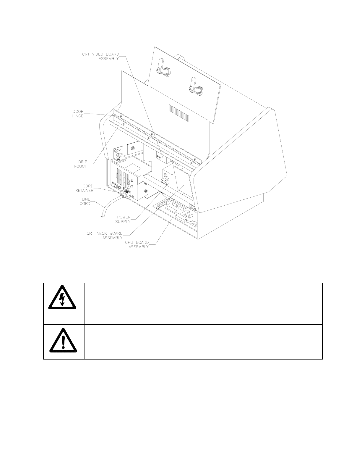
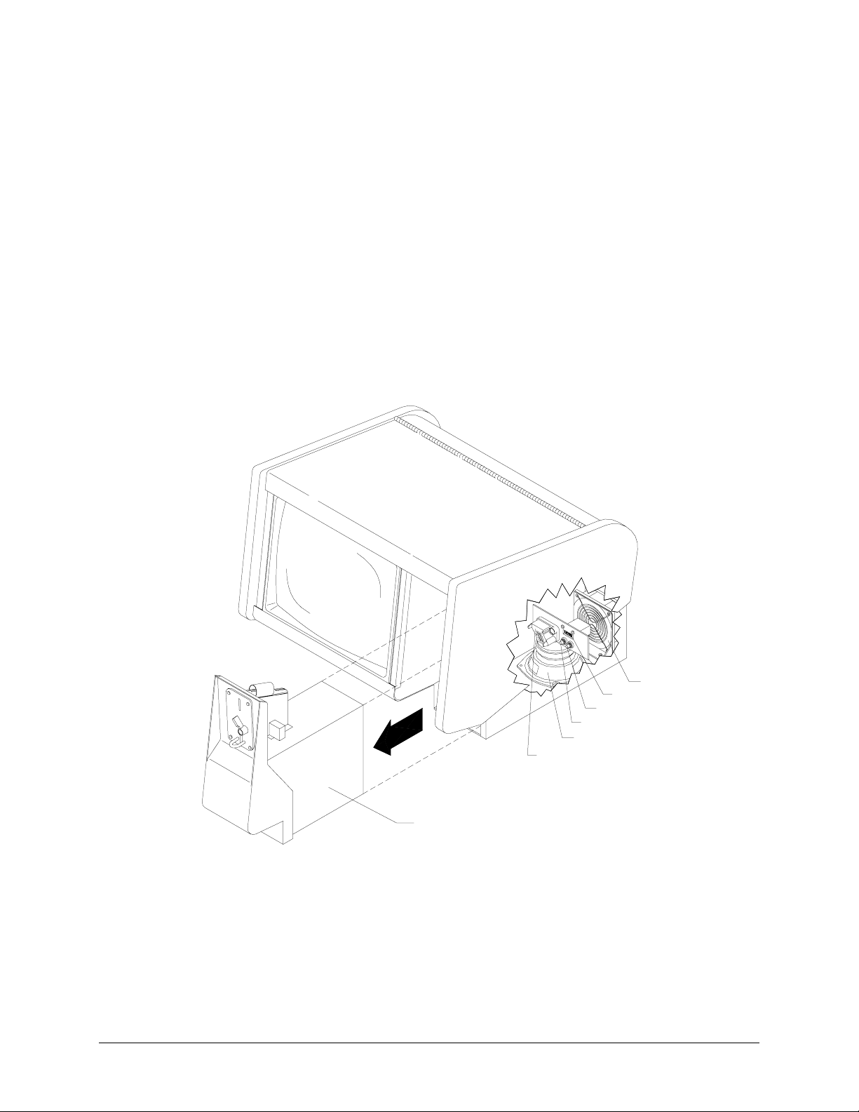
REMOVE ORIGINAL EQUIPMENT ELECTRONICS
REAR OF CABINET WITH DOOR OPEN
1. Unplug VGM. Insert key or keys into rear lock or locks and turn clockwise to unlock. Open cabinet
door.
DANGER: HIGH VOLTAGE
periods of time af ter power has been turned off. This is espec ially true when a defective
circuit prevents a normal discharge. Connect a very well insulated ground strap to the
metal chassis. Slide the f ree end of the strap under the CRT anode cap until c ontact is
made. Wait two minutes for charge recovery, then discharge the anode a second time.
DANGER: RADIATION
generate X-rays under fault conditions. Do not substitute high voltage components or
modify the circuit without fa ctory authorization. Follow the manufacturer’s directions for
measuring and adjusting the CRT anode voltage.
2.
GROUND WIRE
3. Locate each of the original equipment manufacturer’s cable and wire connections prior to
disconnecting them from the VGM electronics.
4.
TOUCHSCREEN
CPU Board Assembly at J5, disconnect it from the CPU Board Assembly. If a separate touchscreen
controller connector cable is also present, disconnect it (a D-subminiature connector) from the CPU
Board Assembly. You may have either or both connectors.
Remove ground wire, if present.
If the touchscreen connector cable (a rectangular connector) is connected to the
CRTs and their power supplies can retain energy for long
The high voltages used in the video monitor assembly can
5.
CONTROLLER
cable from the controller, if present. Leave the cable inside the cabinet and retain mounting hardware.
Touchmaster® Conversion Kit Setup - 11
Remove the touchscreen controller from the VGM. Detach touchscreen connector
Page 14
POLARIZING
KEY
TOUCHSCREEN
CONNECTOR
CABLE
REMOVAL OF POLARIZING KEY
KEY REMOVAL
6.
any keys with a sharp tool.
CONTROL
7.
FAN
8.
SPEAKER
9.
COIN LOCKOUT
10.
VIDEO
11.
Disconnect the 2-pin fan connector. Some models use an AC fan; no disconnection is needed.
Locate the video connector where it attaches to the monitor board. Record the orientation of
the red wire, either toward the front or toward the rear of the cabinet. Detach the connector.
POWER
12.
Loosen, but do not remove, the top six screws on the power supply terminal strip by turning
one full turn with a screwdriver. Do not loosen the bottom two (AC) screws.
Inspect the sockets of the touchscreen connector cable for polarizing key. Remove
Disconnect the 15-pin (or 9-pin, depending on your model) coin and control connector.
Disconnect the 2-pin speaker connector.
If your VGM has a coin lockout connector, disconnect it.
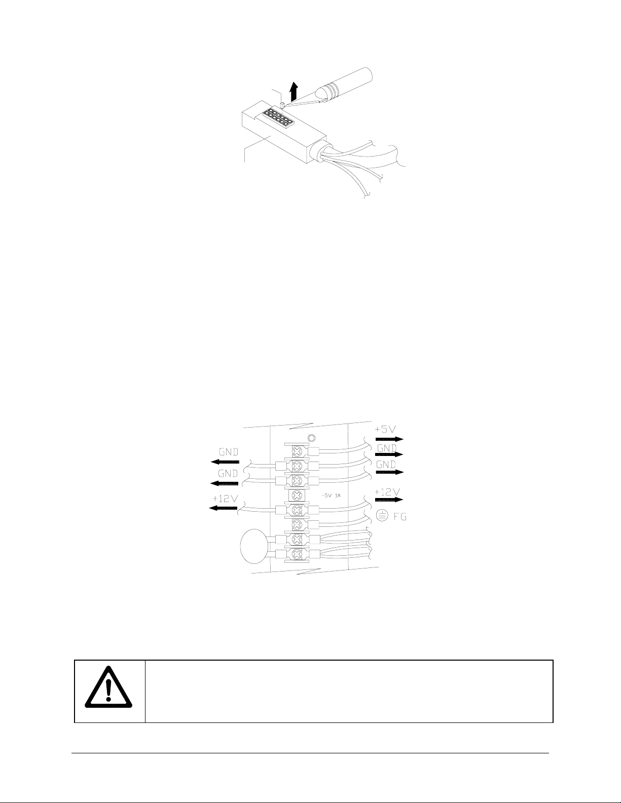
13. Remove the DC wires from +5, GND, -5, and +12 terminals. Leave the AC wires connected. If you
must disconnect a green and yellow striped AC connector to reach another connector, replace it.
REMOVAL OF DC WIRES FROM TYPICAL POWER SUPPLY
14. This is a typical view of the power supply connections. Verify the connections on your power supply.
CPU BOARD ASSEMBLY
15.
Slide the CPU board Assembly out of the cabinet with original wiring
attached. Make sure not to snag any hanging cables or wires. Store the CPU Board Assembly in an
anti-static bag.
WARNING: DO NOT SUBSTITUTE PARTS
Using inferior parts or modif ying a VGM
could cause serious injury or equipment damage! Use only Midway authorized parts.
For safety and reliability, do not substitute parts or modif y Midway products. Substitute
parts or modifications may void EMC directive or FCC type acceptance.
Setup - 12 Midway Amusement Games, LLC
Page 15
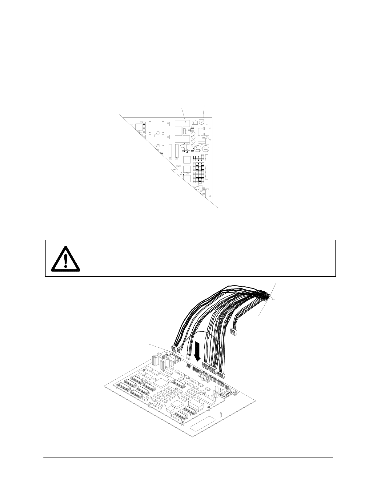
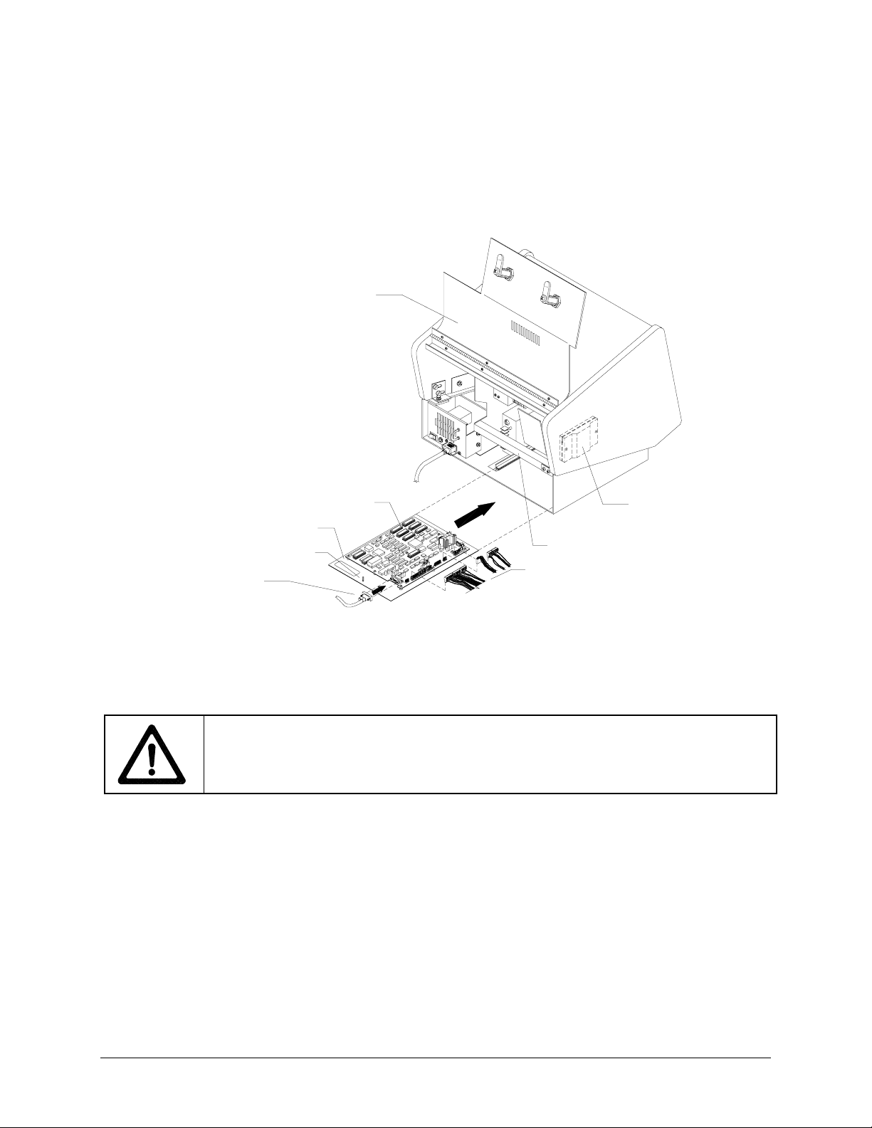
INSTALL GAME ELECTRONICS
1.
ORIENT ELECTRONICS
heat sink is near the video monitor. The heat sink should be toward the front left side of the cabinet,
opposite cash door.
2.
ADJUST VOLUME
the heat sink. Use a screwdriver to point the arrow toward the front of the cabinet.
Place the Touchmaster® CPU Board Assembly behind the cabinet so the
Set the master volume control to its middle position. The potentiometer is near
HEAT SINK
VOLUME
CONTROL
COMPONENTS ON CPU BOARD ASSEMBLY
3.
INSTALL WIRING HARNESS
Attach the keyed connectors to the CPU Board Assembly.
CAUTION: UNKEYED CONNECTOR
and can accidentally be reversed on the CPU Board Assembly. Make sure that when you
attach the connector, its tabs face inward toward the center of the board.
The black connector on the harness is unk eyed
BLACK
CONNECTOR
HARNESS INSTALLATION
Touchmaster® Conversion Kit Setup - 13
Page 16
TOUCHSCREEN
4.
MOUNTING
5.
Connect the touchscreen controller connector to the bottom of the new controller.
Orient the new controller in the same position as the previous controller so that the LED
faces the rear of the cabinet. If the controller is mounted on the rear bracket, the LED should face to
the right of the cabinet. If no controller existed before, install the hook and loop fastener material
included with the kit. Be certain that the controller position will not interfere with other components or
the closed cabinet door.
GROUND WIRE
6.
If there was an existing ground wire, attach it to the threaded stud on the metal
plate. A nut is supplied with the kit hardware just for this purpose.
REAR DOOR
PC BOARD ASSEMBLY
METAL PLATE
THREADED STUD
TOUCHSCREEN
CONTROLLER CABLE
SECURITY BAR
WIRING HARNESS
TOUCHSCREEN
CONTROLLER
TYPICAL REAR CABINET VIEW
INSERT VGM ELECTRONICS
7.
The CPU board assembly is mounted on a metal plate. Slide the
plate into the slots at the base of the VGM until it is clear of the cabinet door.
CAUTION: ROUTE CABLES IN FRONT OF THE CABINET SECURITY BAR
need to lock the cabinet door with the security bar later. Ensure you have clearance by
keeping all cables beneath and in front of the security bar.
FAN
8.
SPEAKER
9.
COIN
10.
pin connector, use the 9-to-15 pin connector to mate it with the 15-pin connector. Reconnect the coin
lockout connector, if applicable.
Attach the 2-pin fan connector if you disconnected it previously.
Attach the 2-pin speaker connector.
Attach the 15-pin coin mechanism cable connector. If your VGM’s coin mechanism has a 9-
. You will
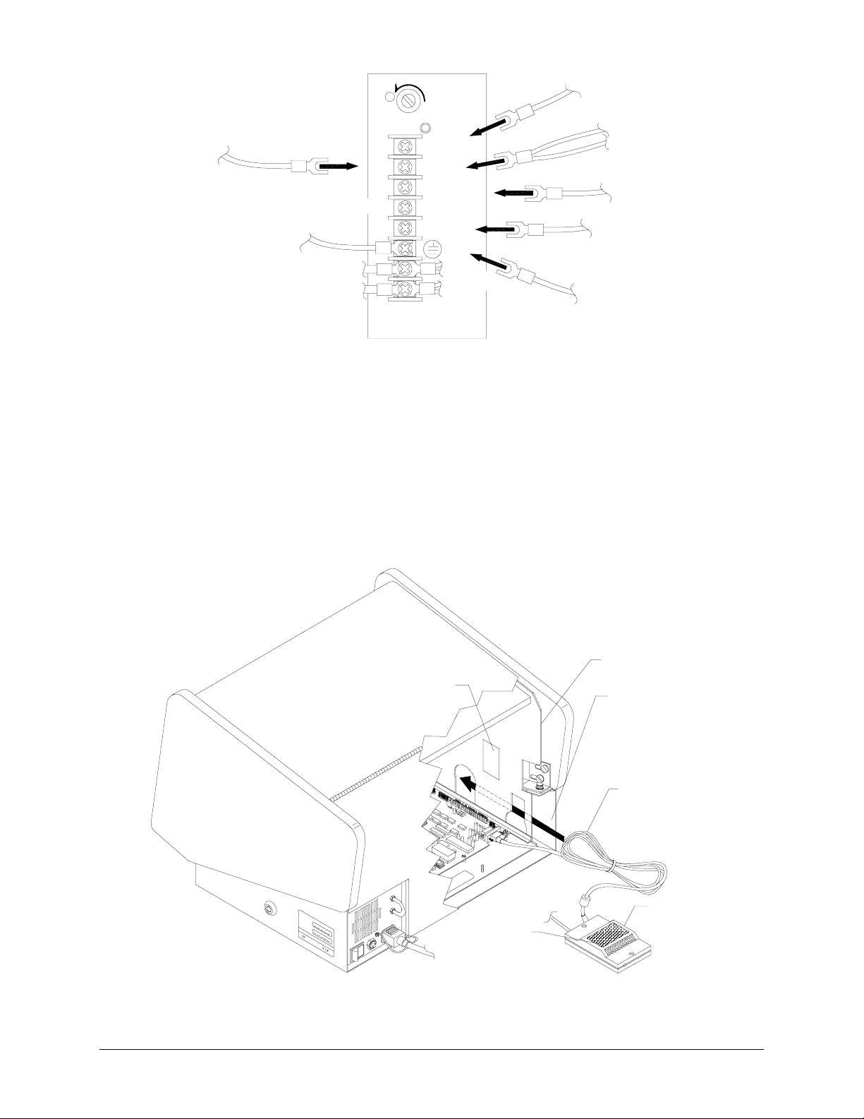
POWER
11.
Install the harness to the power supply terminal strip at the following screws:
+5V (red wire)
GND (black wire)
GND (black wire and green wire with yellow stripe)
+12V (orange wire)
FG (green wire with yellow stripe) should already be connected.
The –5V terminal is not used. The AC wires remain connected from the original equipment.
12. Attach touchscreen controller power wires at the GND screw (green) and the +12V screw (orange)
Setup - 14 Midway Amusement Games, LLC
Page 17
H
(red)
(black)
+5V
GND
(green from touch controller)
(black/green)
GND
(not used)
(green/yellow)
-5V 1A
+12V
(orange)
FG
(orange from touch controller)
AC 115V
95V~135VAC
190V~260VAC
INSIDE CHANGE
47Hz~63Hz
TYPICAL POWER SUPPLY CONNECTIONS
ATTACH
13.
CONTROLLER
14.
Secure, but do not overtighten, the top six screws on the power supply terminal strip.
Attach Touchscreen Controller Connector to the socket on the CPU Board
Assembly. Do not overtighten connector screws.
VIDEO
15.
Attach video connector to monitor board. Orient yellow and red-striped wire in connector
where existing red wire was previously oriented, as noted in electronics removal section of manual.
GROUND WIRE
16.
HARNESS ROUTING
17.
Reconnect any additional ground wires removed during disassembly.
Stow wiring in front of the security bar. Ensure that wires are clear of fan. Tie
wrap extra Touchscreen Controller Cable and store in between the cabinet bulkhead and outside
metal wall on the left. Failure to do so may cause difficulty calibrating touchscreen.
BULKHEAD
HOOK & LOOP
HOOK & LOOP
OUTSIDE
METAL
WALL
TOUCHSCREEN
CONTROLLER CORD
TOUCHSCREEN
CONTROLLER
TYPICAL TOUCHSCREEN MOUNTING AND CABLE STOWAGE
Touchmaster® Conversion Kit Setup - 15
Page 18
VERIFY NEW EQUIPMENT OPERATION
1.
START UP
After the Touchmaster
2.
ADJUST MONITOR
3.
CALIBRATE
Plug in the VGM and turn on power. The CPU Board Assembly LEDs should illuminate.
®
logo and game version appear on screen, close the cabinet door.
Correct size and position of on-screen video if needed.
Perform a touchscreen calibration. This sets the new values into the game memory.
RETURN
CONTROLLER VERSION
The screen
registers it
here.
Your
finger is
here.
INCORRECT TOUCHSCREEN ORIENTATION
4. In the calibration test, a vertical and horizontal line should cross beneath your finger. If the
touchscreen is inverted (that is, touching the screen in the lower left corner causes a reaction in the
upper right corner) your original equipment was inverted. You can correct this by following the
procedure on the next page. If you do not have an inversion problem, skip to the last page of this
chapter.
Setup - 16 Midway Amusement Games, LLC
Page 19

INVERTING TOUCHSCREEN SIGNALS
B
W
1. Turn off AC power and unplug the line cord.
2. Open the cabinet door.
3. Locate the P2 connector on
the CPU Board Assembly (at
the J6 designation) and
remove the connector from
the socket.
4. Using your fingers, pry off
the plastic strain relief cap.
Set the cap aside in a safe
place.
P2 CONNECTOR
HEAT SINK
FRONT OF
CABINET
CONNECTOR P2 ON CPU BOARD ASSEMBLY
REMOVAL OF CONNECTOR CAP
5. Remove the first wire (it will
be blue with a white stripe).
Replace the cap and close it
LUE AND
HITE WI RE
tightly.
REMOVAL OF BLUE AND WHITE WIRE
6. Insulate the blue, white-striped wire and secure it to the harness.
7. Reattach connector P2 to the CPU Board Assembly at J6.
8. Replace the electronics into the cabinet.
9. Close the cabinet door. Plug in the line cord. Turn ON the AC power.
10. Recalibrate the VGM.
FIRST WIRE
Touchmaster® Conversion Kit Setup - 17
Page 20
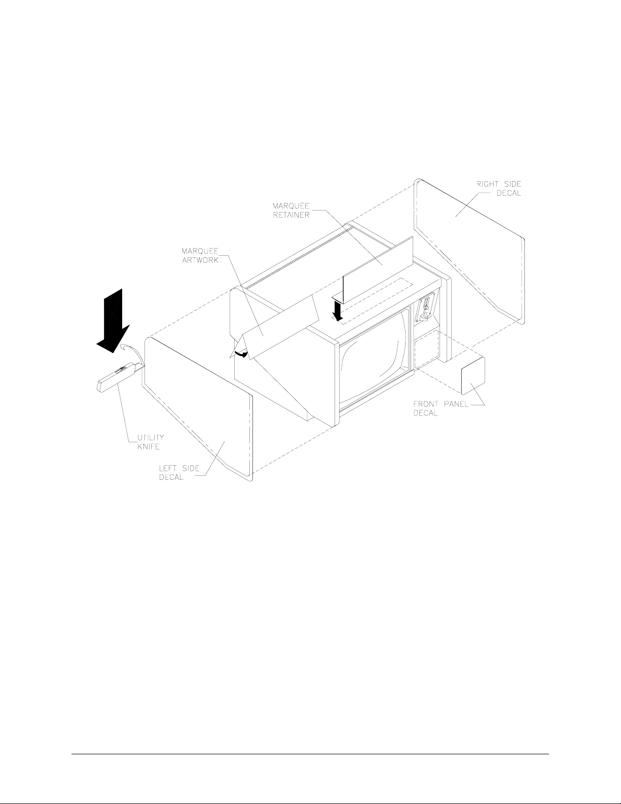
DECALS
1. Remove existing decals or artwork. Clean off all glue residue. Turn off AC power and unplug line cord.
2. Locate side panel cabinet artwork. The decals should be larger than the panels. One at a time, peel
off the backing and line up the artwork with the top of the left and the right panels of the cabinet. Use
care to avoid wrinkles. Moving outward from the center of the artwork, smooth down and squeeze out
any air bubbles. Cut decals with a utility knife to fit the panels exactly. Decal can wrap slightly over
edge onto trim area, if necessary.
LOCATION OF DECALS
3.
KEYHOLE
4. Select the front panel decal whose size is appropriate to your cabinet model. Center this piece on front
of cash door beneath currency acceptor and apply as in previous step.
5.
LABEL
underneath the monitor bezel.
6.
CURRENCY
7. Remove the cash door and confirm that coin meter has advanced for each coin inserted.
8.
OPTIMIZE
9.
MARQUEE
retainer on top of the cabinet. The magnets at the base of the marquee hold it in place.
Setup - 18 Midway Amusement Games, LLC
If necessary cut a circle in the right side decal to accommodate key insertion.
Locate the epilepsy warning label. Peel off backing and apply to the base of the cabinet just
Insert coins and play games to verify operation. Record number of coins used.
Read the operating instructions and make adjustments to optimize the games.
Fold marquee artwork in half and insert it into the marquee retainer. Place the plastic
Page 21
T
OUCHMASTER
®
CONVERSION
1
CHAPTER
2 3
2
54
YSTEM
S
NOTICE:
Amusement Games, LLC reserves the right to make improvements in equipment
function, design, or c omponents as progress in engineering or manuf acturing methods
may warrant. Field installed upgrade kits may also change the operating sequence or
functions.
NOTICE:
concerning this game.
Information in this manual is subject to change without notice. Midway
You are responsible for enforcing all local, state, and federal regulations
Page 22

GAME FEATURES
Touchmaster® has many different gam es. Each game c an accomm odate one or two players. Update the
software frequently to offer players new games, as well as interesting updates to existing games.
You can adjust the charac teristics of each game to suit the prof iciency of the players. Graphics may be
changed to alter the game appearance; the speed of the games may be increased or decreased, etc. This
flexibility increases the entertainment value of these games for frequent players.
Some versions include different games. International games permit play in several widely spoken
languages. Contact your authorized distributor to learn which games are available for your location.
Games are class ified according to the type of player challenge. Here are some representative examples
of games found in most Touchmaster
®
models.
DEXTERITY - Games that test the player’s eye-hand coordination
™
Hot Hoops
Touch the player to make him shoot at a moving basket. Surprise objects block shots at random.
PRESTIDIGITATION - Video versions of popular sleight-of hand tricks
™
Shell Shock
Pick the correct item that covers the pea. The shuffle speeds up as your skills improve.
TRADITIONAL - Electronic versions of old favorites
™
Solitaire
Use all the cards in the deck to build up the four suit stacks from ace to king.
MATHEMATICS - Test your ability to add different combinations of numbers
™
Triple Elevens
Assemble three groups of numbers whose total is eleven. How fast can you calculate sums?
LANGUAGE - Display word recognition skills
™
Wordz
Guess the phrase by picking letters to complete each word. Spelling counts, just like in school.
System - 2 Midway Amusement Games, LLC
Page 23

VIDEO GAME MACHINE (VGM) OPERATION
STARTING UP
Each time the game is first turned on or power is restored, it executes code from the boot ROM. These
self-diagnostic tests automatically verify and report the condition of the hardware and game EPROMs. If
any individual test fails an error message for that test is displayed for three seconds or until any on-screen
button is touched. If a fatal error (i.e., a touchscreen controller fault) is detected, the message remains on
the screen until the fault is resolved. In the event of other errors (key problems, low battery, etc.) a
message is reported, but the program loads and permits game play.
Press the CALIBRATE button at any time to adjust or verify the touchscreen operation.
Press the SETUP button at any time to activate the menu system (audits, adjustments, etc.).
If you do not press either button, the system completes all tests, then load and run the game.
Once all power-up tests are complete, the game goes into Attract mode. Game choice menus alternate
with scenes and sounds from typical games repeatedly until game play starts.
Insert currency to start the game. Select a game and choose game variables. Play begins immediately.
The game progresses until time runs out or you exit from the selected game. If no more play is required,
the game automatically returns to the Attract mode.
You may insert your own message to inform players of new games, upcoming events, etc. This message
then appears as one of the features displayed in the Attract mode.
To shut the game off, turn the power switch to the OFF position at any time.
PLAYER CONTROLS
This game uses an on-screen touch sensor on the CRT face to control all player moves and choices.
Players touch the screen for a moment in an active area to enter information. Touching inactive areas of
the screen produces no response. The touch sensor responds to only one active input at a time.
Touchmaster® Conversion Kit System - 3
Page 24

CONTROLLER
TOUCHSCREEN
TYPICAL LOCATION OF TOUCHSCREEN COMPONENTS
System - 4 Midway Amusement Games, LLC
Page 25

OPERATOR CONTROLS
CABINET SWITCHES
The external switches are located on the rear of the game near the line cord.
♦
Power Switch
The
Power Switch
♦
Circuit Breaker
The
Circuit Breaker
POWER
SWITCH
turns the game on or off. It does not reset the game variables.
protects the game from fault conditions. It does not reset the game variables.
CIRCUIT
BREAKER
TYPICAL CABINET SWITCH LOCATIONS
CONTROL SWITCHES
The internal switches are located behind the cash door. They are attached to a mounting bracket.
♦
SETUP BUTTON
The
SETUP
button takes you into the menu system to set gam e characteristics. An on-screen EXIT
button lets you to leave the menu system and return to Attract mode.
♦
CALIBRATE button
The
CALIBRATE
button takes you to a Touchs creen adj ustm ent sc reen and verif ication routine. Af ter
verification, normal game operation returns automatically.
♦
Master Volume Control
The
Master Volume Control
(on the CPU Board Assembly) sets the m aximum sound level for the
game. Adjust the game volume at the initial System Setup screen after pressing the SETUP button.
♦
Monitor Remote Adjustments
The
Monitor Remote Adjustment Board
(inside cabinet in the rear)
sets the video display for optimum viewing.
COIN METER
SETUP BUTTON
CALIBRATE B UTTON
TYPICAL CONTROL SWITCH LOCATIONS
Touchmaster® Conversion Kit System - 5
Page 26

MENU SYSTEM
SYSTEM OVERVIEW
Game variables and diagnostics are presented in a series of on-screen menus. The SYSTEM SETUP
menu allows you to enter information, make changes, or verify equipment operation. Each sub menu
screen displays one specific group of choices. The detail menu presents data or runs the required test.
You must be at the detail menu level to detect errors, make changes, or activate tests. Both the operator
controls and the player controls are used to move through the menus and start or stop particular routines.
Each menu is different, but the general location of objects is consistent.
The area at the top center of each screen displays the current menu title.
The center of the screen is used for data (menu items, video signals, statistics, reports, etc.).
The bottom of the screen is reserved for control functions (increase, decrease, next, return, etc.).
ORGANIZATION
You must activate the menu system manually and deactivate it manually to return to Attract mode.
SYSTEM SETUP menu choices fall into three categories: audits, options and tests.
Audits provide you with information about earnings and the performance of each game.
Option items permit you to change the game and customize or return to factory defaults.
Tests are used to verify proper operation of the equipment.
Sub menu screen items offer you choices within a category. Some items have no sub menu while others
may have several. You can return to the previous menu or go on to the next menu.
Detail menu screen items contain specific information. You interact with the system to get results or to
make changes. There is always a way to go back to the previous menus from a detail menu.
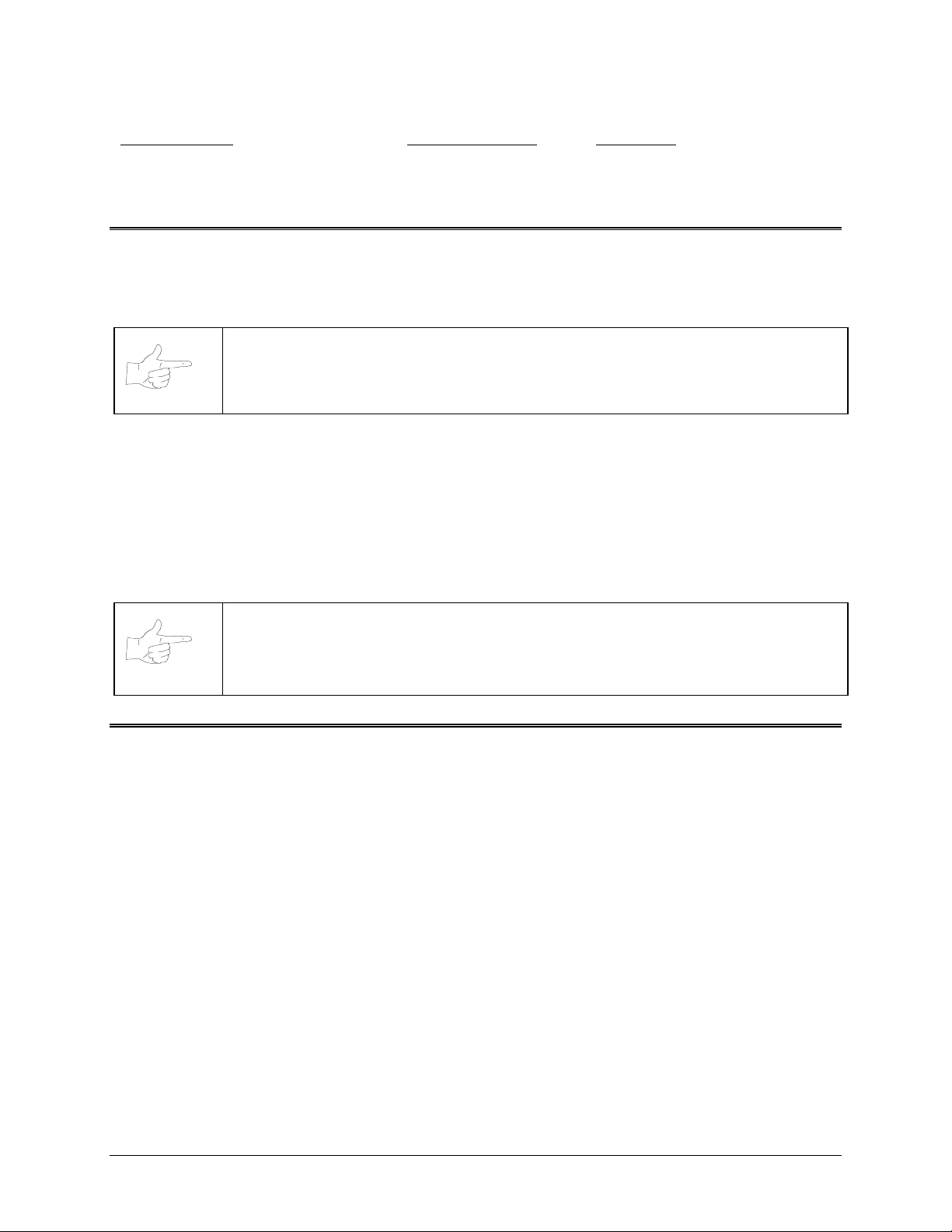
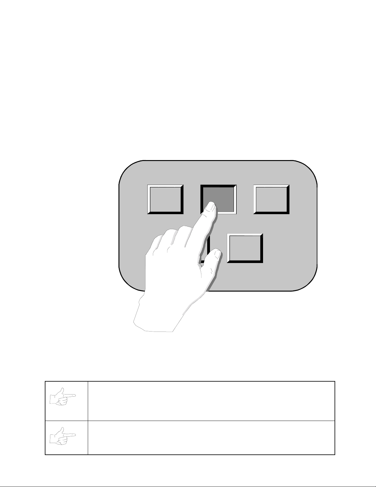
Touch the screen to select or highlight an item on any menu screen. Only one item can be highlighted at a
time. To restore the game to normal play, touch the RETURN box on each sub or detail menu and then
select the EXIT box at the Main Menu to restore game play.
Press and release the SETUP button inside the cabinet to enter the menu system. A Main menu, similar
to the one below, appears. After completing any task, you must return to this screen to restore game play
SYSTEM SETUP
VER : X.XX XXXXX XX/XX/XX
GAME-COIN
SETUP
OPERATOR
MESSAGE
ENGLISH ESPANOL
FREE
CREDIT
0
DISPLAY
AUDITS
LOCATION
SETUP
V
O
L
U
M
E
+
-
HIGH
SCORES
DIAGNOSTIC
EXIT
TYPICAL SYSTEM SETUP SCREEN
System - 6 Midway Amusement Games, LLC
Page 27

GAME/COINAGE SETUP
NOTICE:
Applicable law may dictate changes in the Touchm aster
®
game complim ent,
and may also regulate the appearanc e, bonus awards, language, or other variables on a
game-by-game basis. The ex ample here shows how operators might us e these utilities
to customize the Touchmaster
®
This menu allows you to change variables, such as game difficulty and appearance, and adjust the cost of
one play. You can also reset game variables to their factory default settings.
GAME/COINAGE SETUP
GAME SETUP
COINAGE
SETUP
RESTORE
FACTORY
SETTINGS
MAXIMUM
CREDITS
+
-
9
FREEPLAY
NO
RETURN
TYPICAL GAME/COINAGE SETUP SCREEN
MAXIMUM CREDITS
Touch the + button to increase the number of maximum credits. Touch the – button to reduce the number
of maximum credits.
FREEPLAY
Set FREEPLAY to YES to allow unlimited free games. Set FREEPLAY to NO to return to coin-activated
games.
Touch RETURN to return to the SYSTEM SETUP menu.
Touchmaster® Conversion Kit System - 7
Page 28

GAME ADJ USTMENTS
®
These sub menus let you change variables for each of the Touchmaster
games. At the GAME/COINAGE
SETUP menu, touch the GAME SETUP button to view the GAME ADJUSTMENTS menu.
RESET
+
-
NEXT
Returns variables to factory default values. This resets
Raises the value of the selected variable until the maximum value is reached.
Lowers the value of the selected variable until the minimum value is reached.
Saves the current on-screen values and advances to additional Game Setup screens.
GAME ADJUSTMENTS
GAME CREDIT TIME GRAPHIC
HOT HOOPS 1 MED -SHELL SHOCK 1 MED -TARGET 21 1 MED CARD
ROYAL QUEST 1 MED CARD
SOLITAIRE 1 MED CARD
MOVIE TRIVIA 1 MED -WORDZ 1 MED -PAIRS 1 MED CARD
TRIPLE ELEVENS 1 MED CARD
PYRAMID 13 1 MED CARD
RESET
+ -
all
your custom game settings.
NEXT
TYPICAL GAME ADJUSTMENTS SCREEN
When you touch the NEXT button, you are taken through several screens with individual game
adjustments. The final sub menu in this permits you to make some more general adjustments, such as
whether to award free games, enable erotic games, etc.
GAME ADJUSTMENTS
ROYAL QUEST – WILD CARDS
ROYAL QUEST – DECK
ROYAL QUEST – HI-LO BONUS
WORD GAMES - MAX. CHANCES
ENABLE EROTIC GAMES
AWARD FREE GAMES
HIGHEST SCORE FREE GAME
SHOW TRIVIA ANSWER
AUTO RESET HIGH SCORES
RESET
AFTER PLAYS
200
TYPICAL FINAL GAME ADJUSTMENTS SCREEN
YES
EASY
YES
6
YES
YES
YES
YES
RETURN
System - 8 Midway Amusement Games, LLC
Page 29

COINAGE SETUP
T
A
Z
B
B
C
L
F
F
G
I
I
This submenu lets you set individual revenue characteristics.
CANCEL
NEXT
CUSTOM
ACCEPT
Reverts to the previous menu without saving your changes.
Advances to the next sub menu.
Takes you to a sub menu where you can modify coin values
Saves your changes to coin values
PRESET COINAGE VALUES
OKEN JAPAN
USTRALIA NEW
EALAND
ELGIUM SPAIN
RAZIL SWEDEN
ANADA
SWITZER
AND
INLAND UK
RANCE USA
ERMANY CUSTOM
NDIA
TALY
CANCEL
NEXT
TYPICAL GAME COINAGE SCREEN
To access your currency from the PRESET COINAGE VALUES screen, touch your country to highlight it,
then touch the NEXT button.
PRESET COINAGE USA
USA1 $.25 = 1CR, $1.00 = 4CR
USA2 $.25 = 1CR, $1.00 = 5CR
USA3 $.50 = 1CR, $1.00 = 2CR
USA4 $.50 = 1CR, $1.00 = 3CR
USA5 $.25=1CR, $1=4CR, $5=24CR
CANCEL
CUSTOM
NEXT
TYPICAL PRESET COINAGE SCREEN
Touchmaster® Conversion Kit System - 9
Page 30

RESTORE FACTORY SETTINGS
This button permits you to globally change all customized settings (game, coin, name, etc.) simultaneously
to the condition they were in when the VGM was manufactured..
Since accidentally performing this operation can require you to spend much time resetting variables, a
warning screen lets you cancel this operation. The screen reads:
RESET FACTORY SETTINGS
WARNING
THE FOLLOWING WILL OCCUR
RESET GAME ADJUSTMENTS
CLEAR ALL AUDITS
CLEAR ALL HIGH SCORES
RESET OPERATOR MESSAGE
CONTINUE?
YES NO
TYPICAL RESTORE FACTORY SETTINGS SCREEN
If you touch YES, all factory settings are restored. Touching NO will return to the GAME/COINAGE
SETUP menu.
System - 10 Midway Amusement Games, LLC
Page 31

DISPLAY AUDITS
This submenu allows you to assess how well the games are played. The screen displays earnings and
other aspects of the game that reveal player skill levels. Statistics may be reset to zero after viewing.
CLEAR ALL
GAME DETAILS
Sets every audit quantity to zero. Record the information before using this command.
Takes you to a sub menu where you can view, clear, and reset high scores for
individual games. You can also reset high scores through the HIGH SCORES sub
menu. Details on the following page.
NEXT
Advances to additional GAME AUDIT screens. The screens repeat after the last is
viewed.
RETURN
Reverts to the main menu screen. The screen values remain without change.
GAME AUDITS
AUDIT TOTAL
1 PLAYER 39
2 PLAYER 0
TOTAL BUYINS 0
TOTAL GAMES PLAYED 39
FREE GAMES WON 0
FREE GAMES HI SCORE 9
FREE GAME BUYINS 2
AVG. GAME TI ME 1:35 MIN.
CLEAR
ALL
GAME
DETAILS
RETURN NEXT
TYPICAL GAME AUDIT SCREEN
Data in the Display Audits portion of the Menu System is presented in the following categories:
♦
Game Play: 1-Player games, 2-player games, Free game awards; Buyins; Average game times.
♦
Earnings: Coin and Credit statistics for each Currency Acceptor installed in the game.
♦
Game Comparison: Popularity and average length of game play for individual games.
♦
Game Specifics: Detailed account of characteristics applying only to one game.
Touchmaster® Conversion Kit System - 11
Page 32

HIGH SCORES
The HIGH SCORES submenu lets you view the top game scores and the player identifications. Players
who earn a high score may create an identifier of up to eight characters. The player can also skip this
opportunity and remain anonymous. In this case, the high score will be posted without any identifier.
NEXT
Saves the current on-screen values and advances to additional HIGH SCORE screens.
RESET ALL
RETURN
Saves the current on-screen values and reverts to the main menu screen.
Returns variables to factory default values. This erases
HIGH SCORE CLEAR/RESET
HOT
HOOPS
ROYAL
QUEST
WORDZ
PYRAMID
13
TIMES
SQUARE
NEXT
SHELL
SHOCK
SOLITAIRE
PAIRS
3 PEAK
STRIP
SEARCH
RESET
ALL
TARGET
MOVIE
TRIVIA
TRIPLE
ELEVENS
5 STAR
UPLIFT
RETURN
all
high scores and identifiers.
21
TYPICAL HIGH SCORE CLEAR/RESET SCREEN
Scores are ranked in numerical order, with the highest of the top ten scores listed first. When a high score
is bettered, the lowest score on the list is dropped to make room for the new one. Each game has a high
score screen, which you access by touching the button with the game’s name.
HIGH SCORES
SPECIFIC GAME
Name SCORE
1 – PR1 100000
2 – PR2 76000
3 – PR3 24000
4 - 0
5 - 0
6 - 0
7 - 0
8 - 0
9 - 0
10- 0
CLEAR RESET RETURN
TYPICAL GAME HIGH SCORE SCREEN
In the screen above, CLEAR erases all the scores, RESET restores the factory values of the top ten
scores, and RETURN brings you back to the HIGH SCORE CLEAR/RESET menu.
System - 12 Midway Amusement Games, LLC
Page 33

OPERATOR MESSAGE
1
2
3
4
5
6
7
8
Ð
The game can display an on-screen message to draw attention, announce contests, welcome players, etc.
CLEAR
BKGD
TEXT
VIEW
DONE
SHIFT
SPACE
ARROWS
Deletes all characters from the screen simultaneously. Use it to erase old messages.
Changes the color of the background area behind the message. Provides contrast.
Changes the color of the message. Each message line can be another color if you like.
Displays how your finished message will appear before it is saved in game memory.
Saves the message and background, then reverts to the main menu screen.
Changes the letter entry boxes to standard symbols. Use for math, punctuation, etc.
Enters a space between characters. Used to separate words and sentences.
These boxes control the up, down, left and right position of the cursor on the screen.
:
:
:
:
:
:
:
:
Í
Ï
Î
BKGD
CLEAR
0 1 2 3 4 5 6 7 8 9
A B C D E F G H I J K L M
N O P Q R S T U V W X Y Z
TEXT
VIEW
DONE
SHIFT
SPACE
TYPICAL GAME MESSAGE SCREEN
You can write a message of up to eight lines with 32 characters each. All the characters in each line can
be a different color than the other lines. You may also vary the color of the background area behind the
message. The Touchmaster
®
automatically centers each line of the message when it is displayed.
1. To create a new message, first reach the OPERATOR MESSAGE menu from the SYSTEM SETUP
menu.
2. Touch the CLEAR button to erase any existing message.
3. Select a background by touching the BKGD button until the texture you like is visible at the top of the
screen. At any time, you can touch VIEW to preview how your final message will look in Attract mode.
4. Select the color of the first line by touching the TEXT button until the line shows your preferred color.
5. Touch the sequence of letters and numbers to spell out the first line of your message.
6. Touch the SHIFT button to access punctuation and other symbols.
Ð
7. Touch
8. Use
button to begin entering the next line. Repeat for each line.
Ï, Í
, and Îto place the cursor where you need to correct errors.
9. Use the SPACE button to insert empty space between characters.
10. When you are satisfied with your message, touch the DONE button to save your message and return
to the previous screen.
Touchmaster® Conversion Kit System - 13
Page 34

LOCATION SETUP
®
This submenu contains three more submenus that permit you to customize your Touchmaster
:
LOCATION NAME, TOUCH KEY SETUP, and SERIAL NO. SETUP. You can also adjust the speed by
which your customized location name scrolls in Attract mode.
LOCATION NAME
To modify the location name displayed during Attract mode, enter the SYSTEM SETUP screen either by
pressing the SETUP button in the coin vault or using your touch key PIN to access the LOCAL
ADJUSTMENTS screen (explained on next page). You can enter up to 24 characters.
If you used the SETUP button, touch the LOCATION SETUP button on screen.
Press the LOCATION NAME button. Several buttons on this screen control text entry:
CLEAR
RETURN
SPACE
DELETE
SHIFT
ARROWS
Deletes all characters in the location name at once. Use this to erase old information.
Returns you to the Location Setup screen and saves your location and ID number.
Enters a space between characters. Use this to separate words and sentences.
Deletes the character above the flashing cursor and moves the remaining text to the left.
Changes the letter entry boxes to standard symbols. Use for math, punctuation, etc.
Move the flashing cursor left and right.
ENTER LOCATION NAME
_________________________
CLEAR SPACE DELETE SHIFT
0 1 2 3 4 5 6 7 8 9
A B C D E F G H I J K L M
N O P Q R S T U V W X Y Z
RETURN
Í
Î
TYPICAL GAME LOCATION SCREEN
The location and machine identification are convenience features and have no effect on game play. The
Touchmaster
®
automatically recalls this information if the game audit tables are printed out.
1. To enter your location name, access the ENTER LOCATION NAME screen.
2. Touch the CLEAR button to erase the existing location name.
3. Touch the character keys on screen to enter the numbers and letters that spell your location name.
4. Use the SHIFT key to access punctuation and other symbols.
5. Use the SPACE key to insert an empty space between characters.
6. The
Í
and
Î
buttons let you maneuver the flashing insertion cu rsor left and right in your location
name.
7. The DELETE key erases the character above the flashing insertion cursor.
8. When finished, touch the RETURN button to save the name and go back to the previous screen.
System - 14 Midway Amusement Games, LLC
Page 35

TOUCH KEY LOCATION ADJUSTMENT SYSTEM
The Touch Key
™
setup feature lets you make some “local adjustments” to games without removing the
cash door to access the SETUP button. A Personal Identification Number (PIN) gives access, allowing
you or other designated employees to vary loudness, insert new messages, reset scores, etc., without
having keys for the cabinet. The PIN can be altered regularly to prevent unauthorized changes to games.
TOUCH KEY PROGRAMMING
These steps explain how to activate the TOUCH KEY™ system.
Press the SETUP button inside the cabinet to enter the menu system. Touch the LOCATION SETUP
button on the screen. Touch the TOUCH KEY SETUP button to access the TOUCH KEY menu..
LOCATION SETUP
YOUR CUSTOMIZED NAME
LOCATION
NAME
UR CUSTOMIZED NAME ROLLS BY YOUR CUSTOMIZE
TOUCH KEY
SETUP
SPEED
MED
SERIAL NO.
SETUP
RETURN
In the TOUCH KEY menu, select a four-digit PIN by sequentially pressing any four keys. You can choose
any of the six keys more than once. Determine what adjustments to allow access to (high score, message
and name, volume, erotic access). Touch the ON button to activate your PIN. When finished, touch the
RETURN button. At the LOCATION SETUP menu, touch RETURN again to return to SYSTEM SETUP
TOUCH KEY™
KEYLESS ENTRY SETUP
1
ENTER 4 DIGIT PIN
2
6
5
3 4
ALLOW HIGH SCORE ACCESS . . . . .
ALLOW MESSAGE & NAME ACCESS
ALLOW VOLUME ACCESS . . . . . . . . .
EROTIC ACCESS
YES OFF ON RETURN
Touchmaster® Conversion Kit System - 15
YES
YES
YES
Page 36

TOUCH KEY USE:
You can turn over local adjustments to designated employees using this procedure:
1. While in Attract mode, touch the Midway Amusement Games, LLC logo at the bottom of the screen.
CATEGORIES
CARD ACTION WORD
SKILL NEW
UR CUSTOMIZED NAME ROLLS BY YOUR CUSTOMIZE
SPANISH ENGLISH
MIDWAY
AMUSEMENT
GAMES, LLC
2. Touch the four numbered keys to enter the PIN. Each key highlights as you touch it. The correct PIN
reveals the LOCAL ADJUSTMENTS menu. The wrong PIN begins a series of high score screens.
TOUCH KEY™
YOU’RE IN
1
COMMAND!
2
6
5
3 4
INSERT COINS
MAIN
MENU
3. In the LOCAL ADJUSTMENTS menu, you can change the custom message, clear or reset high
scores, change your custom location name, adjust the volume, change the language of the game’s
text, turn the erotic games on or off, or perform a touchscreen calibration.
4. When finished making local adjustments, touch the EXIT button to return to Attract mode.
5. Explain the policies governing when changes should be made (i.e., lowered volume levels or erotic
game access after a certain time of day, messages advertising tournaments, etc.). Describe situations
when game scores might be reset. Demonstrate location adjustments and explain each feature.
6. Have chosen individuals memorize the PIN. Explain how often it will change and whom to contact if it
fails to work. Show that the code functions only if the key system is enabled, but the game continues
to operate and play normally. Have them enter codes to verify their understanding of the system.
7. Demonstrate the touc hscreen operation. Describe incorr ect tracking and what happens if the scr een is
out of calibration. Show how to calibrate the touchscreen, and how to test the calibration tracking.
8. If you forget the PIN, you can reset it as long as you have access to the SETUP button.
System - 16 Midway Amusement Games, LLC
Page 37

SERIAL NO. SETUP
You can enter a four-digit alpha-numeric serial number. If you have multiple VGMs that can print reports,
serial numbers can identify each unit. SERIAL NO. SETUP cannot be accessed through Touch Key. The
only time you will see your serial number is when you return to this screen or create a printout.
CLEAR
RETURN
SPACE
DELETE
SHIFT
Deletes all characters in the location name at once. Use this to erase old information.
Returns you to the Location Setup screen and saves your location and ID number.
Enters a space between characters. Use this to separate words and sentences.
Deletes the character above the flashing cursor and moves the remaining text to the left.
Changes the letter entry boxes to standard symbols. Use for math, punctuation, etc.
ENTER MACHINE NUMBER :
CLEAR SPACE DELETE SHIFT
0 1 2 3 4 5 6 7 8 9
A B C D E F G H I J K L M
N O P Q R S T U V W X Y Z
RETURN
Í
TYPICAL SERIAL NO. SETUP SCREEN
Î
Enter a unique machine number for each unit at a location. Keep a master list of machines for future
reference.
1. To enter your serial number, access the SERIAL NO. SETUP SCREEN through the LOCATION
SETUP submenu.
2. Touch the CLEAR button to erase the existing serial number.
3. Touch the four characters or numerals to spell out your serial number.
4. Use the DELETE button to correct mistakes.
5. Use the SHIFT button to access punctuation and other symbols.
6. Use the SPACE button to insert empty space between characters.
7. Touch RETURN to save your number and return to the LOCATION SETUP screen.
Touchmaster® Conversion Kit System - 17
Page 38

DIAGNOSTIC
Use the Diagnostic routines to check display performance, to verify sounds and music, to test switches,
and to calibrate and verify the Touchscreen.
VIDEO TEST
SOUND TEST
SWITCH TEST
CALIBRATE
CALIB. TEST
RETURN
Choose this test group to examine the CRT linearity, uniformity, or color characteristics.
Check the audio components with game sounds and music. Have you heard them all?
Manually test of currency acceptors, cabinet SETUP and CALIBRATE switches.
Set the Touchscreen Controller coordinates to correspond to fixed screen locations.
Verify Touchscreen sensitivity and linearity for the entire active touchscreen area.
Revert to the main menu screen. You can then return to Attract mode.
DIAGNOSTIC
VIDEO TEST
SOUND
SWITCH TEST
TEST
CALIBRATE
CALIBRATE
TEST
RETURN
TYPICAL DIAGNOSTICS SUB MENU SCREEN
These routines provide you with a means of keeping the Touchmaster
®
in top operating condition. Perform
these tests on a regular basis. Players may lose interest if they have to compensate for screen
maladjustments, in addition to remembering the rules of the game. All of these tests are brief, and may be
done in any order.
When you make adjustments to the Touchmaster
®
calibration settings, the values are stored in memory.
The game is very stable and retains its accuracy if not moved from the spot where it was last calibrated.
However, the internal electronics cannot compensate for changes in nearby magnetic and electrical fields
that may occur when the game is relocated to another position.
Verify the calibration each time the Touchmaster
®
is moved, in addition to the regular maintenance
checks, for best game performance.
.**Some games do not have a SET CLOCK box. The clock provides accurate time and date information
which is required to set the length of tournaments and communicate network data. Once set, the clock
runs until the battery dies or some major fault occurs. Periodically examine the time and date on the
system setup screen for correct values, and use the SET CLOCK utility to make changes when needed.
You can run the Calibrate routine without going through the Menu System by pressing the CALIBRATE
button in the coin vault. However, this omits the Touchscreen Controller tracking test. The CALIBRATE
button was included to encourage a quick check of the touchscreen functions each time the cash door is
emptied.
System - 18 Midway Amusement Games, LLC
Page 39

VIDEO TEST
Video tests provide patterns which verify monitor performance or making adjustments. You can modify
some monitor characteristics using the monitor controls remote board.
ALIGNMENT GRID
GRADIENT TEST
COLOR BARS
RED SCREEN
GREEN SCREEN
BLUE SCREEN
Lets you check or adjust monitor convergence, linearity, and dynamic focus.
Permits you to optimize CRT screen image for brightness and contrast.
Lets you analyze red, green, blue, and white balance.
Solid red screen for purity tests. Red should be the only color showing.
Solid green screen for purity tests. Green should be the only color showing.
Solid blue screen for purity tests. Blue should be the only color showing.
ALIGNMENT
GRID
RED
SCREEN
GRADIENT
TEST
GREEN
SCREEN
COLOR
BARS
BLUE
SCREEN
RETURN
TYPICAL VIDEO TEST MENU SCREEN
®
It is vital that the information on the video display for the Touchmaster
is accurate, since the CRT screen
is also the control panel for this game. Use these test patterns often to ensure precise game images.
Game players tend to be more critical when they are close to the monitor, and the Touchscreen Controller
requires intimate screen contact. This is especially true of small screen versions, since some of the
sensor areas are the same size as the contact area of the player’s fingers.
The ALIGNMENT GRID fills the screen with a series of lines and dots. The lines and dots should be all
one color, with no fringes or parallel images. The lines must be straight and the dots very nearly round.
Two color bars should be visible at the center of each screen edge. These bars verify scan size.
The GRADIENT TEST covers the screen with shades of colors to verify red, green, blue, and white level
dynamic adjustments. Each color bar should appear sharp, clear, and distinct from the others. This test
indicates a need for adjustment if some of the bars appear to be missing or blend together at the edges.
The COLOR BARS screen displays each of the standard colors and shades produced by the game’s
video circuits. The vertical bars must be uniform from top to bottom. The horizontal bars should show
small changes in intensity or shade from side to side. A sudden transition in any bar indicates a fault.
RED, GREEN, and BLUE SCREENS fill the screen entirely with the chosen color at normal intensity. Each
screen should be absolutely uniform from top to bottom and side to side. No retrace lines or noise should
be visible. These tests verify that the black level, degaussing, and blanking circuits are correct.
Touchmaster® Conversion Kit System - 19
Page 40

SOUND TEST
R
+
Sound test allows you to ensure that audio components are connected and operating properly.
STOP
Ends the selected sound. You can halt repetitive sound tracks with this button.
PLAY
Starts the selected sound. You can start another sound while one is still playing.
BACK
Selects the previous sound choice. Each single touch decrements the counter by one.
NEXT
Selects the next sound choice. Each single touch increments the counter by one.
Raises the volume of the sound in steps until the maximum value is reached.
+
Lowers the volume of the sound in steps until the minimum value is reached.
-
RETURN
Reverts to the previous screen. Touching RETURN again takes you to the SYSTEM SETUP
menu. Touching EXIT at this point takes you back to Attract mode.
SOUND TEST
STOP PLAY
BACK NEXT
TYPICAL SOUND TEST MENU SCREEN
Each Game sound is stored in a discrete memory location. All sounds are available to test the audio
reproduction capabilities of the sound circuits. Vary the volume as you sample these sounds to determine
if loose wire connections, faulty memory, digital-to-analog conversion problems, a defective speaker, etc.
could be causing distorted or missing sound effects. Select a repetitive sound track and a high volume
level if you suspect errors caused by heat or time-related problems.
The sounds may be examined in any order. Touch the + or - buttons to change the volume as necessary.
Touch RETURN to end these tests and go back to DIAGNOSTICS, then RETURN and EXIT to go back to
Attract mode.
There are three types of sounds used in the Touchmaster
events such as a touch selection or an incorrect answer to a question. A dog barking, a cowbell, and the
“boing” are examples of these sounds. Medium-length phrases are used to announce the start or end of a
game, bonus rounds, or a new high score. These phrases can last from one to five seconds. The final
group of sounds are repetitive sounds like a jazz-drum riff or the ticking of a clock. These sounds are used
to distract the player and to attract others to the game.
SOUND
V
O
L
U
M
E
1
+
-
®
games. Short bursts of sound indicate single
ETURN
NOTICE:
game play. Be sure to set the volume back to a reasonable level when you have
concluded the tests.
NOTICE:
potentiometer only if there is not enough range in the on-screen volume adjustment.
Refer to audio Troubleshooting.
System - 20 Midway Amusement Games, LLC
The volume adj ustm ent in the s ound tests is the sam e as the one us ed for the
There is a mast er volume control on the CPU Board Assembly. Change this
Page 41

R
SWITCH TEST
Switch tests allow you to manually check each switch used in the game. Because the Touchsc reen uses a
digital controller to sense player input, it has a separate test (refer to Calibrate steps).
OPEN
CLOSED
RETURN
Indicates a circuit with no continuity. This is a Normally Open switch condition.
Indicates a circuit with continuity. This is a Normally Closed switch condition.
Reverts to the Sub Menu screen. Touch RETURN again to go to the Main Menu.
SWITCH TEST
J2 – 10 M. COIN 1 INPUT- -------- OPEN
J2 – 9 M.------------------------------ OPEN
J2 – 8 DBV INPUT ----------------- OPEN
J2 – 5 TEST ------------------------- OPEN
J2 – 4 CALIBRATE--------------CLOSED
J9 – 7 E. COIN 1 INPUT---------- OPEN
J9 – 8 E. COIN 2 INPUT---------- OPEN
J9 – 9 E. COIN 3 INPUT---------- OPEN
J9 – 10 E. COIN 4 INPUT---------- OPEN
0.0.0
ETURN
TYPICAL SWITCH TEST MENU SCREEN
®
The Touchmaster
Each line item on the screen represents an input signal from the currency acceptors or the push button
switches. The screen above is correct for a Touchmaster
game electronics expect all switches to be Normally Open except when activated.
®
with the Calibration button depressed and held.
The game detects and displays the status of each switch independently, permitting switches to be
checked for interaction or incorrect programming (electronic currency acceptors).
In addition to the on-screen OPEN or CLOSED indication, the Touchmaster
®
audio circuits generate a
clunk noise each time a switch is closed. Use this to locate shorted or intermittent connections when you
are working from the back or sides of the cabinet and cannot see the monitor screen.
Example: Suppose a different coin mechanism must be installed to accept another type of coin than was
previously used. Turn off the game power and open the Cash Door. Remove the existing mechanism and
replace it with the alternate unit. After the new mechanism has been mounted and connected to the game
electronics, the game must be matched to the new currency values. Power up the game and verify the
Touchscreen operation (minor calibration may be required after any type of product service).
Check switch operation for the game Currency Acceptors in the following manner: Press the SETUP
pushbutton to display the Menu System. Choose DIAGNOSTICS to get to the Sub Menu, then choose
SWITCH TEST to go to the switch menu screen (a typical game SWITCH screen is illustrated; your
Touchmaster
Press and hold the CAL. push button. The Touchmaster
®
may have a different compliment of Acceptors).
®
emits CLUNKing sounds and indicate this switch
is CLOSED on the screen. Release the button to stop the sound and revert to an OPEN state. Repeat
these steps for other switches in the game. When finished, choose RETURN and EXIT to quit.
NOTICE:
Continuous clunk noises can indicate wiring defects, jamm ed switch, bad IC,
etc.
Touchmaster® Conversion Kit System - 21
Page 42

CALIBRATE
This procedure lets you correct the accuracy of the Touchscreen controller.
Dot for controller calibration. This sets the ability to correctly recognize a player’s touch.
CALIBRATE TOUCHSCREEN
TOUCH WHITE DOT IN:
LOWER LEFT CORNER
CALIBRATE TOUCHSCREEN
TOUCH WHITE DOT IN:
UPPER RIGHT CORNER
TYPICAL CALIBRATION SCREENS
Box for controller verification. This verifies the Touchscreen accuracy in critical areas.
1 2
3 4
CALIBRATION TEST
PRESS EACH RED BOX
5 6 7 8
CYCLE POWER AND RECALIBRATE
IN CASE OF TROUBLE
9 10
11 12
TYPICAL CALIBRATION TEST SCREEN
The Touchscreen Controller in the Touchmaster
®
senses the position of your finger based on its
capacitance. The Touchscreen uses a very weak uniform electrical field. Touching the screen disturbs the
field. The controller tracks the disturbance and translates it into a location. The game electronics interpret
the location information into commands. The process occurs in a fraction of a second, allowing the game
to respond rapidly.
®
When the Touchmaster
is moved from one location to another, the amount of capacitance changes. This
causes the controller to shift its tracking coordinates and may generate errors in some screen areas. The
Calibration routine allows the controller to adjust its tracking to match the touch point.
Calibration screens require you to touch one specific location as indicated by a single dot. Touch the dot
and hold this position until coarse tracking adjustments are completed (about two seconds). The
Touchmaster
®
automatically advances to the next screen and emit a short burst of sound. Repeat this
procedure for each screen with a single dot. The Calibration Test screen (see next page) tracks finger
position over the entire screen, allowing the entire playing surface to be checked for accurate calibration.
Verification screens require you to touch several locations as indicated by several boxes. Touch each box
and hold this position until fine tracking adjustments are completed (about one second). The
Touchmaster
®
displays one vertical and one horizontal line on the screen. The lines should intersect over
the box when you remove your finger. Repeat this procedure for each box on the screen.
System - 22 Midway Amusement Games, LLC
Page 43

CALIBRATE TEST
This test verifies touch tracking for the entire active screen area and lets you detect any calibration errors.
Intersecting lines indicate screen location coordinates from the Touchscreen Controller.
+
RETURN
Returns you to the previous screen.
RETURN
CONTROLLER VERSION X.XX
TYPICAL CALIBRATION TEST SCREEN
Check the accuracy of the Touchscreen Controller can be checked without going through a new
calibration procedure. This test quickly detects any non-linear or unresponsive areas of the Touchscreen.
The Controller Version number indicates the model of controller used in this unit. Because of space
limitations, the Touchscreen Controller is mounted where these numbers may be difficult to view easily. If
customer assistance is required, the service person may request this number during problem solving.
The first time the Touchscreen Controller is calibrated, the tracking data is stored in a section of the
Touchmaster
changed if the game has been serviced or relocated. The test does not change the data stored in
memory. The only way to replace the existing data with new information is to go through each of the
calibration steps. Use Calibrate Test on a regular basis to determine if a new calibration is necessary.
1. Touch CALIBRATE TEST to view the test screen. The lines should intersect at the screen’s center.
2. Touch any location on the screen. The lines intersect at the point of contact.
3. For each additional touch point, the lines must intersect under your fingertip. Drag your finger across
the screen, as well as lift it from the screen and place it down again.
4. Check several locations, especially along the outer perimeter of the screen. If
visible beside your finger after the lines stop moving, recalibrate the touchscreen.
5. Touch RETURN to end the test and go back to the DIAGNOSTICS screen. If you encountered errors
in the test, choose CALIBRATE and complete each step.
6. When the CALIBRATE TEST results are satisfactory, select RETURN to go to the main menu and
EXIT to return to Attract mode.
®
memory. Each time the screen is touched this information is recalled. This data must be
either
or both lines are
NOTICE:
Always re-calibrate and test the VGM after moving your Touchmaster
®
.
Touchmaster® Conversion Kit System - 23
Page 44

NOTES
______________________________________________
_____________________________________________
_____________________________________________
_____________________________________________
_____________________________________________
_____________________________________________
_____________________________________________
_____________________________________________
_____________________________________________
_____________________________________________
_____________________________________________
_____________________________________________
_____________________________________________
_____________________________________________
_____________________________________________
_____________________________________________
_____________________________________________
_____________________________________________
_____________________________________________
System - 24 Midway Amusement Games, LLC
Page 45

®
T
OUCHMASTER
CONVERSION
CHAPTER
1
2 3543
Service
WARNING: DO NOT SUBSTITUTE PARTS.
LLC Parts or circuit modif ications may cause serious injury or equipment dam age! Use
only Midway authorized parts.
For safety and reliability, do not substitute parts or modif y Midway products. Substitute
parts or modifications may void EMC directive or FCC type acceptance.
Use of non-Midway Amusement Gam es
Page 46

A-23380-33 CPU BOARD ASSEMBLY
Field Replaceable Parts
Designation Part Number Function Description
J12 --- (see Note 1) Security Key Custom Assembly
U8 --- (see Note 1) Sound Program EPROM Assembly
U36 --- (see Note 1 & 2) Game Program EPROM Assembly
U37 --- (see Note 1 & 2) Game Program EPROM Assembly
U38 --- (see Note 1 & 2) Game Program EPROM Assembly
U39 --- (see Note 1 & 2) Game Program EPROM Assembly
U40 --- (see Note 1 & 2) Game Program EPROM Assembly
U41 --- (see Note 1 & 2) Game Program EPROM Assembly
U51 --- (see Note 1 & 2) CPU Instructions EPROM Assembly
U52 --- (see Note 1 & 2) CPU Instructions EPROM Assembly
U62 --- (see Note 1 & 3) Memory Backup Nonvolatile SRAM with Battery
NOTES
: 1. Version specific. Contact your distributor for the latest part numbers of these components.
2. Some versions of software do not require that all sockets be filled.
3. The battery is permanently attached to the memory IC and cannot be replaced separately.
Service - 2 Midway Amusement Games, LLC
Page 47

SERVICING
We recommend that you read the SAFETY NOTICES section thoroughly before beginning service.
This VGM uses complex electronic components that can be very SENSITIVE to static electricity.
The following precautions must be observed and followed prior to handling any of the electronics.
1. Ensure that the AC power to the VGM is turned OFF prior to servicing the electronics.
2. Discharge any static electricity build up in your body by touching the VGM cabinet metal base.
This must be done BEFORE touching or handling the electronic assemblies.
3. Store the electronic assemblies in an anti-st atic area. Anti-static bags are to be used to store
VGM electronic assemblies. Reuse the bag to store removed boards during service.
4. DO NOT remove or connect any electronic assemblies when the cabinet pow er is ON. Doing
so will damage the electronic assemblies and void the warranty.
5. Always replace ground wires, shields, safety covers, etc. when maintenance or service is
completed. Ensure that all ground and mounting screws are installed and tightened firmly.
Cabinet (Top Cover)
♦
Switch off power to the VG M and unplug f rom AC power. Insert k ey or keys into rear door lock s. Tur n
each key clockwise to unlock. Lif t the access door up from the cabinet. Reach inside the rear of the
cabinet to loosen and remove the thum bscrews and washers used to hold the cover in place. Store
screws and washers in a safe place. Slide the cover forward approx imately 1/2 inch (12 mm) until it
stops. Lift up both side panels and remove the cover from the base. Set the cover in a safe place.
OPENING THE CABINET FOR SERVICE
Touchmaster® Conversion Kit Service - 3
Page 48

Refer to the original equipment manufacturer’s manual for information relating to the removal and
installation of approved parts for the following components.
Power Supply Speaker Coin Meter Control Switches Rotating Base
Monitor Bezel
and Gasket
Monitor Cash Door
Fan Assembly Power Switch or
Assembly
Circuit Breaker
MONITOR BEZEL
AND GASKET
MONITOR
CASH DOOR
ASSEMBLY
CONTROL SWITCHES
(CALIBRATE & SETUP)
SPEAKER
FAN ASSEMBLY
COIN METER
LOCATION OF ORIGINAL COMPONENTS
Signage Kit (Optional)
♦
The original VGM sign was attached with screws to the top cover of the cabinet. If this sign is brok en or
missing and an exact replacement is not available, use the optional Touchmaster
®
signage kit.
Grasp the top edge of the sign holder and pull it forward and down to free the magnet strips from the
top cover, then lift the sign up and off of the cabinet. The sign slides out at the bottom of the holder.
NOTE: Sliding may scratch the paint. Separate the magnet strips before lifting up on the sign
to avoid damage to the surface of the top cover. Clean magnets before reinstallation.
Monitor Chassis Boards
♦
Refer to the original equipment manufacturer’s manual for information about the removal and
installation of approved parts for this unit. Several different types of monitors were used in various
production runs of this device. Be certain to specify the manufacturer of your VGM’s monitor.
Touchscreen Controller
♦
Do not attempt to substitute the original Touchscreen controller for the one included in the kit.
Although they look similar, the new one has the latest s oftware instruction s et. Early devices may not
calibrate correctly or provide the highest degree of accuracy.
Service - 4 Midway Amusement Games, LLC
Page 49

TOUCHSCREEN CONTROLLER
Touchscreen
♦
Contact your authorized distributor for information regarding replacement touchscreens.
CPU Board Assembly
♦
Switch off power to the VGM and unplug from AC power. Unlock and open the rear cover. Slide the
rear edge of the CPU Board Assem bly out enough to disconnect the Touchscreen Controller cable.
Extract harness cables from the board connectors. Disconnect ground wires as needed. Pull the
assembly out of the cabinet and set in a safe plac e. Remove the board mounting sc rews. Anti-static
bags and protective containers from new parts must be used to store the board if not reinstalled
immediately.
CPU BOARD ASSEMBLY WITH WIRING HARNESS
Battery Memory Module
♦
Switch off power to the VGM and unplug from AC power. Remove the top cover. Carefully note
module orientation, as som e versions do not have a notc h or keying mark . Remove the module using
a chip extraction tool.
To reinstall the module, align the module over its socket and press firmly to seat pins.
Touchmaster® Conversion Kit Service - 5
Do not force
.
Page 50

NOTE: The battery is permanently attached to a memory circuit and cannot be replaced separately.
Replace only with the same or equivalent type recommended by the manufacturer. Dispose of used
batteries according to instructions printed on the module or its packaging.
Memory and Security Key
♦
The ROM (Read Only Memory) circuits contain the com puter operating instructions. Memory devic es
are especially sensitive to static charges. Use grounding precautions when handling these parts.
Switch off power to the VGM and unplug from AC power. Unlock and rem ove the top cover. Carefully
note position of each chip, then pull using a chip extraction tool (not needed for s ecurity key). Use a
rocking motion to avoid bending pins.
To reinstall memory circuits, orient a device over its socket and press firmly to seat pins.
WARNING: DO NOT FORCE PARTS.
inspect the component and s ocket to ensure they are keyed properly and reorient the
component. Do not force components to fit, as you will damage them or the socket.
CAUTION: GROUND SELF BEFORE TOUCHING ELECTRONICS.
static electricity build up in your body by touching the metal chain lug. This must be done
BEFORE touching or handling any of the electronic assemblies.
If a component does not f it easily into its socket,
Discharge any
ORIENTATION OF FIELD REPLACEABLE ELECTRONIC COMPONENTS
Service - 6 Midway Amusement Games, LLC
Page 51

®
T
OUCHMASTER
CONVERSION
CHAPTER
1
2 3
Wiring
544
WARNING: GROUND Video Game Machine (VGM).
wires or replace metal shields and covers with each mounting screw installed and
securely tightened may result in radio frequency interference.
Failure to reconnect all ground
Page 52

CPU BOARD ASSEMBLY CONNECTOR CHART
FUNCTION NO. PIN COLOR FUNCTION NO. PIN COLOR
Digital Ground J1 1 Black Screen Invert Ground J6 1 Blue-White
Key J1 2 N/C Key J6 2 N/C
+5VDC J1 3 Red +5VDC J6 3 N/C
+12VDC J1 4 Orange +12VDC J6 4 Orange
Analog Ground J1 5 Black Analog Ground J6 5 Black
Digital Ground J2 1 Black Not Used J7 -- N/C
Key J2 2 N/C Amplifier Volume In J8 1 N/C
Screen Invert J2 3 Blue-White Preamp Volume Out J8 2 N/C
Calibrate J2 4 White-Blue Key J8 3 N/C
Setup J2 5 White-Green Audio Volume Ground J8 4 N/C
Not Used J2 6 N/C Digital Ground J9 1 Black
Not Used J2 7 N/C +12VDC J9 2 N/C
Bill Detect J2 8 N/C Not Used J9 3 N/C
Mech Coin 2 J2 9 N/C Not Used J9 4 N/C
Mech Coin 1 J2 10 White-Black Not Used J9 5 N/C
Meter J3 1 White-Violet Digital Ground J9 6 N/C
Not Used J3 2 N/C Elec Coin 1 J9 7 Black-Brown
Coin Lock Out J3 3 Blue-Grey*** Elec Coin 2 J9 8 Black-Red
Digital Ground J3 4 Black Elec Coin 3 J9 9 Black-Orange
Not Used J3 5 N/C Elec Coin 4 J9 10 Black-Yellow
Key J3 6 N/C Not Used J10 -- N/C
Digital Ground J3 7 Black Not Used J11 -- N/C
Not Used J4 1 Cable Security J12 1 N/C**
Touchscreen RXD J4 2 Cable Security J12 2 N/C**
Touchscreen TXD J4 3 Cable Security J12 3 N/C**
Not Used J4 4 Cable Security J12 4 N/C**
Digital Ground J4 5 Cable Security J12 5 N/C**
Not Used J4 6 Cable
Not Used J4 7 Cable
Not Used J4 8 Cable
Not Used J4 9 Cable
Speaker + J5 1 Red-Grey
Speaker - J5 2 Brown-Grey
Key J5 3 N/C
Video Ground J5 4 Yellow-Black
Video-Blue J5 5 Yellow-Blue
Video-Green J5 6 Yellow-Green
Video-Red J5 7 Yellow-Red
Horizontal Sync J5 8 Yellow-Violet
Vertical Sync J5 9 Yellow-Grey
* Modem connections are also used for the external printer port. An optional printer port kit is available.
** Security key circuit is required to permit operation of some software versions.
*** Coin lock out function is required in some locations. This connector is included in the wiring harness.
D.C. Power Source Voltage Limits
FUNCTION RANGE LIMITS COLOR FUNCTION RANGE LIMITS COLOR
Digital Circuits +4.90V to +5.10V Red Not Used -4.75V to -5.25V N/C
Audio Circuits +11.5V to +12.5V Orange Ground Return 0V Black
NOTE: Full Metal Chassis Power Supply has +5V adjustment. Open Frame voltages are all fixed.
Wiring - 2 Midway Amusement Games, LLC
Page 53

TYPICAL CABINET WIRING (for models with 15-pin connectors)
Touchmaster® Conversion Kit Wiring - 3
Page 54

WIRING ADAPTER CABLE (for models with 9-pin connectors)
Wiring - 4 Midway Amusement Games, LLC
Page 55

LED INDICATOR STATUS CHART
DESIGNATION LOCATION FUNCTION COLOR STATE MEANING
LED 1 CPU BOARD
ASSEMBLY
ON LOCKED UP (Faulty
BLINKING NORMAL OPERATION
LED 2 CPU BOARD
ASSEMBLY
ON NORMAL OPERATION
BLINKING ERROR
LED 3 CPU BOARD
ASSEMBLY
ON LOCKED UP
BLINKING TOUCH
LED 4 TOUCHSCREE
N
CONTROLLER
ON NORMAL OPERATION
BLINKING ERROR
PROCESSOR
ACTIVITY
RESET
INDICATOR
INTERFACE
CONDITION
CONTROLLER
CONDITION
RED OFF NO POWER (No DC
power at the CPU)
CPU instructions)
GREEN OFF NO POWER (CPU not
operating)
(Continuous reset at the
CPU)
RED OFF NORMAL
(No touch signal from
Controller)
(Continuous busy at the
interface)
DETECTION
GREEN OFF NO POWER (No DC
power at the Controller)
(Internal Controller error.
See note for details.)
NOTES FOR LED 4, Internal Controller error.
Number of
flashes every
10 seconds
1 RAM fault
2 ROM fault
3 A/D fault
4 NOVRAM fault
5 Analog fault
Reason
LOCATIONS OF LED 1, 2, 3, and 4 IN CABINET
Touchmaster® Conversion Kit Wiring - 5
Page 56

NOTES...
. . . . . . . . . . . . . . . . . . . . . . . . . . . . . . . . . . . . . . . . . . . . . . . . . . . . . . . . . . . . . . . . . . . . . . . . . . . . . . . . . . . .
. . . . . . . . . . . . . . . . . . . . . . . . . . . . . . . . . . . . . . . . . . . . . . . . . . . . . . . . . . . . . . . . . . . . . . . . . . . . . . . . . . . .
. . . . . . . . . . . . . . . . . . . . . . . . . . . . . . . . . . . . . . . . . . . . . . . . . . . . . . . . . . . . . . . . . . . . . . . . . . . . . . . . . . . .
. . . . . . . . . . . . . . . . . . . . . . . . . . . . . . . . . . . . . . . . . . . . . . . . . . . . . . . . . . . . . . . . . . . . . . . . . . . . . . . . . . . .
. . . . . . . . . . . . . . . . . . . . . . . . . . . . . . . . . . . . . . . . . . . . . . . . . . . . . . . . . . . . . . . . . . . . . . . . . . . . . . . . . . . .
. . . . . . . . . . . . . . . . . . . . . . . . . . . . . . . . . . . . . . . . . . . . . . . . . . . . . . . . . . . . . . . . . . . . . . . . . . . . . . . . . . . .
. . . . . . . . . . . . . . . . . . . . . . . . . . . . . . . . . . . . . . . . . . . . . . . . . . . . . . . . . . . . . . . . . . . . . . . . . . . . . . . . . . . .
. . . . . . . . . . . . . . . . . . . . . . . . . . . . . . . . . . . . . . . . . . . . . . . . . . . . . . . . . . . . . . . . . . . . . . . . . . . . . . . . . . . .
. . . . . . . . . . . . . . . . . . . . . . . . . . . . . . . . . . . . . . . . . . . . . . . . . . . . . . . . . . . . . . . . . . . . . . . . . . . . . . . . . . . .
. . . . . . . . . . . . . . . . . . . . . . . . . . . . . . . . . . . . . . . . . . . . . . . . . . . . . . . . . . . . . . . . . . . . . . . . . . . . . . . . . . . .
. . . . . . . . . . . . . . . . . . . . . . . . . . . . . . . . . . . . . . . . . . . . . . . . . . . . . . . . . . . . . . . . . . . . . . . . . . . . . . . . . . . .
. . . . . . . . . . . . . . . . . . . . . . . . . . . . . . . . . . . . . . . . . . . . . . . . . . . . . . . . . . . . . . . . . . . . . . . . . . . . . . . . . . . .
. . . . . . . . . . . . . . . . . . . . . . . . . . . . . . . . . . . . . . . . . . . . . . . . . . . . . . . . . . . . . . . . . . . . . . . . . . . . . . . . . . . .
. . . . . . . . . . . . . . . . . . . . . . . . . . . . . . . . . . . . . . . . . . . . . . . . . . . . . . . . . . . . . . . . . . . . . . . . . . . . . . . . . . . .
. . . . . . . . . . . . . . . . . . . . . . . . . . . . . . . . . . . . . . . . . . . . . . . . . . . . . . . . . . . . . . . . . . . . . . . . . . . . . . . . . . . .
. . . . . . . . . . . . . . . . . . . . . . . . . . . . . . . . . . . . . . . . . . . . . . . . . . . . . . . . . . . . . . . . . . . . . . . . . . . . . . . . . . . .
. . . . . . . . . . . . . . . . . . . . . . . . . . . . . . . . . . . . . . . . . . . . . . . . . . . . . . . . . . . . . . . . . . . . . . . . . . . . . . . . . . . .
. . . . . . . . . . . . . . . . . . . . . . . . . . . . . . . . . . . . . . . . . . . . . . . . . . . . . . . . . . . . . . . . . . . . . . . . . . . . . . . . . . . .
. . . . . . . . . . . . . . . . . . . . . . . . . . . . . . . . . . . . . . . . . . . . . . . . . . . . . . . . . . . . . . . . . . . . . . . . . . . . . . . . . . . .
. . . . . . . . . . . . . . . . . . . . . . . . . . . . . . . . . . . . . . . . . . . . . . . . . . . . . . . . . . . . . . . . . . . . . . . . . . . . . . . . . . . .
. . . . . . . . . . . . . . . . . . . . . . . . . . . . . . . . . . . . . . . . . . . . . . . . . . . . . . . . . . . . . . . . . . . . . . . . . . . . . . . . . . . .
. . . . . . . . . . . . . . . . . . . . . . . . . . . . . . . . . . . . . . . . . . . . . . . . . . . . . . . . . . . . . . . . . . . . . . . . . . . . . . . . . . . .
. . . . . . . . . . . . . . . . . . . . . . . . . . . . . . . . . . . . . . . . . . . . . . . . . . . . . . . . . . . . . . . . . . . . . . . . . . . . . . . . . . . .
. . . . . . . . . . . . . . . . . . . . . . . . . . . . . . . . . . . . . . . . . . . . . . . . . . . . . . . . . . . . . . . . . . . . . . . . . . . . . . . . . . . .
. . . . . . . . . . . . . . . . . . . . . . . . . . . . . . . . . . . . . . . . . . . . . . . . . . . . . . . . . . . . . . . . . . . . . . . . . . . . . . . . . . . .
Wiring - 6 Midway Amusement Games, LLC
Page 57

®
T
OUCHMASTER
CONVERSION
CHAPTER
1
2 3
54 54
Troubleshooting
NOTICE :
interchangeable with the standard Touchmaster
Board Assembly. The assemblies look very similar but have
different part numbers. The incorrect assembly will cause sync and
touchscreen calibration errors.
This Video Game Machine (VGM) uses complex electronic components that are
electricity. The following precautions must be observed and followed prior to handling VGM electronics.
1.
Turn off AC power to the VGM and ensure the cord is unplugged prior to servicing the VGM.
2.
Discharge any static electricity build up in your body by touching any unpainted metal on the VGM, such
as the chain lug. This is to be done
3.
Handle the electronic assemblies by their edges and store them in an anti-static area when not in active
use. Anti-static bags are to be used to store or transport the CPU Board Assembly.
4. Do not
will damage the electronic assemblies and void the warranty.
5.
Always replace ground wires, shields, safety covers, etc. when maintenance or service is completed.
Ensure that all ground and mounting screws are installed and tightened firmly.
install, remove, or connect any electronic assemblies when the cabinet AC power is ON. Doing so
The conversion kit CPU Board Assembly is not
sensitive
before
touching or handling the assemblies.
®
to static
CPU
Page 58

VGM Does Not Start
Symptom Problem Suggested Solution
•
VGM appears nonfunctional.
•
No audio
•
No fan
•
No video display.
•
VGM appears nonfunctional
•
Fan works.
Lack of electricity Check that the Power Switch is set to ON and VGM is
plugged in.
Poor AC
connection
1. Check the air flow out of the cabinet by the fan.
(This does not mean that voltages or signals are as
they should be, but it does indicate that there is DC
power available from the Power Supply.)
2. Turn off power.
3. Remove line cord cable clamp.
4. Test line cord, power plug and I.E.C. connector for
breaks or damage.
5. Verify the continuity of each wire in cord.
6. Fully seat I.E.C. connector into the mating cabinet
receptacle.
7. Replace cable clamp and all of its screws.
8. Ensure that cabinet wiring harness connectors are
fully seated in the corresponding AC Power Wiring
Harness connectors.
9. Verify the AC wire connections at the Power Supply
terminals.
Tripped circuit 1. Examine the AC Circuit Breaker on the cabinet.
2. If the circuit has been broken, the reset button will
be protruding from the Circuit Breaker.
3. Press the button in until it latches to restore power.
Faulty AC line filter 1. Examine the AC line filter on the cabinet.
2. If the filter is faulty, replace it with an identical filter
of the proper voltage and current rating.
3. Connect the line cord and verify operation.
4. Fully seat the AC plug in the outlet.
5. Verify that AC line voltage is present.
6. Turn VGM power ON.
7. Check the DC wiring harness and connectors if the
breaker opens the circuit again.
•
VGM appears nonfunctional
•
Fan operates.
Poor DC
connections
1. Unlock and open the cabinet rear cover while AC
power is on.
2. Inspect the CPU Board Assembly under low light
level conditions.
3. You should see a glow from the LEDs if there is
voltage in the processor circuits. (This does not
mean that voltages or signals are as they should
be, but it does indicate that the CPU Board is
Troubleshooting - 2 Midway Amusement Games, LLC
Page 59

receiving some DC power from the Power Supply.)
4. Turn OFF VGM power.
5. Unplug the AC line cord.
6. Inspect the CPU Board Assembly.
7. Ensure that the DC Power connector is attached
and fully seated onto the mating board connector.
8. Check the other wiring harness connectors in the
same way.
WARNING: DISCONNECT POWER.
Do not remove or install any connector when
power is turned on. Doing so will damage the CPU board assembly and void the
warranty.
REAR
DOOR
SIDE
PANEL
COIN DOOR
LOCK
CIRCUIT
BREAKER
POWER
SWITCH
CHAIN
LUG
STRAIN
RELIEF
LINE
CORD
CABINET
LOCK
REAR VIEW OF CABINET
Touchmaster® Conversion Kit Trouble s hooting - 3
Page 60

Faulty video fuse 1. Examine AC line fuse on Video Monitor Board.
2. If fuse is faulty, replace with identical fuse of proper
voltage and current rating.
3. Connect line cord and verify operation.
Poor voltage Plug in VGM and turn ON power.
Using the 20 Volt DC range on a digital voltmeter,
measure DC voltages at the CPU Power connector
pins.
Refer to the Typical Cabinet Wiring Diagram for specific
wiring information and voltage limits.
Adjust the +5V source if it is variable.
Using the 2 Volt AC range on a digital voltmeter,
measure the same DC voltages as above. Any reading
here indicates that the supply voltages are unstable and
may contain ripple or noise.
Verify that the VGM runs and completes the power-up
self-test sequence without any errors.
Note errors and/or failures found during these tests.
Remove cash door.
Enter Menu System by pressing the SETUP button
inside the coin vault. From SYSTEM SETUP menu,
choose the VIDEO TESTS (refer to Section One for
additional details). Use these tests to check the
operation of screens used in the VGM.
Troubleshooting - 4 Midway Amusement Games, LLC
Page 61

VGM Can Not Be Played
Symptom Problem Suggested Solution
•
VGM will not accept
currency or tokens.
•
VGM does not start.
•
Audio functional.
•
Video functional.
Check each coin mechanism or currency acceptor by
Unlevel cash door 1. Verify that the mechanism is level when the cabinet
Poor connection Ensure that cables and wiring are connected to the
•
VGM accepts
currency or tokens.
•
VGM does not start.
•
Audio functional.
•
Video functional.
Cash door
blockage
Poor switch 1. Unlock and remove cash door.
Unlock and remove cash door. Empty the cash box.
Inspect for counterfeit currency. Check vault and
remove items that block the path from the coin
mechanism.
hand to ensure proper mounting. Remove the
mechanism or acceptor and clear the currency path.
Reinstall the mechanism and latch it.
is in its normal position.
2. Ensure that the connector is attached and fully
seated.
3. Repair or replace a bent or damaged mechanism.
currency acceptor or coin mechanism. An electronic
currency acceptor may require some programming to
recognize currency.
2. Check each mechanism by hand to ensure proper
mounting.
3. Verify that each release latch is closed and locked.
4. Test both good and bad coins to see if the
mechanism or acceptor accepts and rejects the
currency correctly.
5. Enter the VGM Menu System by pressing the
SETUP button.
6. From the SYSTEM SETUP menu, go to
DIAGNOSTICS and choose SWITCH TEST. Use
these tests to confirm the operation of each switch
used in the VGM.
Poor connection 1. Inspect internal cash door wiring connections.
2. Check connectors and cables for wiring continuity
from CPU Board Assembly connector to coin
mechanism or currency acceptor.
3. Examine the acceptor for programmable features.
Some devices require operator adjustment for each
specific type of currency recognized.
4. Refer to the manufacturer’s literature for assistance
in setting the acceptor features to the required
values.
5. Turn OFF VGM power.
6. Ensure that no parts or wires are caught in hinges
or switch contacts.
7. Check for continuity in each of the suspect switch
connections (Common to Normally Open or
Touchmaster® Conversion Kit Trouble s hooting - 5
Page 62

Common to Normally Closed).
8. Replace faulty switches (bent levers, broken
actuators, etc.).
9. Verify that each mechanism is operating properly
by placing it in a known functional unit.
•
VGM accepts
currency or tokens.
•
Number of credits
per coin or bill is
incorrect.
Faulty switch 1. Unlock and remove the cash door.
2. Enter the VGM Menu System by pressing the
SETUP button.
3. From the SYSTEM SETUP menu, go to
DIAGNOSTICS and choose SWITCH TEST.
4. Use tests to confirm operation of each switch used
in the VGM.
5. Set the pulse width adjustment to long pulses if the
bills do not register when inserted into the acceptor.
6. Verify that each acceptor is operating properly by
placing it in a known functional unit.
REAR VIEW OF CABINET WITH DOOR OPEN
Troubleshooting - 6 Midway Amusement Games, LLC
Page 63

Touchscreen Malfunctions
Symptom Problem Suggested Solution
•
Touchscreen is not
accurate for two or
more players.
Overzealous
Poor player
•
Touchscreen
chooses incorrect
items or does not
respond when
certain areas are
touched.
From the DIAGNOSTIC menu, choose CALIBRATE to
Dirty screen Clean the entire cabinet frequently, especially the video
screen glass and the touchscreen area. It is not
necessary to switch off power to the VGM to clean the
unit. Apply an isopropyl alcohol or warm water to a
clean cloth or sponge, then use this to wipe the surface.
Do not apply the cleaner directly on the unit. Liquids
can drip into circuits and cause erratic VGM operation.
Warn players to use only one finger at a time.
touching
grounding
Poor calibration Unlock and remove cash door. Enter Menu System by
Simultaneous touches confuse the touch controller.
Some players may find that touchscreen response
improves when they touch the surface of the metal
cabinet with one hand as they operate the touchscreen
with the other hand.
pressing the SETUP switch inside the coin vault. From
the SYSTEM SETUP menu, go to DIAGNOSTICS and
choose the CALIBRATE TEST (refer to Operation for
additional details). Use these tests to confirm that the
touchscreen is detecting and properly tracking finger
position in all areas of the screen.
adjust the touchscreen accuracy. Follow the on screen
instructions to optimize the touchscreen for sensitivity
and linearity.
Dirty screen 1. Turn OFF the VGM.
2. Unlock and open the rear door.
3. Remove the top cover and bezel (refer to Servicing
instructions).
4. Clean the touchscreen, especially areas normally
hidden by the bezel.
Faulty controller Ensure that the Touchscreen Controller is operating
properly by placing it in a known functional unit.
•
Touchscreen reacts
in opposite corner
from where touched
•
Player touch controls
are intermittent or
completely nonfunctional.
Improper signal 1. Turn OFF the VGM and remove AC line cord.
2. Open rear door.
3. Verify that pin 3 of connector P6 is electrically
grounded.
4. Temporarily disconnect the blue/white wire at pin 3
of connector P6.
5. Tape or insulate end of blue/white wire and secure
to wiring harness.
6. Plug in and turn ON the VGM.
7. Recalibrate touchscreen.
Poor connection 1. Unlock and remove the cash door.
2. Enter the VGM Menu System by pressing the
SETUP button.
Touchmaster® Conversion Kit Trouble s hooting - 7
Page 64

•
VGM starts normally.
3. From the SYSTEM SETUP menu, go to
DIAGNOSTICS and choose the SWITCH TEST.
Use these tests to confirm the operation of each
switch used in the VGM.
Poor calibration From the DIAGNOSTIC menu, choose CALIBRATE
(refer to Operation for additional details). Follow the onscreen instructions to optimize the Touchscreen for
sensitivity and linearity.
Poor power 1. Unlock and remove the top cover.
2. Observe the CPU Board Assembly as you touch
the screen.
3. If the CPU senses your touch, you will see a glow
from a red LED.
4. A glow will be seen from a green LED on the end of
the Touchscreen Controller if there is voltage in the
Touchscreen circuits.
5. Refer to LED Indicator Status Chart.
6. Turn OFF VGM power.
7. Inspect the Controller and, if necessary, lift the
device up just enough to expose the Touchscreen
connector.
8. Check that the cable is fully seated in the
connector.
9. Ensure that the Touchscreen Controller is
operating properly by placing in a known functional
unit.
Wrong board
assembly
Verify that any replacement CPU Board Assembly is for
use in the conversion kit. The CPU Board Assembly for
standard production Touchmaster
calibration errors in this kit.
•
“Touch Controller
Not Found” error
message
Poor connection 1. Turn OFF the VGM power.
2. Unlock the snap latch plunger handles and lift up
the rear edge of the CPU Board Assembly.
3. Release the cable ties and lift the controller up just
enough to expose the Touchscreen connector.
4. Check that the cable is fully seated in the
connector.
5. Ensure that the Touchscreen Controller is
operating properly by placing in a known good unit.
®
units will cause
Troubleshooting - 8 Midway Amusement Games, LLC
Page 65

CASH DOOR
CONNECTOR
CUTAWAY OF COMPONENTS BEHIND CASH DOOR
FAN
COIN METER
SETUP BUTTON
CALIBRATE BUTTON
SPEAKER
Touchmaster® Conversion Kit Trouble s hooting - 9
Page 66

Audio Malfunctions
Symptom Problem Suggested Solution
•
Audio is nonfunctional.
•
Video is functional
•
VGM appears to
operate normally.
Volume set to zero
in software.
Volume set to zero
on CPU Board
Assembly
While in the SOUND TEST menu, select PLAY and use
1. Unlock and remove the cash door.
2. Open the rear cover.
3. Enter the VGM Menu System by pressing the
SETUP button.
4. From the SYSTEM SETUP menu, go to
DIAGNOSTICS and choose SOUND TEST.
5. Verify that volume has not been set at zero.
6. Change the level to maximum to make the VGM
audible.
1. Select an endlessly repeating sound track.
2. With the screen audio level at maximum, turn the
master volume control on the CPU Board
Assemblyfull up. Do not come into contact with the
high voltage leads.
3. Now reduce the master volume until the sound is
as loud as possible without distortion.
4. Use the screen adjustments to set a comfortable
playing level.
the NEXT box to advance through all the game sounds.
Use sounds to confirm operation of the audio amplifier
and speaker. Note if any game sounds are
unintelligible, voice messages, strange noises, missing.
Poor connection 1. Turn OFF VGM power.
2. Verify correct cabinet wiring for this VGM.
3. Ensure that the speaker is properly connected to
the audio output wires from the Audio connector.
4. Verify speaker continuity.
5. Refer to Typical Cabinet Wiring Diagram for
specific wiring information.
Poor power
continuity
1. Turn ON VGM power.
2. Using the 20 Volt DC range on a digital voltmeter,
measure DC voltages present at the Power
connector pins.
3. Verify the +5V, -5V and +12V sources.
4. Refer to the Typical Cabinet Wiring Diagram for
specific wiring information and voltage limits.
5. Using the 2 Volt AC range on a digital voltmeter,
measure the same DC voltages as above.
6. Any reading here indicates that the supply voltages
are unstable and may contain ripple or noise.
7. Verify proper operation of CPU Board Assembly by
placing it in a known functional unit.
Troubleshooting - 10 Midway Amusement Games, LLC
Page 67

•
Audio is distorted or
muffled.
•
A constant low hum
may be present.
•
Sounds may be
missing.
Bad speaker 1. Turn OFF the VGM.
1. Unlock and remove the cash door.
2. Enter the VGM Menu System by pressing the
SETUP button.
3. From the SYSTEM SETUP menu, go to
DIAGNOSTICS and choose SOUND TESTS.
These tests will verify some of the functions of the
audio circuits in this VGM.
2. Unlock and remove the cabinet cover.
3. Locate the speaker.
4. Ensure that it is FULL RANGE (100 to 10,000 Hz
response) and rated for at least 15 WATTS
continuous power.
Poor connection 1. Inspect the speaker and its wires.
2. Ensure that no loose parts or wires are caught in
speaker cone, terminals, mounting screws, or stuck
to the magnet.
Bad board
assembly
Poor voltage 1. Using the 2 Volt AC range on a digital voltmeter,
1. Verify that the sound ROM is correct for this VGM.
There is only one sound ROM in this VGM set. The
ROM circuit is labeled with the assembly number
and the software version.
2. Check that the cabinet wiring is correct for this
VGM.
3. Ensure that all cabinet ground wires are connected.
4. Refer to the Typical Cabinet Wiring Diagram for
specific wiring information.
measure voltages at the speaker terminals. Any
reading here indicates that the supply voltages are
unstable and may contain ripple or noise.
2. Verify that the speaker is operating properly by
placing in a known functional unit.
Touchmaster® Conversion Kit Trouble s hooting - 11
Page 68

Video Malfunctions
Symptom Problem Suggested Solution
•
Monitor appears
non-functional.
•
Audio is functional.
•
Controls operate
normally.
Poor connection 1. Turn OFF VGM power.
Faulty fuse Examine the AC line fuse on the Video Monitor Board
Lack of electricity 1. Unlock and remove cabinet cover.
2. Verify that AC Power is connected to the Video
Monitor.
3. Inspect the neck of the CRT under low light level
conditions.
4. You will see a glow near the CRT base if voltage is
in the filament circuits. (This does not mean that
other voltages or signals are as they should be, but
it indicates that some monitor circuits are receiving
power.)
2. Verify that the Video Signal and the Remote
Adjustment Board connectors are fully seated on
the Video Monitor Board Assembly.
3. Ensure that the video connector was installed onto
the board with the pins in the same orientation as
the original connector.
4. Check the other monitor connectors in the same
way. Important: Do not operate a monitor
without a Remote Adjustment Board.
Assembly. If the fuse is faulty, replace it with an
identical fuse of the proper voltage and current rating.
Loose parts Ensure that no loose parts or wires are caught or
pinched by chassis or the mounting brackets.
Reposition the thick, red CRT high voltage wire away
from other components under the CPU shelf.
Incorrect
adjustments
•
The power-up selftest is functional.
•
Game does not
appear.
•
Audio is not
functional.
Wrong board
Error message 1. Note and record any error messages that occur
assembly
1. Check that the brightness (intensity) and contrast
have not been set to their minimum levels.
2. Verify that the Video Monitor is operating correctly
by placing it in a known functional unit.
during self-test.
2. Turn OFF VGM power.
3. Restore power after one minute.
4. Note and record any new messages that appear on
the screen.
5. Unlock and remove the cash door.
6. Enter the VGM Menu System by pressing the
SETUP button.
7. From the SYSTEM SETUP menu, go to
DIAGNOSTICS and choose VIDEO TEST. These
tests will verify some functions of the video circuits.
1. Turn OFF VGM power.
Troubleshooting - 12 Midway Amusement Games, LLC
Page 69

2. Verify that the CPU Board Assembly is correct for
this VGM. Each CPU Board is marked with the
manufacturer name, assembly number and the
hardware version.
Wrong ROM 1. Verify that the ROM instruction set is correct for this
VGM. There is more than one ROM in a VGM set.
Each ROM circuit is labeled with the assembly
number and the software version.
2. Turn ON VGM power.
3. Using the 20 Volt DC range on a digital voltmeter,
measure DC voltages at Power connector pins.
4. Refer to Typical Cabinet Wiring Diagram for
specific wiring information and voltage limits.
5. Adjust the +5V source if it is variable.
6. Using the 2 Volt AC range on a digital voltmeter,
measure the same DC voltages as above. Any
reading indicates that the supply voltages are
unstable and may contain ripple or noise.
7. Compare CPU Board Light Emitting Diode states
with the LED Indicator Status Chart.
•
Monitor does not
lock onto signal and
provide a stable
picture.
•
Colors are missing,
etc.
Wrong board
•
VGM operates
normally.
•
Video wavers or
rolls, has dark bars,
uneven colors, etc.
Interference 1. Move the cabinet away from machines, appliances,
Poor connection Check connectors and cables for wiring continuity from
the CPU Board Assembly to the Video Monitor.
1. Ensure that the CPU Board Assembly is correct for
assembly
Poor connection 1. Check connectors and cables for wiring continuity
this VGM. Monitors for some VGMs require
different sync polarity than Midway production units.
Units with incorrect polarity or unusual sync
connections will result in what appears to be
horizontal tearing or complete loss of sync.
2. Verify that the Video Monitor is operating correctly
by placing it in a known functional unit
from the CPU Board to the Video Monitor.
2. Ensure that all the cabinet ground wires are
connected, especially at the Video Monitor Chassis.
other VGMs, etc. Some equipment normally emits
very strong electrical or magnetic fields.
2. Verify that the Video Monitor is operating correctly
by placing it in a known functional unit.
Touchmaster® Conversion Kit Trouble s hooting - 13
Page 70

Miscellaneous M a l f unctions
Symptom Problem Suggested Solution
•
VGM operates
normally.
•
Cabinet gets very
warm after several
hours of use.
Poor cooling
•
Touchscreen
requires excessive
recalibration to
maintain VGM
accuracy.
Infrequent
•
Error messages
appear on the
screen.
•
VGM is not
functional.
•
Audio is not
functional.
Poor air flow 1. Check bottom and rear of cabinet for blocked air
flow.
2. Move VGM away from sources of heat.
3. Turn OFF VGM power.
4. Apply a high power vacuum cleaner to fan vent
holes to remove dust.
Unlock and open the rear door. Ensure that all fans are
system
Touchscreen abuse 1. Clean the entire cabinet frequently, especially the
calibration
Defined by
message
connected and operating at full speed.
video screen glass and the touchscreen area. It is
not necessary to switch off power to the VGM to
clean the unit. Apply an isopropyl alcohol or warm
water to a clean cloth or sponge and use it to wipe
the surface. Do not apply cleaner directly on the
unit. Liquids could drip into circuits and cause
erratic VGM operation.
2. Warn players to use only one finger at a time.
Multiple, simultaneous touches confuse the
controller.
Repeat the Calibrate and Calibrate Test sequence each
time the VGM is relocated.
1. Check the assembly (RAM, ROM, battery,
touchscreen, etc.) identified in the error message.
2. If errors seem to occur at random, try to determine
what conditions occur with the appearance of the
message (i.e., time of day, when other equipment
is turned off or on, when room temperature is
elevated, when certain players are at the VGM,
periods of low or high humidity, etc.).
3. Call your authorized distributor for help with
unresolved screen messages.
•
“Security Key Error”
message
Troubleshooting - 14 Midway Amusement Games, LLC
Security failure 1. Check to see if security key is missing or incorrectly
installed on CPU Board Assembly.
2. Confirm that security key version matches software
version.
Page 71

Page 72

WARNINGS & NOTICES
WARNING
•
Use of non-Midway parts or circuit modifications may cause serious injury or equipment damage!
•
Federal copyright, trademark and patent laws protect this game. Unauthorized modifications may be illegal
under Federal law. The modification ban also applies to Midway Amusement Games, LLC and game logos,
designs, publications and assemblies. Moreover, facsimiles of Midway equipment (or any feature thereof) may
be illegal under federal law, regardless of whether or not such facsimiles are manufactured with Midway
components.
WARNING
Prevent shock hazard and assure proper game operation. Plug this game into a properly grounded outlet. Do not
use a cheater plug to defeat the power cord's grounding pin. Do not cut off the ground pin.
CAUTION
A very small portion of the population has a condition which may cause epileptic seizures or momentary loss of
consciousness when viewing certain kinds of flashing lights or patterns that are present in our daily environment.
These persons may experience seizures while watching some kinds of television pictures or playing certain video
games. People who have not had any previous seizures may nonetheless have an undetected epileptic condition.
If you or anyone in your family has experienced symptoms linked to an epileptic condition (e.g. seizures or loss of
awareness), immediately consult your physician before using any video games.
We recommend that parents observe their children while they play video games. If you or your child experience the
following symptoms: dizziness, altered vision, eye or muscle twitching, involuntary movements, loss of awareness,
disorientation, or convulsions, DISCONTINUE USE IMMEDIATELY and consult your physician.
CAUTION
Installation of this kit does not guarantee compliance with FCC or EMC requirements. You are solely responsible,
and Midway has no responsibility for FCC and EMC compliance of installed kits. Don’t install any compliance label
on the product until the testing agency acknowledges compliance.
NOTICE
Information in this manual is subject to change without notice. Midway reserves the right to make improvements in
equipment function, design, or components as progress in engineering or manufacturing methods warrants.
COPYRIGHT & TRADEMARK NOTICE
You may not reproduce any part of this publication by mechanical, photographic, or electronic means. You may not
produce phonograph recordings of this document. You may not transmit this publication or otherwise copy it for
public or private use, without permission from the publisher.
For Service: Call your Authorized MIDWAY AMUSEMENT GAMES, LLC Distributor.
©1996-2000 Midway Amusement Games, LLC, MIDWAY, and TOUCHMASTER are registered trademarks of MIDWAY
AMUSEMENT GAMES, LLC All rights reserved. Refer to the individual Software Upgrade Kit Installation Instructions for
game and logo trademarks.
MIDWAY AMUSEMENT GAMES, LLC
3401 N. CALIFORNIA AVE.
CHICAGO, ILLINOIS 60618-5899
http://www.midway.com
Entire contents of t hi s manual copyright © 1999-2000 MIDWAY AMUSEMENT GAMES, LLC. All rights reserved.
 Loading...