

··~·---
.....
.. _ ...
___
__
_..~
.
..-
........... ~ ..
~
--~-·---
·-·--«
NI>.,
·•
r
.,.,._____
-·---
___
.,
.. , ......
. -...
..
·-··--·-··--·
·---··--- -
-····--·-··--
··-·-
···---, -
-··
-
(\
October
16-40009B-101
MIDWAY®
TERMINATOR™
JUDGMENT
THE
VIDEO
DAY
2
1991
·
operations
Manual
Addendum

Pricing
The
Pricing
Table,
Table
page
on
page
1-22
1-22
has
not
changed.
Utilities
.
..
:·
·.:··•
. .
.. ·:·.::•iijf
•:::'. .l>EF-Xii£i-
·.
·.•····•
Utility
Menu,
etit.ARt~fi1+
biitAfi
·
et~l\tt
§~+·iil~H
•
~OCL~X8f6~~
·
~~;~N
Setting
page
•
ea•iN-
l~Am
...
· . . . .
·Kb:f
1-24
. . .
·
s
···:::>>•
•
2J~+i~§
J\.vt>11'~
...
.. . . . .
·.•
;~d~
t1~1-~~+i
··
···
··}
·
~~~¥6~
fd·mrn<M;~
Example,
page
...
···>:•:-······
··<
.
..
·
.·.··.
•·
·
·· ··
· · · ·····•···········
· · ·
•<>••·······-···>•·-····· .. •·········
:: ·::::-
:
·:<<
:.
:r
...
··.··
.·.·.·
...... .
··.
·:.•·.:••·:.....
:::·.·:·.·::
.: ...
.••
-.. ·.·
:··:·:
·
}
£i. ••••••·••
1-24
••
r ·
··
CLEAR
ARE
CREDITS
YOU
SURE
?
?
IYEsl
\
~
Installation
Note:
Check
Guns
to
be
&
Inspection,
gun
calibration
might
of
been
re-calibrated.
when
jarred
page
you
during
1-3
receive
shipping
your
and
game.
need
r
~
Diagnostic
Menu,
..
-·.·::::::
<:
..
/,:,
··.·.
.·.·
. ·
.. ::'·::/
. . DIP SWITCH
. : - : . -
. :
:·
-.. :
.• ,·s
-:
...
:
-:
~
.....
·.
.
BURN-IN
page
.···.
·
...
··:: _ _
:-
:--·-.:·
i>l.
stAiiTJrtP/1>2
· ......
· . · . .
ACTIVNtE
. ... .. . . .
..
1-11
.·.
. . .
·.-.:····.··. ·· .. ·
TEST
..
<.
. . . . . . ' . . . . .
.. .. . . .
ci>uao.ARb
::_<:.
·':
· .:0
.....
UND
..
:-
:-:-
. .
M:C>Nfr6:R
DRIVER
.... ; ..
..
-: :-:
...
-:
.. : . . . .... : >.
..
TEST
:
>.·.(·:~><.:··>
:'. :·_·:·
.
.:;-
< :;·
<: '
..
:::·:,::,
,:
..
-/~~>>>>
·.B
.::::O.:.;::::AR··::>.
..
:::D::>
-;
. .
...
: . . . . . . . . . . . . . : . ' .. .; . . .
:PAri:ER.Ns
BOARD
TEST
·.::_:·_
::
:'
: ·: : .. -.··.
siA:kt:::noWri
··.
···-
.
·.
· .
..
WITH
. . . . .
. ....... . . '
TRIGGER·.·
.
.
>:>.<-·
:<:
:·:
·. :
:<:>:
. : . . . -
:..
..
::.·
..
.
•
.
.
-:--:
.<.>
,•.·.·.·.-.·.·-·
.
.
. . >·:..::.::
:·::T:<
..
:-
TEST
E· .. ·s·:
. . . . .
::.T:.
..
: ..
-:
.
...
:·-·:.::.:-:':.
< :-: •
·:·
..
::_<::-__:
: :
/.
'.
\ . :
..
· .-.:<:::::.-:':'·':': ·.·:
..
·
·.·
.·-· ..
···.·.·
.·.·.·.·.·.·.·
>.:.:.::·:·.-:.;-:·_:·:_.':-:
.·
.'
..
·':
..
··
.:.·
. .
·-··
.. · .
.. -. .
..
···
DIP
Switch
The
DIP
Switch
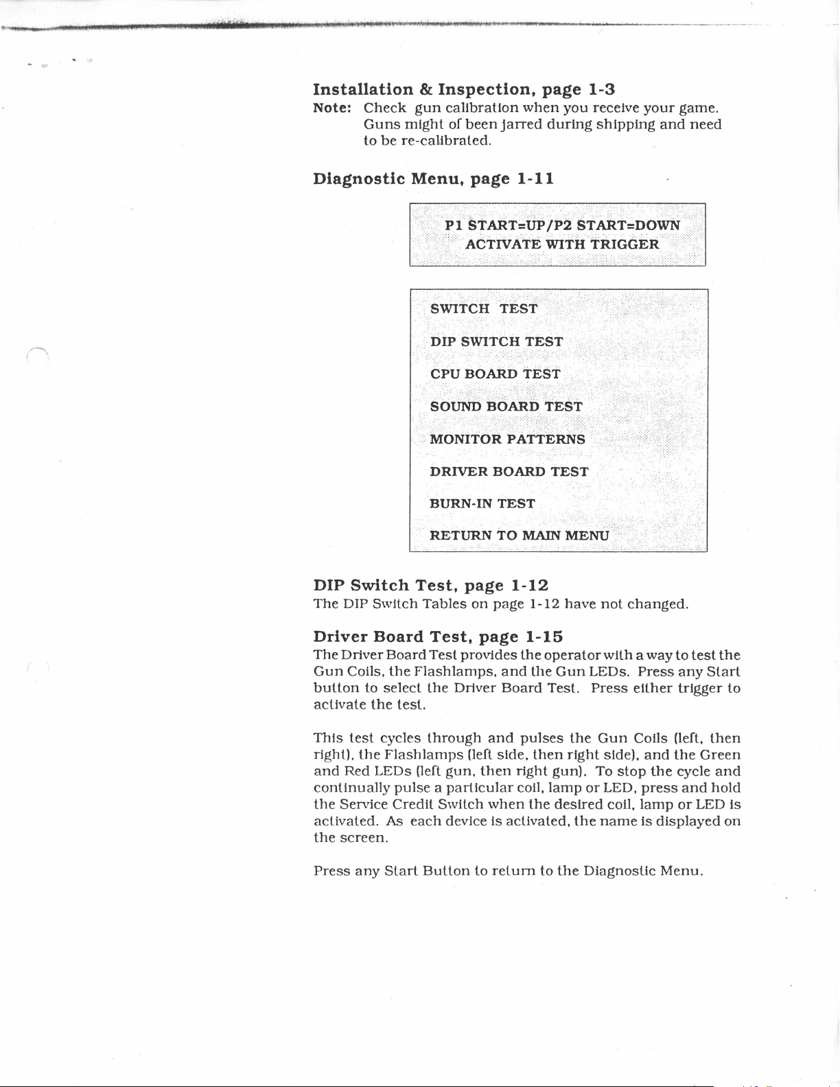
Driver
The
Gun
button
activate
This
right).
and
Board
Driver
Coils,
to
the
test
the
Red
LEDs
continually
the
Service
activated.
the
screen.
Press
any
Test,
Tables
page
on
Test,
Board
select
cycles
Flash
As
Start
Test
provides
the
Flashlamps,
the
Driver
test.
through
lamps
(left
(left
gun,
pulse a particular
Credit
each
Button
Switch
device
to
page
page
and
Board
and
side,
then
when
is
activated,
return
1-12
1-12
1-15
the
the
pulses
then
right
coil,
the
to
have
operator
Gun
LEDs.
Test.
Press
the
right
gun).
lamp
or
desired
the
the
Diagnostic
not
changed.
with a way
Press
either
Gun
Coils (left,
side).
and
To
stop
LED,
press
coil,
lamp
name
is
to
test
any
trigger
the
Green
the
cycle
and
or
LED
displayed
Menu.
the
Start
to
then
and
hold
is
on

You
need
two
For
a single
inserted.
For a two
player
Player 2 Start
Press
the
trigger
Pick-up
"Power-ups"
credits
player
game,
Buttons
to
to
start a game,
game
press
press
after
shoot
at
by
shooting
either
either
coins
targets.
TERMINATOR
Game
and
one
credit
of
the
Red,
of
the
Red, Player 1
have
been
inserted.
Press
the
Red
them.
2
Rules
to
continue.
Player 1 Start
Start
Bomb
Button
Buttons
Buttons
on
the
after
and,
gun
coins
either
to
launch
have
of
the
rockets.
been
Blue,
I~
I
Mission
In
the
1
future
Machines
Generator.
Mission
In
the
2
present.
all costs!
...
Join
of
Skynet.
..
Sent
Destroy
up
with
Sgt.
Infiltrate
back
through
Cyberdyne
John
Skynet
the
Systems
Connor -leader
Headquarters
Time Field
to
save
Generator
the
world from
of
the
to
ultimately
Human
control
to
protect
Judgment
Resistance -to
the
Time
young
John
Day!
destroy
Field
Connor
the
at
(
MIDWAY
AND
THE
MANUFACTURING COMPANY RESERVES
IMPROVEMENTS TO ITS PRODUCTS.
SPECIFICATIONS AND
PAITTS
CHANGE WITHOUT NOTICE.
IDENTIFIED
IN
THE
RIGHTS TO MAKE MODIFICATIONS
THIS
MANUAL
ARE
SUBJECT
c
TO
~-/
( ·
, I
( )
Ter1ninator
2
Section 1 Operation
Safety
Set-up
Servicing
Game
Game
Menu
Utilities
Calibrate
Trotlbleshooting
..................................................................................................................... 1-2
Procedure
Installation
I...ocation
Front
Rear
Features
Cabinet
Cabinet
...................................................................................................................
Starting-up
Player
Controls............................................................................. 1-8
Control
Operation
Control
Control
System
Operation
Main
Menu
Diagnostic
Coin
Bookkeeping........................................................................
Game
Game
Audits................................................................................ 1-1 7
Adjustments
Standard
Custom
........................................................................................................
Guns
TABLE
& Inspection........................ . . . . . . . . . . . . . . . . . . . . . . . . . . . . . . . . . . . . . 1-3
Requirements
Assembly
Assembly
OF
CONTENTS
and
Troubleshooting
.................................................................
Diagram.................................................
Diagram
................................................... 1-5
1-3
1-4
1-6
................................................................................... 1-8
Panel
Diagram
.................................................................. 1-8
Switches.......................................................................... 1-9
Switch
Operation
I...ocation Diagram................................................. 1-9
..................................................................................... 1-1 O
..................................................................................
Tests
........................................................................... 1-11
Switch
DIP
CPU &
Monitor
Burn-in
Test
Switch
Sound
Patterns
Test
............................................................
Test & Table
Tests
.............................................
...........................................................
'.
........... 1-11
~......
...............................................................
......................................................................
.......................................................................
Pricing Table .................................................................
Pricing Table ...................................................................
........................................................................................
......................................................................................................
1-10
1-12
1-13
1-14
1-15
1-16
1-19
1-22
1-23
1-24
1-25
1-26
Cabinet,
PC
Boards,
Cables
Power
CPU
Sound
Coil
Gun
Dual
CPU
Dual
Sound
Coil
......................................................................................................
Supply
Board
Board
Lamp
Assembly
Flashlamp
Board
Flashlamp
Board
Lamp
JAMMA
Cabinet
Control
©Copyright
Section 2 Parts
Speaker,
Transformer & Lamp
Manuals,
& Monitor .....................................................
Information
Assy, &
Control
Panel. ...........................
...........................................................................................
............................................ : ..................................................
............................................................................................
Driver
Board
............................................................................
..........................................................................................
& LED
Section 3 Diagrams
Boards
.................................................................
and
Schematics
...............................................................................................
& LED
Boards
.................................................................
............................................................................................
Driver
Chart & Power
Wiring &
Panel
1991
Board
............................................................................
Main
Wiring
Harness
Diagram
....................................................
Wiring ....................................................
Wiring ................................................................................
MIDWAY
Manufacturing
Company
2-2
2-3
2-4
2-5
2-6
2-8
2-10
2-12
2-14
3-2
3-18
3-19
3-23
3-26
3-27
3-28
( I
Term.iriator
SECTION
2
one
i •
Operation
\
1-1
The
following
nel. Specific
they
apply. We
safety
instructions
warnings
recommend
Safety
and
cautions
that
Notices
apply
will
you
read
to
be
all
game
found
this
operators
throughout
page
before
and
seIVice
this
manual
preparing
person-
your
where
game
for play.
BIDBI~:!'.!!~!'=lllillf•IP.Jll1If1P1J
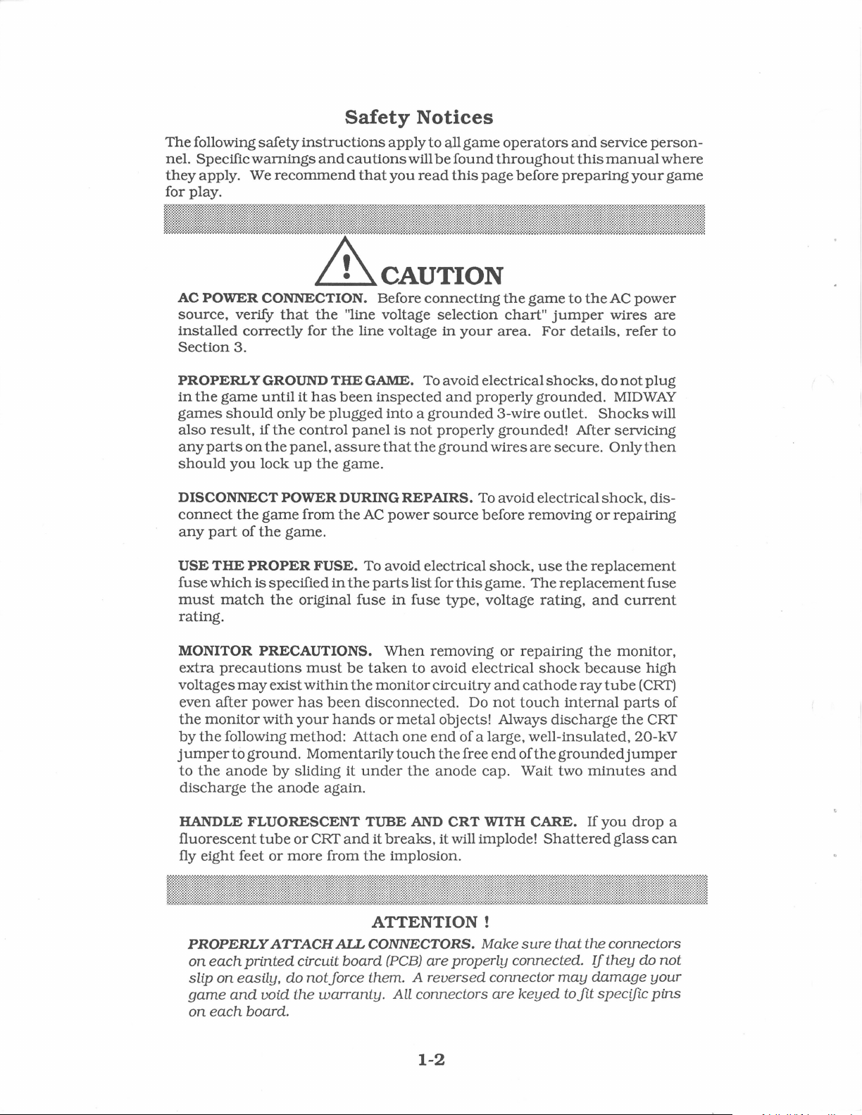
AC POWER CONNECTION. Before
source,
installed
Section
PROPERLY GROUND
in
games
also
any
should
DISCONNECT POWER DURING
connect
any
USE
fuse
must
the
result,
parts
part
THE
which
verify
correctly
3.
game
should
on
you
the
of
PROPER
match
that
until
only
if
the
the
panel,
lock
game
the
game.
is
specified
the
the
for
the
THE
it
has
be
plugged
control
assure
up
the
from
FUSE.
in
original
"line voltage
line voltage
GAME. To avoid electrical
been
inspected
into a grounded
panel
is
not
that
game.
REP
the
AC
power
To avoid electrical
the
parts
list
fuse
in
fuse
rating.
MONITOR PRECAUTIONS.
extra
precautions
voltages
even
after
the
monitor
by
the
following
jump
er
to
to
the
anode
discharge
may
power
ground.
the
exist
with
by
anode
must
within
has
been
your
hands
method:
Momentarily
sliding
again.
When
be
taken
the
monitor
disconnected.
or
metal
Attach
one
touch
it
under
the
to
connecting
selection
in
your
and
properly
properly
the
ground
AIRS.
source
wires
To avoid electrical
before
shock,
for
this
game.
type,
voltage
removing
avoid electrical
circuitry
Do
and
not
objects! Always
end
of
a large,
the
free
end
anode
cap.
the
game
chart"
area.
jumper
For
shocks,
grounded.
3-wire
outlet.
grounded!
are
secure.
removing
use
The
rating,
or
repairing
shock
cathode
touch
discharge
well-insulated,
of
the
Wait
to
the
AC
wires
details,
do
refer
not
MIDWAY
Shocks
After seIVicing
Only
shock,
or
repairing
the
replacement
replacement
and
current
the
monitor,
because
ray
tube
internal
parts
the
grounded
two
jumper
minutes
power
are
to
plug
will
then
dis-
fuse
high
(CRT)
of
CRT
20-kV
and
HANDLE FLUORESCENT
fluorescent
fly
eight
PROPERLY
on
each
slip
on
game
on
each
feet
printed
easily,
and
board.
tube
or
or
more
ATTACH
circuit
do
void
the
CRT
and
from
AIL
board
notjorce
warranty.
TUBE
the
AND
it
breaks,
implosion.
CRT
it
will implode!
ATTENTION!
CONNECTORS.
(PCB)
are
properlu
them. A
reversed
All
connectors
1-2
WITH CARE. If
Shattered
Make
sure
that
the
connected.
connector
are
keyed
may
to
fit
you
drop
glass
connectors
If
they
damage
specific
do
a
can
not
your
pins
Setup
Procedure
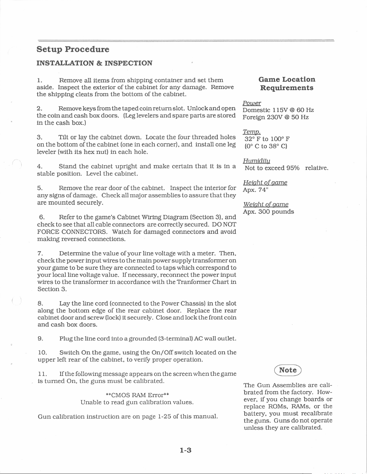
INSTALLATION & INSPECTION
(-'I
1. Remove all
aside.
the
Inspect
shipping
2. Remove
the
coin
and
cash
in
the
cash
box.)
3.
on
leveler (with
4.
stable
Tilt
or
the
bottom
its
Stand
position. Level
5. Remove
any
signs
of
damage.
are
mounted
6. Refer
check
to
see
that
items
the
exterior
cleats
keys
from
from
box
lay
the
of
the
cabinet
hex
nut)
the
cabinet
the
rear
securely.
to
the
game's
all
cable
doors. (Leg levelers
cabinet
Check
FORCE CONNECTORS.
making
7.
check
your
your
wires
Section
reversed
Determine
the
power
game
to
connections.
the
input
be
sure
local line voltage
to
the
transformer
3.
they
value.
from
of
the
the
(one
in
each
upright
the
cabinet.
door
Cabinet
connectors
Watch
value
wires
of
to
are
in
accordance
shipping
the
cabinet
bottom
taped
of
coin
container
the
return
down. Locate
in
each
hole.
and
make
of
the
cabinet.
all
major
assemblies
Wiring
are
for
damaged
your
line voltage
the
main
power
connected
If
necessary,
with
for
any
cabinet.
slot.
and
spare
the
corner).
certain
Inspect
Diagram
correctly
connectors
with a meter.
supply
to
taps
which
reconnect
the
Tranf
and
damage.
Unlock
parts
four
threaded
and
that
the
to
assure
(Section 3),
secured.
transformer
the
ormer
set
them
Remove
and
open
are
stored
holes
install
it
one
is
interior
that
they
DO NOT
and
avoid
Then,
correspond
power
input
Chart
Power
Domestic
Foreign
Temp.
320 F
leg
(Oo
in
Humiditu
a
Not
Height
for Apx. 7 4
Weight
Apx.
and
on
to
in
Game
Location
Requirements
l l
5V
@
230V @ 50
to
100° F
c
to
3go
C)
to
exceed
of
11
of
300
95%
game_
game
pounds
60
Hz
Hz
relative.
8. Lay
along
cabinet
and
9.
upper
is
Gun
cash
10.
11.
turned
the
door
box
Plug
Switch
left
If
the
On,
calibration
the
line
bottom
and
doors.
the
line
On
rear
of
following
the
Unable
cord
(connected
edge
of
screw
(lock) it securely. Close
cord
into a grounded
the
game,
the
cabinet,
message
guns
must
**CMOS
to
read
instruction
the
using
be
are
to
rear
cabinet
the
to
verify
appears
calibrated.
RAM
gun
calibration
on
page
the
Power
door. Replace
(3-terminal)
On/Off
proper
on
the
Error**
1-25
Chassis)
and
lock
the
AC
switch
located
operation.
screen
when
values.
of
this
manual.
1-3
in
the
front
wall
the
the
slot
rear
coin
outlet.
on
the
game
The
Gun
brated
ever,
if
replace
battery,
the
guns.
unless
Assemblies
from
the
factory. How-
you
change
ROMs, RAMs,
you
must
Guns
do
they
are
calibrated.
are
cali-
boards
or
the
recalibrate
not
operate
or
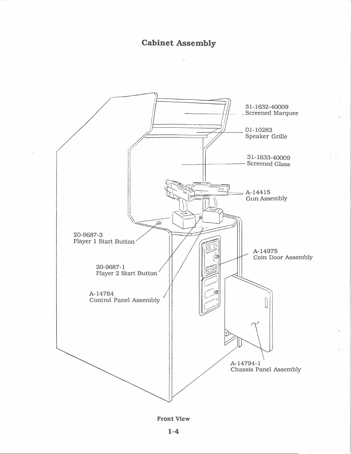
Cabinet
Assembly
---;;----
-·-·----
----
31-1632-40009
~
Screened
31-1633-40009
Screened
Marquee
Glass
20-9687-3
Player 1 Start
20-9687-1
Player 2 Start
A-14764
Control
Button/
Panel
Button
Assembly
A-14975
Coin
Door
Assembly
I
'\
ul
A-14794-1
Chassis
Panel
Assembly
Front View
1-4
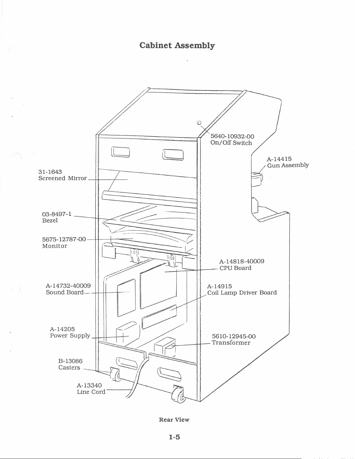
31-1643
Screened
Mirror
Cabinet
---4-f--~..---
L
Assembly
----
5640-10932-00
On/
Off
Switch
/
-.-....
---
A-14415
Gun
Assembly
5675-12787-00
Monitor
A-14
732-40009
Sound
Board
A-14205
Power
Supply
B-13086
Casters
A-13340
Line
_JH--t--===:::::____
---
-1..J..-1+---t-i·
-
Cord
---
A-14818-40009
CPU
Board
A-14915
~
Coil
Lamp
5610-12945-00
-Transformer
Driver
Board
Rear
1-5
View
To remove
bench
the
lea~e
sides
careful
through
you
Control
control
guns
glass.
the
panel
servicing,
coin
the
of
the
not
the
might
Board.
panel
rest
Disconnect
ground
out
(caution)
the
control
door
opening
latches
control
to
reach
coin
damage
Carefully, tilt
foiward
against
strap.
of
the
reach
located
panel.
straight
door
opening
the
the
the
cables
Lift
the
game
panel
for
through
and
re-
on
the
back
Monitor
the
until
the
viewing
and
control
cabinet.
Be
as
Servicing
•
Servicing
Switch Off
in
place
left
and
constant
reached
latches,
ers. Carefully,
Carefully, tilt
rest
against
DOESNOTHAVEASUPPORrBRACKET.
control
cluding
position, avoiding
•
Servicing
Switch Off
chassis
front
door
holds
the
the
front
Use
the
front
latch
door
the
the
power
by
four
right
pressure
through
lift
the
the
panel,
the
ground
the
power
panel
is
held
control
door,
handle
from
hand
Control
to
latches
sides
the
latch
use
the
control
the
of
on
coin
handle
the
Panel
game.
(located
the
control
the
strikes.
door
and
guns
panel
The
viewing glass. THIS CONTROL PANEL
check
is
can
hole
for
strap,
pinched
Chassis
to
the
game
accessible
in
place
panel.
be
reached
and
unhook
the
inside
to
slide
proper
and
use
wires.
Panel
and
through
by
the
The
latch,
through
the
of
the
the
chassis
control
inside
the
panel)
The
cabinet,
which
latches
opening. To
unhook
to
lift
foiward
the
the
control
until
Toreinstallthe
cable
the
guns
connections,
to
Reclamp
open
the
coin
the
front
same
type
located
the
coin
wire
fastner.
cabinet
and
panel
panel
provide
release
wire
the
lower
the
latches.
door.
door.
of
latch
at
the
door. Lift
Push
remove it.
foiward.
is
held
on
the
can
be
the
fasten-
panel.
guns
in-
it
into
The
The
that
top
the
of
The
monitor
an
isolation
chassis
the
Power
cated
on
When
THE
VOLTAGE
TRANSFORMER.
test
servicing
bench,
MONITOR
DOES
transf
(it is
mounted
Chassis
the.floor
YOU
WITH
(caution)
While
firmly
the
not
removing
support
front
slip.
of
the
CRT
NOT
armer
Assembly
of
the
the
monitor
MUST
FROM
AN
the
the
monitor
so
contain
in
its
instead
cabinet).
!SOI.ATE
THE
ISOI.ATION
four
that
in
lo-
on
UNE
bolts,
from
it
will
a
•
Removal
Switch Off
Carefully lift
clear
•
Removal
Switch Off
holding
four
monitor.
•
Monitor
We
recommend
oughly
Switch Off
viewing
nect
chassis
monitor's
the
power
of
the
the
screws
before
power
glass
the
monitor
ground
mounting
monitor
of
Viewing
to
the
game,
the
glass
from
cabinet.
of
Monitor
power
to
rear
door. Remove
holding
the
game. Remove
the
Replacement
that
you
read
beginning
to
and
the
strap.
carefully from
this
the
game. Remove
monitor
from all of
Remove
flanges
Glass
and
open
the
its
bottom
groove
Bezel
T-15
the
rear
door. Remove
bezel. Lift
the WARNINGS
procedure.
bezel. Completely
its
the
to
its
the
back
the
the
cabling,
four
bolts
mounting
of
the
control
panel.
and
torx
screws
bezel off
section
rear
door,
discon-
including
securing
panel.
cabinet.
lift
the
the
thor-
the
its
the
Pull
it
1-6

•
Flashlamp
Switch Off power
order
control
screws
mirror
are
mirror
•
Removal
Switch Off power
washer
cabinet.
marquee
carefully
The
Grasp
its
turn
•
Removal
to
panel.
holding
retainer
accessible from
is
out.
head
and
to
fluorescent
the
socket. Carefully place a
to
reinstall.
Assembly
Switch Off
Disconnect
cable. Remove
cabinet
and
Replacement
to
the
remove
Remove
tube,
power
the
Open
the
out
of
the
to
screws
the
the
clear
prevent
tube
give
of
the
to
the
fluorescent
the
lift
out
mirror
of
Marquee
in
damage.
it a quarter
the
screws
the
game.
viewing glass:
the
the
the
the
the
strip
glass.
is
now
Open
rear
door. Remove
retainer. Carefully,
cabinet.
front of
game. Remove
black
plastic
and
carefully lift
Store
the
accessible for
turn,
new
tube
Fluorescent
game. Remove
light
assembly
fastening
assembly.
the
then,
The
flashlamp
the
cabinet
strip
marquee
and
into
Light
the
the
control
the
remove
the
panel
replace
the
pull
boards
once
five
#8
on
top
the
and
replacement.
socket,
·
marquee
from
its
assembly
in
the
two
the
the
hex
of
the
plastic
glass
it
from
and
glass.
power
to
the
IH!lll!l!lll!l!l!lll!l~!l!l!l!l!l~!l~llllll!lll!l!l!lll!lllll!lll!l!l!l!l!llllllll!l!lllll!lllll!llllllll~!l~~l!l!llllll~l!l!HHl~!IHlll
WARNING
If
you
drop a fluorescent
and
it
breaks,
Use
care
llf
~~!llllllllll!lllllllll~IHl!l!l!llllllllllllllllllllllllllllllllllllllllllllllllllll!lllllll!lllllllllllllllllllllllllllllllllllllllllllllllllll~I
it will implode!
in
handling.
tube
•
Removal
Switch Off
speakers
to
disconnect
mounting
of
their
enclosure.
•
Volume
and
Service
Open
the
and
Diagnostic
box
cover.
end
of
the
the
volume.
Test/Diagnostics
Menu
testing
System.
Switch,
which
without
of
the
power
pull
bolts
to
out
from
the
before
Control,
Credit
coin
door
switches
The
Volume Control
panel.
The
The
allows
affecting
Turning
upper
Switch
Speakers
the
game. Remove
the
front
of
cabling
and
remove
attempting
to
Test/Diagnostics
Switch
to
locate
lower right
adding
the
game's
on
the
small
is
the
knob
right
switch
that
enables activating
switch
credits
the
game's
the
marquee.
the
cabinet. Be
the
nuts
on
pull
the
speakers
Switch.
volume
panel
the
white
clockwise
on
the
bracket
is
the
Service Credit
to a game
bookkeeping total.
control
atop
the
knob
increases
the
for service
game's
sure
cash
on
is
The
the
out
left
the
1-7
Game
Features
When
Start-up
pauses.
continue.
an
(Note)
error
is
Tests.
Press
any
detected
game
Start
start-up
Button
during
to
STARTING
Switch
CRT
CHECKING SCRATCH
The
CMOS TEST
moves
Insert
player
Start
On
screen.
next
to
the
receives
Button.
UP
power
When
screen
OK
the
Attract
desired
to
shows
and
amount
the
the
game. A "rug"
the
"rug"
RAMS.
the
Mode.
credit
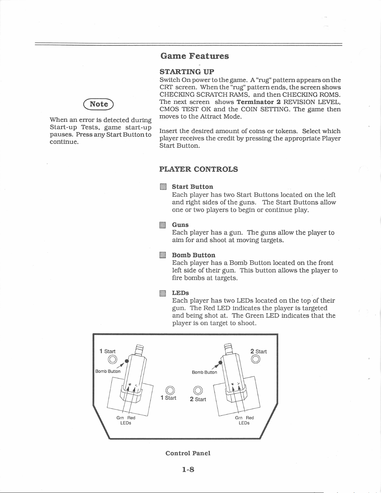
PLAYER CONTROLS
Billi
Start
Button
Each
[]
and
one
or
Guns
Each
aim
for
player
right
player
sides
two
and
has
two
of
the
players
has a gun.
shoot
to
at
pattern
pattern
Terminator
COIN SETTING.
of
coins
by
pressing
Start
guns.
begin
The
moving
ends.
and
then
or
the
Buttons
The
or
continue
guns
targets.
2 REVISION LEVEL.
tokens.
Start
appears
the
screen
CHECKING ROMS.
The
Select which
appropriate
located
Buttons
play.
allow
the
game
on
the
player
on
shows
then
Player
left
allow
the
to
filill]
Bomb
Each
left
fire
[ill
LEDs
Each
gun.
and
player
(Q)
1 Start 2 Start
Button
player
side
of
bombs
player
The
being
is
(Q)
has
their
at
targets.
has
Red LED
shot
on
target
a Bomb
gun.
This
two LEDs
indicates
at.
The
to shoot.
Button
button
located
Green
2 Start
(Q)
the
LED
located
allows
on
the
player
indicates
on
the
the
top
is
targeted
front
player
of
their
that
the
to
Control
1-8
Panel
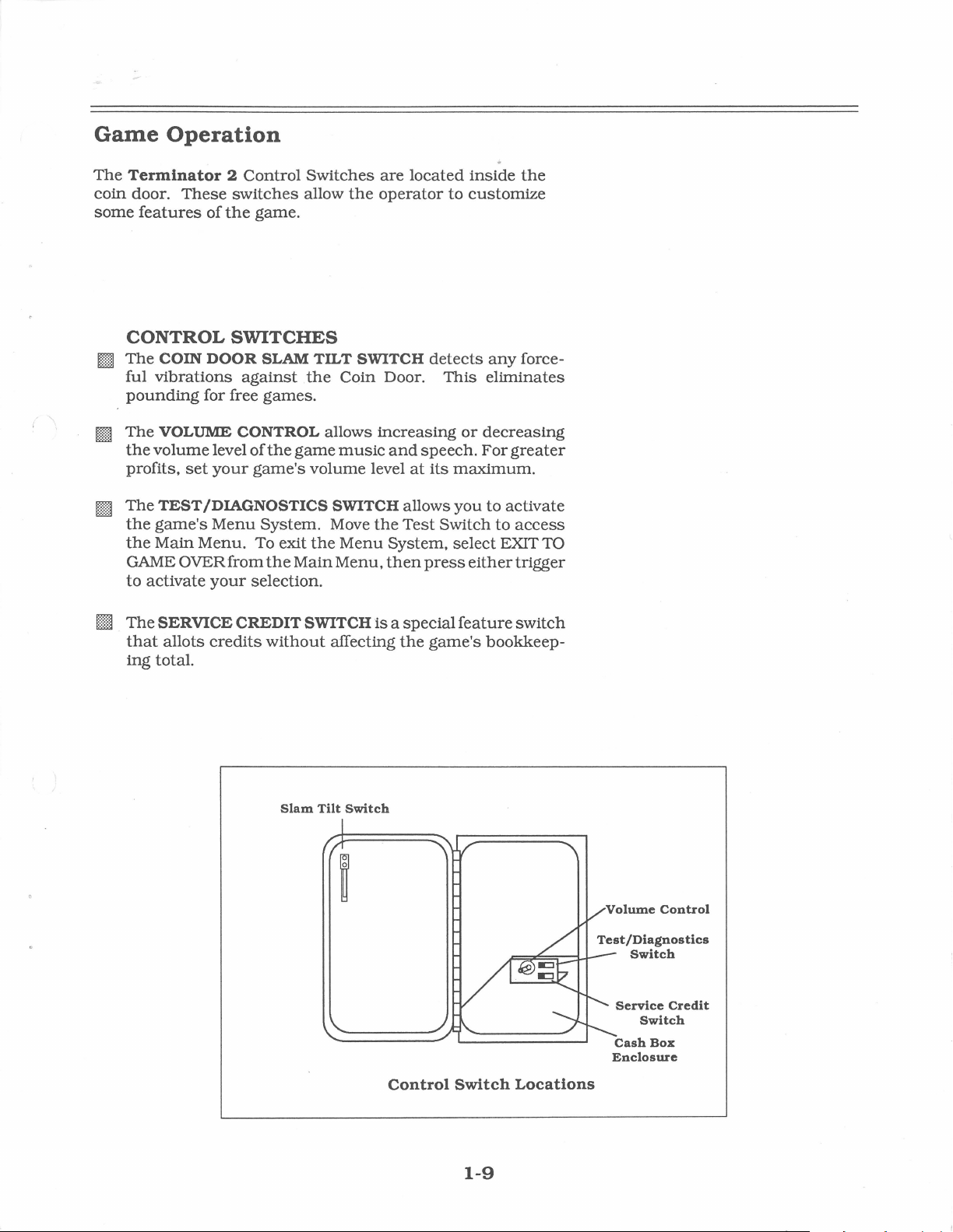
Game
The
coin
some
Operation
Terminator 2 Control
door.
These
features
of
switches
the
game.
Switches
allow
the
are
located
operator
inside
to
customize
the
CONTROL
§ill
The
ful
pounding
[I
The
the
profits,
rnJ
The
the
the
GAME OVER
to
activate
[ill
The
that
ing
SWITCHES
COIN DOOR SLAM TILT SWITCH
vibrations
VOLUME CONTROL allows
volume
set
TEST
game's
Main
SERVICE CREDIT SWITCH
allots
total.
against
for free
the
games.
Coin Door.
increasing
level
of
the
game
your
game's
music
volume
and
level
/DIAGNOSTICS SWITCH allows
Menu
Menu.
your
credits
System.
To exit
from
the
selection.
without
the
Main
Move
the
Menu
Menu,
System,
then
ls
affecting
Test
a special
the
detects
This
or
speech.
at
its
maximum.
you
Switch
select EXIT TO
press
either
feature
game's
any
force-
eliminates
decreasing
For
greater
to
activate
to
access
trigger
switch
bookkeep-
Slam
Tilt
Switch
Control
Switch
1-9
Locations
Volume
Service
Switch
Enclosure
Control
Credit
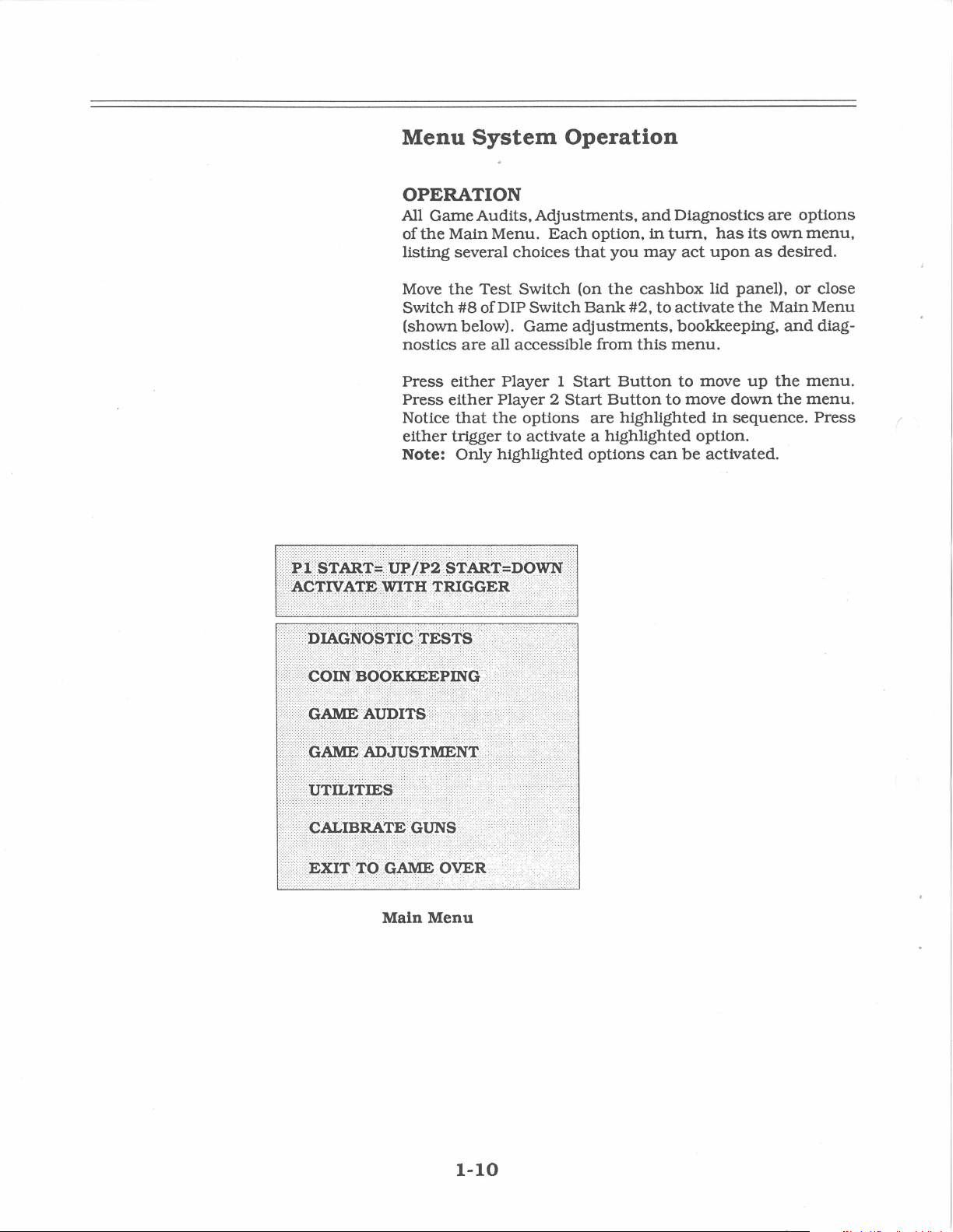
Menu
System
OPERATION
All
Game
Audits,
of
the
Main
Menu.
listing several
Move
the
Test
Switch
(shown below).
nostics
#8
of DIP Switch
are
all
Operation
Adjustments,
Each
choices
Switch (on
Game
accessible
that
Bank
adjustments,
option,
you
the
#2,
from
this
and
Diagnostics
in
turn,
may
act
cashbox
to
activate
bookkeeping,
menu.
are
has
its
own
upon
as
desired.
lid panel),
the
Main
options
menu,
or
close
Menu
and
diag-
~1
:
~1'Bf
.•
ACTlVAT~
§
trl>l~~
W'Jl'!:l
Press
Press
Notice
either
Note:
either
either
trigger
:
$~Bt#~C>~
·•
TRIGG.ER
Player 1 Start
Player 2
that
the
to
Only
highlighted
options
activate a
..
••··•·.:·•••·····
·······.·
..
Start
Button
are
highlighted
options
!:>
Button
highlighted
to
can
to
move
option.
be
move
up
down
in
sequence.
activated.
the
the
menu.
menu.
Press
Main
Menu
1-10
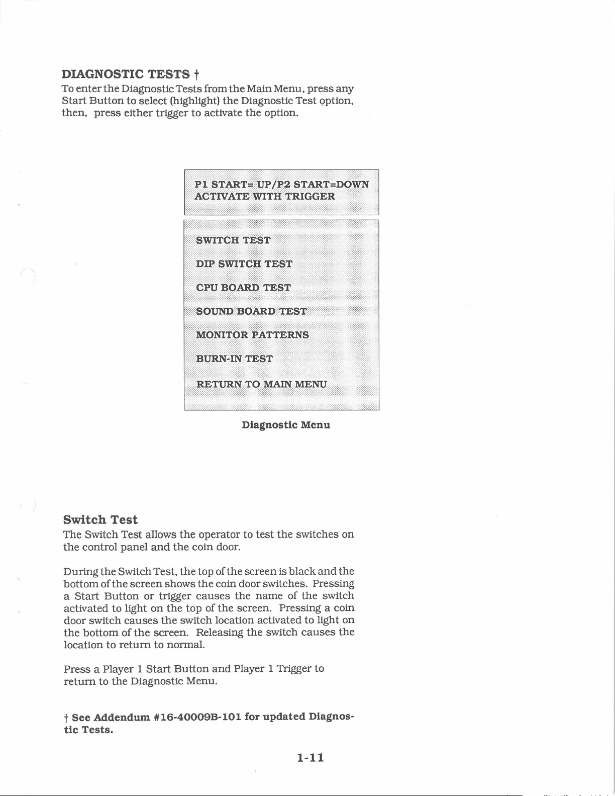
DIAGNOSTIC
To
enter
the
Diagnostic
Start
then,
Button
press
to
either
TESTS
select (highlight)
trigger to activate
t
Tests
from
the
Main Menu,
the
Diagnostic Test Qption,
the
option.
press
any
Switch
The Switch Test allows
the
During
bottom
a
Start
activated
door switch
the
location to
Press
return
Test
control
the
of
the
Button
to
bottom
a Player 1
to
the
panel
Switch Test,
return
and
screen
light
causes
of
the
Diagnostic Menu.
shows
or trigger
on
the
the
screen. Releasing
to
normal.
Start
Diagnostic
the
operator to
the
coin door.
the
top of
the
coin door switches. Pressing
causes
top of
switch location activated to light
Button
the
and
test
the
screen
the
name
screen. Pressing a coin
the
switch
Player 1 Trigger
the
is
black
of
Menu
switches
and
the
causes
to
on
the
switch
on
the
t
See
tic
Tests.
Addendum
#16-40009B-101
for
updated
Diagnos-
1-11
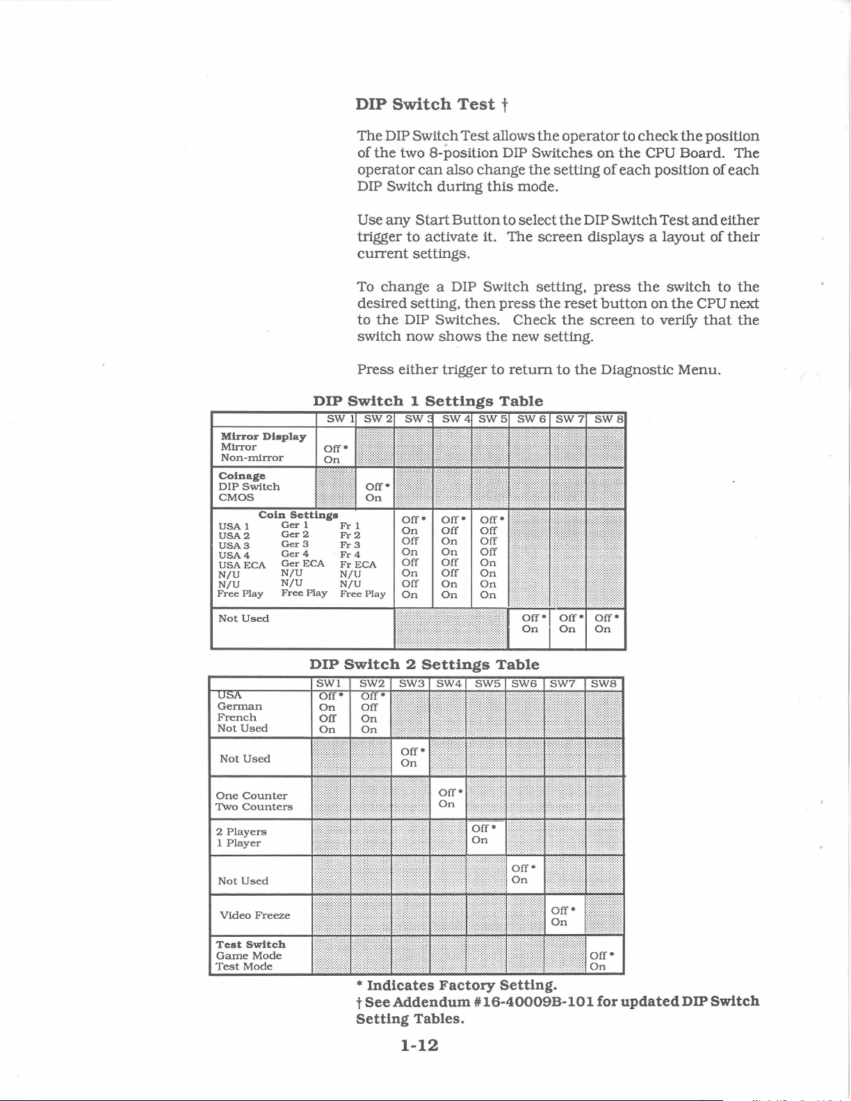
DIP
DIP
Switch
The
DIP Switch
the
of
two 8-position DIP
operator
DIP Switch
Use
any
trigger
current
To
change
desired
to
the
DIP Switches.
switch
Press
Switch
now
either
Test
can
also
during
Start
Button
to
activate it. The
Test
change
t
allows
this
to
mode.
select
settings.
a DIP Switch setting,
setting,
then
press
Check
shows
1
Settings
trigger
the
to
Table
new
return
the
operator
Switches
the
setting
the
screen
the
reset
the
setting.
to
the
to
check
on
the
of
each
DIP Switch
the
CPU Board. The
position
Test
displays a layout
press
screen
the
button
on
to
switch
the
verify
Diagnostic Menu.
position
of
each
and
either
of
their
to
CPU
that
the
next
the
Mirror
Mirror
Non-mirror
Coinage
DIP
Switch
CMOS
USA
1
USA2
USA3
USA4
USAECA
N/U
N/U
Free
Play
Not
Used
German
French
Not
Used
Not
Used
One
Counter
Two
Counters
2
Players
1
Player
Display
Coln
Settings
Gerl
Ger2
Ger
3
Ger4
Ger
ECA
N/U
N/U
Free
Play
DIP
Frl
Fr2
Fr
3
Fr4
Fr
ECA
N/U
N/U
Free
Play
Switch
2
Settings
Table
Not
Video
Test
Game
Test
Used
Freeze
Switch
Mode
Mode
*
Indicates
t
See
Addendum#
Setting
Tables.
1-12
Factory
Setting.
16-40009B-101
for
updated
DIP
Switch
CPU
Board
The
CPU
operator
Select
either
Board's
pattern
show
chip
CPU
Any
installed
tum
Pre~s
the
trigger
the
that
and
chip
green;
either
Test
Board
to
check
CPU
to
RAMs
appears
and
layout
is
shown
should
that
in
the
they
trigger
is
Test
the
Board
activate
RO Ms.
on
the
of
the
as
tum
shown
game.
are
to
(much
RAMs
Test
When
screen.
RAMs,
black
either
as
During
faulty,
exit
like
and
with
the
with
red
gray
the
if
back
they
the
Start-up
ROMs.
any
Start
Button
automatic
this
test
is
The
screen
and
RO
Ms
a white outline
or
green
during
with a white
test,
chips
turn
red.
to
the
Diagnostic Menu.
Test) allows
then,
test
of
activated, a "rug"'
then
changes
on
the
CPU. Any
is
part
the
outline
are
good,
the
press
the
CPU
to
of
the
CPU Test.
is
not
if
they
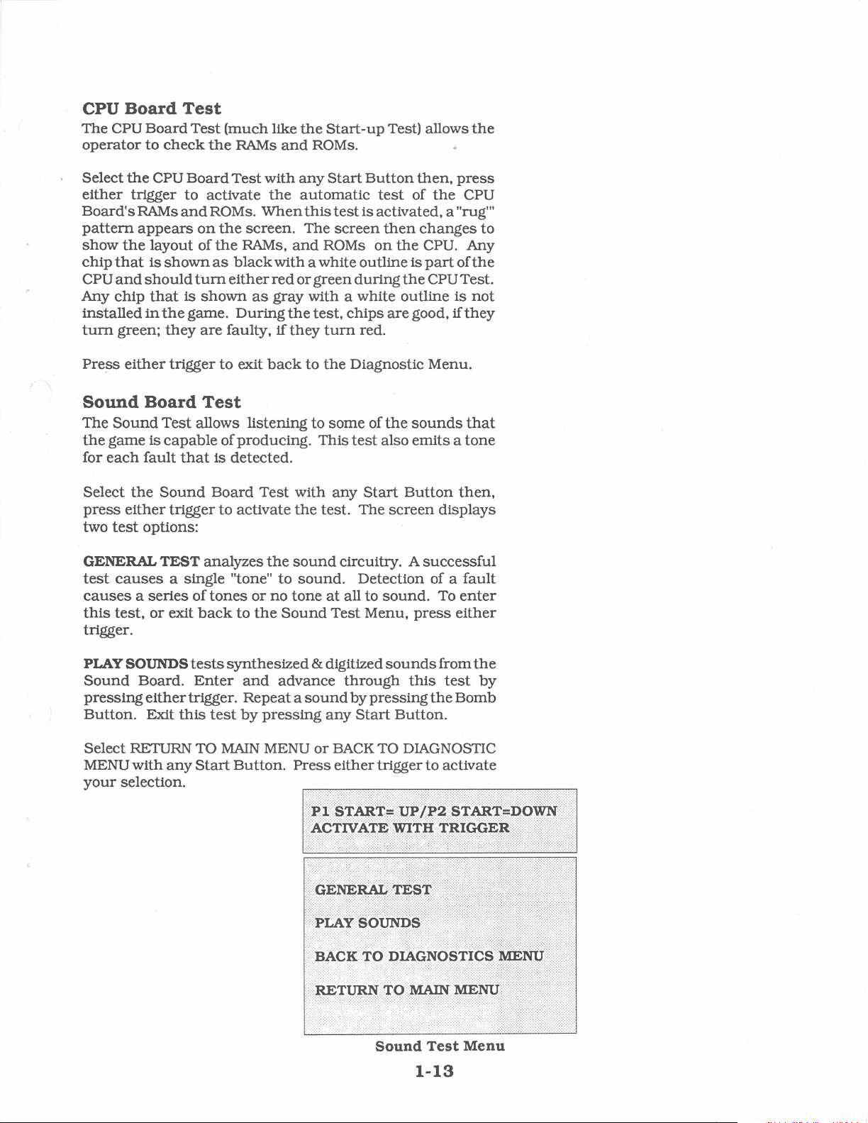
Sound
The
the
for
Select
press
two
GENERAL
test
causes a series
this
trigger.
PLAY SOUNDS
Sound
pressing
Button.
Select RETURN TO
MENU
your
Board
Sound
game
is
each
fault
the
either
test
options:
causes
test,
or
Board.
either
Exit
with
selection.
Test
Test
allows listening to
capable
that
Sound
trigger
TEST
analyzes
a single "tone"
of
exit
back
tests
Enter
trigger.
this
any
Start
of producing.
is
detected.
Board
tones
test
Test
to
activate
the
to
or
no
to
the
synthesized
and
advance
Repeat a sound
by
pressing
MAIN
MENU
Button.
some
of
the
This
test
also
with
any
Start
the
test. The
sound
tone
Sound
Press
circuitry. A
sound.
& digitized
or
i:i
~i
••••
ACl'nl'AT~
Detection of a
at
all to
sound.
Test
Menu,
sounds
through
by
pressing
any
Start
BACK
either
!
TO DIAGNOSTIC
trigger
~iBx§
sounds
emits a tone
Button
screen
successful
press
this
Button.
::
~~2~~
IDTJJ
that
then,
displays
fault
To
enter
either
from
the
test
by
the
Bomb
to
activate
~'I'Bx#~<>lrl
!RlAP~R,
•
>••>•······
::>
····'·
Sound
Test
1-13
Menu
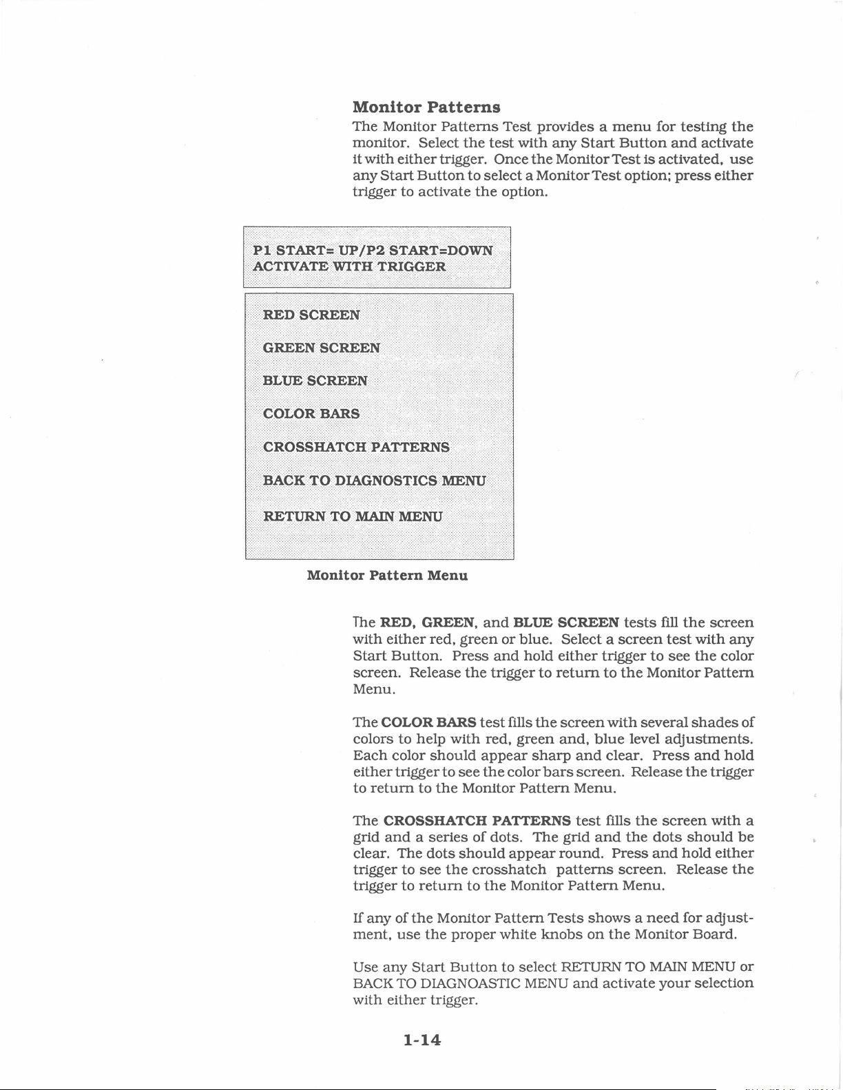
Monitor
The Monitor
monitor. Select
it
with
any
Start
Patterns
either
Button
Patterns
the
trigger. Once
trigger to activate
Test
provides a
test
with
the
to
select a Monitor
the
option.
any
Start
Monitor
Test
menu
Button
Test
option;
for
testing
and
is
activated,
press
the
activate
use
either
!
Monitor
The
with
Start
screen.
Menu.
The
colors to
Each
either
to
The
grid
clear. The
trigger
trigger
If
ment,
Use
BACK
with
Pattern
RED, GREEN,
either
COLOR
return
CROSSHATCH PATTERNS
and a series
any
any
Menu
red,
Button.
Release
help
color
should
trigger
to
dots
to
see
to
return
of
the
use
the
Start
green
Press
the
BARS
test
with
appear
to
see
the
Monitor
of
should
the
crosshatch
to
Monitor
proper
Button
and
BLUE
or
blue. Select a
and
hold
trigger
fills
red,
green
the
color
Pattern
dots.
appear
the
Monitor
Pattern
white
to
select RETURN TO
TO DIAGNOASTIC MENU
either
trigger.
SCREEN
either
to
return
the
screen
and,
sharp
bars
The
round.
patterns
Tests
knobs
screen
trigger
to
the
with
blue
and
clear.
screen.
Menu.
test
fills
grid
and
Press
screen.
Pattern
shows a need
on
the
and
activate
tests
fill
the
test
with
to
see
the
Monitor
several
level
Press
Release
the
screen
the
dots
and
Pattern
shades
adjustments.
and
the
should
hold
Release
Menu.
for
Monitor Board.
MAIN
your
MENU
selection
screen
any
color
of
hold
trigger
with a
be
either
the
adjust-
or
1-14
Burn-in
The
Burn-in
Press
any
either
detects
on
in
mittent
To exit
trigger
an
the
screen.
cycles
CPU problems.
this
Test
Test
continually
Start
Button
to
activate
error.
the
test
The
Audit
successfully
test.
switch
repeats
to
select
the
Burn-in
the
test.
When
stops
and
displays
Table specifies
completed. Use
the
game
Off
the
the
this
then
CPU
Board
Test;
the
Burn-in
an
error
number
test
to
On
again.
Test.
then.
message
of
Burn-
find
press
Test
inter-
1-15
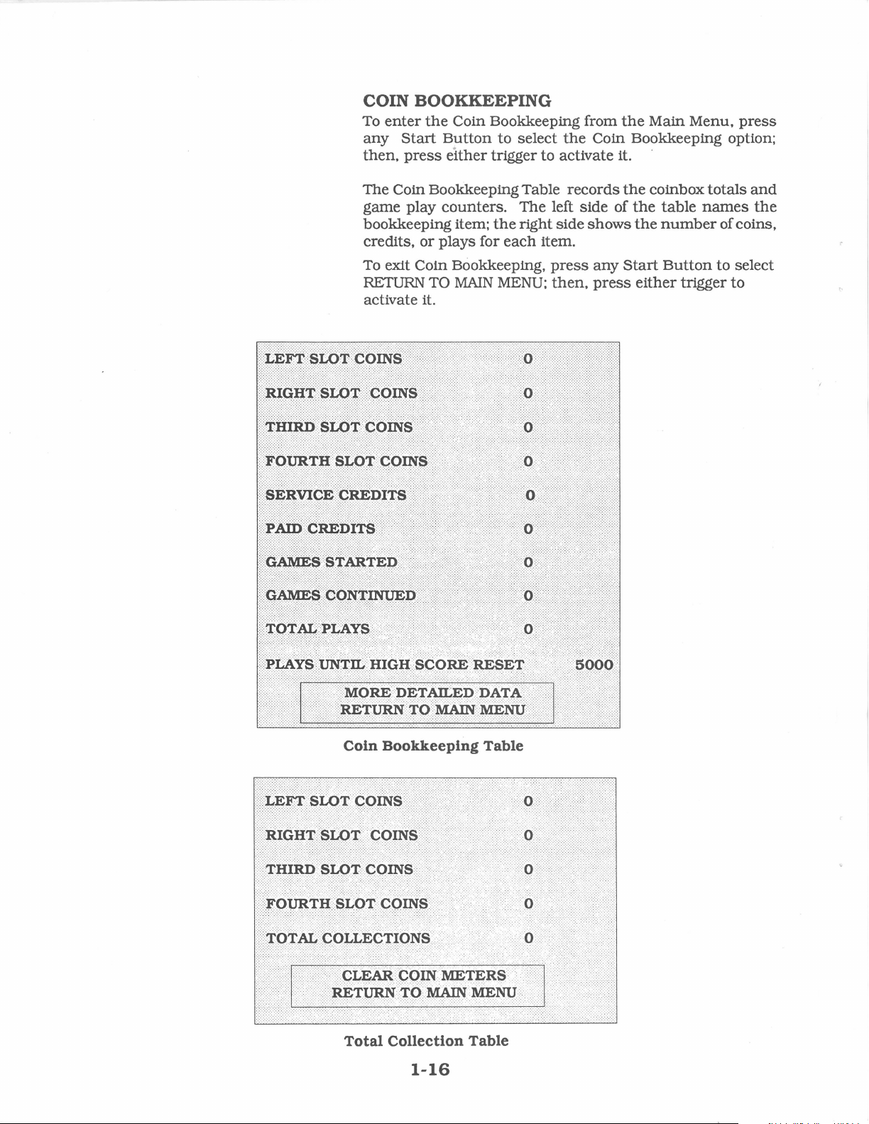
COIN BOOKKEEPING
To
enter
the
Coin Bookkeeping from
any
Start
then,
press
Button
either
to select
trigger to activate it.
the
Main Menu,
the
Coin Bookkeeping option;
press
The Coin Bookkeeping Table
game play
bookkeeping item;
credits,
To exit Coin Bookkeeping,
RETURN
counters.
or
plays for
TO
MAIN
The
the
right side
each
MENU:
left side of
item.
press
then,
activate it.
records
shows
any
press
the
coinbox
the
the
Start
either
totals
table
names
number
Button
trigger
and
the
of coins,
to
select
to
Coln
Bookkeeping
Total
Collection
Table
Table
1-16
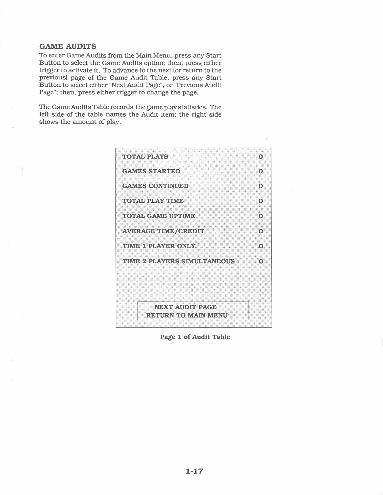
GAME AUDITS
To
enter
Button
trigger
previous)
Button
Page";
The
left
shows
to
to
to
then,
Game
side
the
Game
Audits
select
activate it. To
page
select
Audits
of
the
of
either
press
Table
the
table
amount
from
Game
advance
the
Game
"Next
either
records
names
of play.
the
Audits
Audit
Audit
trigger
the
Main Menu,
option;
to
the
Page",
to
change
the
game
Audit item;
then,
next
Table,
or
play
press
press..
(or
return
press
the
any
"Previous
page.
statistics.
the
right
any
Start
either
to
the
Start
Audit
The
side
Page 1
of
Audit Table
1-17

GAME
AUDITS
Continued
Page 2 of
Page 3
of
Audit
Audit Table
Table
To exit
select
RETURN TO
activate
the
your
1-18
Game
selection.
Audit
MAIN
Table,
MENU;
press
then.
any
press
Start
either
Button
trigger
to
to

GAME
Press
any
on
the
ADJUSTMENTS
Start
Button
Main Menu;
to
then,
select
press
the
Game
either
Adjustment
trigger
to
option
actlv~te
it.
the
Game
has
next
you
that
Press
then,
Pressing
value.
the
your
Adjustments
Game Pricing
Adjustments
its
own
then,
press
menu
wish
item.
any
press
Pressing
value.
Adjustments
selection.
The Game
change
The
option
an
option;
On
the
the
item
activate
choice.
value;
value.
setting
the
setting
To exit
select RETURN TO
activate
menu.
screen,
to
The
Start
either
the
Player 1
MAIN
Menu
either
modify;
Button
the
allows
and
Game DilTiculty.
Menu
offers several options.
Press
trigger
press
then,
activated item provides a
trigger to lock
Player 2
Menu,
MENU;
any
any
to
change
Start
press
then,
the
owner/
Start
Button
to
activate
Start
Button
press
Start
:
'\
either
the
in
the
Button
Button
any
Start
press
:\
~!
·
~+Ii
AC'I.'lV.t\T&
operator
Each
to
select
that
option.
to
select
trigger
setting
current
increases
either
setting
new
setting
decreases
Button
trigger
'.
~
11~~
Wl'l.'lf
to
to
the
to
to
$!1-t~~r,m
'J'lU@~R
..
::::u
•'·'••<•''•'•,
.......
·.
Game
Adjustment
1-19
Menu

GAME
ADJUSTMENTS
Continued
Standard
Standard
Pricing
Pricing allows
"Standard" selections for
Note: DIP Switch
made
from
Custom
Custom
than
allows
per
the
Note: DIP Switch
made
Free
This
settings
Pricing
Pricing allows
that
of
the
operator
game,
the
amount
from
Play
option
for
No
-
-Yes
Game
The
settings
Difficulty
operator
for
Easiest
- 1
- 5
Medium
10
-
settings
the
Game
the
Standard
amount
of
credits
the
Game
allows
the
adjustment
(factory)
.
chooses
this
adjustment
Hardest
Adjustment
to select
of
required
settings
Adjustment
the
the the
(factory)
the
operator
the
Standard
override
the
operator
Pricing Table.
the
maximum
credits
required
to
override
operator
are:
difficulty level
are:
to
choose
Pricing Table.
Standard
Pricing
Menu.
to
install
Custom
amount
to
start a game,
continue
Custom
a game.
Pricing
Menu.
to
select free play.
of
the
any
of
changes
pricing
other
Pricing also
of
credits
changes
game.
the
and
The
The
Energy
The
each
range
Per
operator
time
for
- 5 Lowest
-
-
Bombs
The
each
range
Per
operator
time
for
- 1 Lowest
-
-
Minimum
The
operator
player
range
is
for
-
-
-
*Not
in
effect
example,
Play
chooses
he/
she
starts
this
adjustment
100
Medium (factory)
200
Highest
Play
chooses
he/she
this
25
(factory)
99
Highest
Time
starts
adjustment
Per Play*
chooses
guaranteed
this
adjustment
30
Lowest
45
(factory)
300
Highest
during
Tank
Hunter
the
amount
or
of
energy a
continues
player
a game.
The
is:
the
amount
or
of
bombs a player
continues
a game.
The
is:
the
minimum
to receive for
time
each
in
play.
seconds
The
is:
end-of-wave confrontations:
Killer.
receives
setting
receives
setting
each
setting
For
1-20

Attract
The
during
Mode
operator
the
are:
-
On
-
Off
Auto
High
The
All -time High
time
this
adjustment
-
Off
-
250
5000
-
-25,
High
Score
The
operator
Score
ment
Entry
are:
No
-
- Yes (factory)
Sound
determines
Attract
(factory)
Score
many
plays
is:
Lowest
(factory)
000
Highest
Entry
determines
and
Table
Mode.
Reset
Score
whether
The
Table
occur.
whether
display.
the
settings
is
reset
The
the
The
settings
game
for
to
factory
setting
game
will
make
sounds
this
adju~tment
values
range
for
will allow High
for
the
adjust-
each
this
Allow
The
continue
to
Continue
operator
after
adjustment
- Never
-
Sometimes
- Always (factory)
determines
all
the
are:
whether
players
are
the
game
dead.
allows a
The
setting
player
for
this
to
1-21

Standard
Pricing
Table
t
NAME
USA
1
USA2
USA3
USA4
USA5
USA6
USA7
USA8
USAECA
German
German
German3
German
German
France
France
France
France
France
France
France
France
France
France
France
France
France
Canada
Swiss
1
Swiss
2
Swiss
3
Italy
UK 1
UK2
UKECA
UKw/CCU
Spain
1
Spain
2
Australia
Australia
Japan
Japan
2
Austria
Austria
Belgium
Belgium
Belgium
Beleium
Sweden
New
Zealand
New
Zealand
Netherlands
Finland
Norway
Denmark
Antilles
If
option
t
See
Addendum
1
2
4
ECA
1
2
3
4
5
6
7
8
9
10
11
12
ECA
1
2
1
1
2
1
2
3
ECA
desired
SETTING
Credit/Coin
1/25¢
1/50¢
1/50¢,
3/$1.00
1/50¢,
4/$1.00
1/25¢,
4/$1.00
1/50¢,
2/$1.00
1/50¢,
3/$1.00
1/50¢,
4/$1.00
1/25¢,
4/$1.00
l/lDM.
l/lDM, 7 /5DM
l/lDM,
l/lDM,
l/
lDM,
2/5F,
5/lOF
2/5F,4/10F
l/5F,3/10F
l/5F,
2/lOF
2/5F,
5/lOF.
2/5F,
4/lOF,
l/5F,
3/lOF, 7 /2 x lOF
l/5F,
2/lOF,
1/3 x lF,
1/2 x lF,
1/3 x lF,
1/2 x lF.
1/3 X lF,
1/2 x 25¢,
l/1F,6/5F
l/lF, 7 /5F
l/1F,3/5F
1/500
Ure
l/20P,3/50P
2/20P,5/50P
l/30P,
2/50P,
l/30P,
2/50P,
1/25
Peseta,
I/25
Peseta,
1/3 x 20¢,
1/5 x 20¢,
1/100
Yen
2/100
Yen
l/5Sch,
1/2 x 5Sch,
I/20F
3/20F
2/20F
1/25F,
4/lOOF
1/3 x lKr,
1/3 x 20¢
1
1/2 x 20¢
2
1/lHfi
, 3/2.51-lfi
l/lMka
1/2 x IKr.
1/2 x lKr,
1/25¢,
4/1
is
not
shown
#16-40009B-101
6/5DM
8/5DM
5/5DM
2/2DM,
6/5DM
11/2 x lOF
9/2 x lOF
5/2 x lOF
2/5F
3/5F
2/5F,
5/2 x 5F
3/5F. 7 /2 x 5F
2/5F,
5/2 x 5F
3/$1.00
4/£1.00
4/£1.00
5/
100
Peseta
4/100
Peseta
2/$1.00
1/$1.00,
2/lOSch
2/5Kr
3/5 x IKr
3/5Kr, 7 /2 x 5Kr
Guilder
3/$2.00
3/2 x lOSch
above,
use
LEFT CENTER
CHUTE
25¢
25¢ 25¢
25¢ 25¢
25¢
25¢
25¢
25¢
25¢
$1.00
lDM
lDM
lDM
lDM
5DM
5F
5F
5F
5F
5F
5F
5F
5F
lF
lF
IF
IF
lF
25¢
lF
lF
u~
500
20P
20P
£1.00
CCU
25
Peseta
25
Peseta
20¢
20¢
100
100
5Sch
5Sch
20F
20F 20F
20F
50F
lKr
20¢ 20¢
20¢
nlfi
1Mka
lKr
lKr
25¢
custom
pricing
for
CHUTE
Ure
Yen
Yen
.
updated
$1.00
$1.00
$1.00
$1.00
10¢
lDM
lOF
20P
5F
Standard
RIGHT
CHUTE
25¢
25¢
25¢
25¢
25¢
25¢
25¢
5DM
5DM
5DM
5DM
2DM
lOF
lOF
lOF
lOF
lOF
lOF
lOF
lOF
5F
5F
5F
5F
5F
$1.00
5F
5F
5F
500
Ure
50P
50P
50P
100
Peseta
100
Peseta
$1.00
$1.00
lOOYen
lOOYen
lOSch
lOSch
20F
20F
20F
5Kr
20¢
2.5Hfi
1Mka
lKr
5Kr
1
Guilder
FOURTH
CHUTE
5¢
10
p
Pricing
Table.
1-22

Custom
......
>
P:is±SR'l'#.
:
.AcXJ:Y.t\i'~
·;
WJ.I.n
Pricing
·.·.
··.·.·.·.·.·.
·.-
...
··.·.··.·.·.·.·.·.·.
.....
w'Zr.~
··
· ·
.·:-~::--:··
·
·
sl'AR-1'¥.voWH
TR~QG~R
:
. : > <
·,
>>
(1)
fies
"units
(2)
(3)
have
(4)
Coins
the
number
I credit").
This
One
accumulated.
No
credits
accumulated.
(5)
(6)
(7)
based
display
(8)
inserted
Each
Each
The
on
of
This
will
this
money
inserted
of
is
the
bonus
player
player
detailed
many
accumulate
units
given for
number
credit
will
needs
needs
of
is
be
awarded
this
this
bookkeeping
coins
per
coin
awarded
many
many
dollar. (Set
totals)
is
the
limit for
be
lost. (factory setting: 30)
the
credits
units.
each
units
until
screen
This
coin
in
required
after
this
this
credits
credits
shows
to
counter.
adjustment
the
fourth
to
many
many
to
begin a game.
to
continue a game.
total
zero
chute
buy
one
coin
coin
units
collections
to
disable
Additional
1-23
speci-
(see
credit.
units
have
the
coins

UTILITIES
Press
Main
Menu:
The
Utilities
game's
sage.
any
Start
Button
then,
Menu
bookkeeping
·.·.·.·.·.·.·.·.·.·.·.·.·.·.·.·.·.·.·.·.
.::
· :
s£¥
:::
n~£ttA.¥o:«
·\/f
/~//1)\jlj1\\H/Y?\\))\;i})/i\/?HU?i/1\??1////t/HiH\j//iUi/\i
.
:Otr.Atit.it:ABJtistMitNtS
..
:::::::::::::::::::::::::::::::::::::::::::::::::::::::::::
to
select
press
either
allows
memory
·.·
.·.·.·.·.·.·.·.·.·.·.·.·.·.·.·.·.·.·.·.·.·.·.·.·.·.·.·.
:
::::::::::::::::::::::::::::::::::::::::::::::::::::::::::::.::
trigger
the
owner I operator
and
·.·.·.·.·.·.·.·.·.·.·.·.·.·.·.·.·.·.·.·.·.·.·.·.·.·.·.·
::
mss
the
Utilities option
to
activate
to
install a custom
.·.·.·
.·.·.·.·.·.·.·
.A
t:HB
:
·: ·
:::·
\·
·:
.'
::::::::
:::::::::::::::::::::::::·:·::::::
: : :
::::
it.
to
clear
..
·.·.·.·.·.·.·.·.·.·
>@>
,
y:
::
:
:::::::·:::::·::::::;:.::.
on
the
the
mes-
•:••i
~I
·:·:
-:-:.·
-·-:
·:.:-
:::::::::;:::::::;::::·::::::::;:;.::::::;:;:
•••
R.ET.fiRN
..
...............................................
Press
any
Start
then,
Menu:
an
item
resetting
Press
either
Utilities Menu.
any
trigger to lock
press
has
that
Start
E.~!
:-:-:.:.:·:-·.:
been
item
SET
61t6~~
·:···:·:·:;::::::
:·:
::::::
::::::::::::::::::::::.:::.::::.:::.:::
;:::::::::;:::::::::;:;:::::;:::;:;:;:;:::;:;:::::::::::::::::::;:;::
.
T.o
Utilities
Button
either
activated,
or
not.
OPERATOR
ARE
Button
in
!
11i.6
::::::::.::::·:::::::::
MAINiVIBNii
...... .....
to
select
trigger
you
For
YOU
SURE
:
1
:::
·>:::::::::::.·::··
:::;:;:::::;.::::::::::::::::::::::;:;:::::;:;:::
.:
)••·
.........
.
Menu
an
item
to
activate
are
given
example,
MESSAGE
?
~
~
to
choose
your
YES
choice
and
ii::::
:•·
::::::::::::::::;:;::::::;::::·:
..
+::
::
............
from
that
the
?
or
NO;
to
return
:.:
.
the
Utilities
item. After
option of
then,
press
to
the
To exit
RETURN TO
vate
the
your
selection.
Utilities
MAIN
Menu,
MENU;
press
then
any
press
Start
either
Button
trigger
1-24
to
to
select
acti-

CALIBRATE
Press
any
Start
on
the
Main Menu:
The
Calibrate
guns.
Once
the
option
three
targets
with
the
center,
right
and
to
bottom
GUNS
Button
Guns
is
aim
gun.
to
select
then,
press
option allows
activated,
and
shoot
The
right
the
at.
targets
of
the
the
Calibrate
either
the
screen
First
are
located
screen.
trigger
operator
gives
with
the
Guns
to
activate
to
the
left
in
the
option
align
operator
gun,
then
top
left,
it.
the
Gun
The
brated
ever,
Assemblies
from
if
you
the
factory. How-
change
boards
replace ROMs, RAMs,
battery,
the
unless
guns.
they
you
Guns
must
do
are
calibrated.
recalibrate
not
are
cali-
or
the
operate
or
When
the
appears
RAM.
If
The
gun
calibration
appears;
Begin
press
To exit
the
then,
again
any
the
Player 2
press
guns
on
Start
Main
are
calibrated
correctly,
**Calibration Successful**
the
screen
game
automatically
Unable
Press
to
calibrate
Button
Menu
Start
either
and
is
not
**CMOS
to
write
Guns
any
to
from
Button
trigger
the
successful
RAM
calibration
are
not
button
the
guns.
abort
the
to
select
to
activate
data
is
stored
returns
the
ERROR**
aligned.
to
continue.
If
you
the
procedure
Calibrate
~XIT
your
the
message
in
the
to
the
Main Menu.
following
message
values.
make a mistake,
and
start
Guns
option,
TO
GAME
selection.
CMOS
over.
press
OVER:
It
is
necessary
Test
Switch
and/
or
Switch
Bank 2 on
enter
the
in
the
Game
to
turn
the
coin
#8
of
DIP Switch
CPU
Board
Over Mode.
Off
door,
the
to

Troubleshooting
Problem
No
picture,
Turn
the
pens.
No
Sound.
No
General
Press
the
Press
happens.
the
trigger
or
distorted
game
on
Illunination.
and
Start
Button
picture.
and
nothing
nothing
happens.
and
hap-
nothing
Possible
Check
nected
Check
CPU
Board
Check
on
the
setting.
•
Connector.
Sound
Check
door.
Check
JAMMA
trigger
•
Check
Board
Start
JAMMA
Button
Solution
for
faulty
video
line
the
CPU
the
for
switch
signal
fuse.
JAMMA
speaker
Board
Check
Check
Board.
lA.,
open
Connector.
inside
for
open
switch.
video
board
cable.
Check
for
S-B
wires
wires
Connector.
for +5V
Connector.
and
speaker
JAMMA
+ l 2V
interboard
·
fuse
on
between
Check
the
between
or
monitor.
de
connection
Connector.
de
at
pins F and 6 on
wiring
the
floor, left
the
for
proper
gun
assembly
the
Check
at
pins
trigger
for
C, D,
Check
from
of
ground.
.
Start
proper
Check
3,
to
pins L and
volume
CPU
the
front
and
Button
ground.
for
discon-
and 4 of
control
the
JAMMA
Board
slide
CPU
Check
and
the
1 O
to
the
out
Board
the
CPU
Check
Press
happens.
No
serted.
To
coins
The
the
credits
many
inserted.
game
Guns
do
Guns
do
not
Flashlamps
Flashlamps
shake
the
during
guns
Bomb
given
credits
stays
not
operate.
sha~e
do
do
do
not
Button
when
in
not
not
play,
light.
for
the
the
Test
during
light.
light,
and
and
coins
amount
Mode.
play
guns
the
nothing
are
mode.
do
not
LEDs
Check
Board
the
Check
in-
coin
Switch 1 and
2
Check
of
T &
Check
DIP
•
Enter
option.
Coil
fuse
Flashlamp
Board
Fuse 3 on
on
for
open
JAMMA
Bomb
and
Button
DIP
switch
pin T of
Game
16
on
the
that
Switch 2 are
the
Calibrate
inside
2 (Player
could
wires
Connector.
switch
contacts.
pin
16
the
Pricing
JAMMA
the
Test
Menu
gun
assembly
2)
on
could
be
open.
the
Coil
between
switch
coin
setting.
Check
on
the
JAMMA
setting.
Switch
set
to
System
both
Guns.
the
Coil
be
bad.
Lamp
the
Bomb
Check
inside
Connector.
the
Check
for
an
JAMMA
Connector.
Check
in
the
coin
Off .
and
activate
could
be
Lamp
Driver
Fuse 4 on
Driver
Board
Button
for
proper
gun
assembly.
for
contamination
open
wire
Connector
for a
short
door
the
bad.
Fuse
Board
the
is
probably
and
ground.
between
or
Coin
between
and
Switch
Calibrate
1(Player1).
could
Coil
Lamp
the
CPU
Check
Coin
Switch
pins
#8
Guns
be
open.
Driver
open.
on
on
or
1-26

Terniinator
SECTION
Parts
2
two
2-1

Cabinet
Hardware
Cabinet
Front
Door
Coin
Door
Test
20"
Vent
Marquee
Lamp
Glass
25"
Clear
Wood
Wood
Toggle
Long
Long
Screened
Screened
Screened
Lock
Edge
CRr
Glass
Rear
Mirror
Latch
Arm
Arm
Assembly
Caster
Leg Leveler
Leg
Latch
Wood
Coin
Coin
Coin
50KQ
Wheel
Adjuster,
Assembly
Bracket
Door
Assembly
Switch
Door
Door
Door,
Volume
Hole
Cover
Retainer
Channel
Bezel
Marquee
Deck
Support
KeyT-20
Key
T-15
Marquee
CRr
Glass
Mirror
Plate
3.0"
Cable
Cable
U.S.A.
Control
Pot.
A-14762
B-13086
01-9155
08-7377
A-14763
01-6994
11-1022
A-14975
A-13115
H-13842
H-14923
09-20000-V-l
5014-12925-00
03-7602
03-8252-2
03-8327
03-8358
03-8497-1
08-7456-12
11-1021
11-1024
20-9347
20-9620
20-9680
31-1632-40009
31-1633-40009
31-1643
Speakers
Speaker & Cap
Speaker
Cap.
lOmF,
4Q,
1\veeter
6",
4Q,
Speaker
Steel
Grille
Speaker
Manuals
Monitor
Instruction
Manual
Manual
Monitor
Monitor
Monitor
25"
Support
Support
Monitor
2-2
Assembly
Cable
NP,
Speaker
Round
Screen
Bracket
Bracket
50V
Speaker
A-14968
H-14922
5045-12914-00
5555-12924-00
5555-12929-00
01-10283
4506-0l
16-3000-103
16-40009-101
A-14769
A-14770
5675-12787-00
103-24B

PC
Boards
Chassis
Coil
Dual
Panel
Wood
Power
Sound
Y-Unit
Lamp
Driver
Flashlamp
Twist
#906
Assembly
Chassis
Supply
Board
CPU
Board
Lamp
Bulb
Transformer
Power
Pack
Assembly
Line
Cord
Power
Power
Line
Transformer
Varistor,
Line
Power
Fuse,
Fuse
Pack
Pack
Filter
Filter, 5 Amp
Transformer
SB,
Holder,
130V,
Panel
Assembly
Assembly
Assembly
Board
Socket
Assembly
Assembly
Chassis
Jumper
Jumper
Jumper
5A,
250V
Panel
Assy
Cable
Cable
lOJ
Cable
A-14794-1
11-990
A-14205
A-14732-40009
A-14818-40009
A-14915
A-15021
24-8767
24-8802
A-15123
A-13340
A-15124
H-13265
H-13344
H-13378
501 7 -09044-00
5102-08895-00
5610-12945-00
5731-09651-00
5733-10358-00
Fluorescent
Fluorescent
Control
Control
Housing & Bracket
Housing
Light
Fixture
18"
Fluorescent
Panel
Panel
Assembly
Gun
Assembly
Control
Earth
Latch
Wood
Toggle
Red
Blue
Ground
Bracket
Control
Latch
Pushbutton
Pushbutton
Lamp
Mounting
Bulb,
Panel
Cable
Cable
Panel
Assembly
C-12679
Brkt
15 W 24-8809
01-9146
20-9590
A-14764
A-14415
H-14920
H-14950
01-6994
11-1023
20-9347
20-9687-1
20-9687-3
2-3

Cables
Line
Voltage
Video
Power
Line
Transformer
Coin
Ground
Machine
Main
Secondaiy
Lamp/Speaker
Control
Piezo
Coin
Video
Sound
G.I.
Gun
Control
Sw
/Power
Pack
Filter
Jumper
Door
Cable
Jumper
Gun
Harness
Video
Panel
Speaker
Door
Cable
Extension
Power
Cable
Ground
Panel
Jumper
Jumper
Cable
Cable
Jumper
Cable
Cable
Cable
Signal
Cable
Cable
Cable
Cable
Speaker
Cable
Earth
Assembly
Cable
Cable
Cable
Cable
Cable
Cable
Ground
A-14969
H-10217-4
H-13265
H-13344
H-13378
H-13842
H-13953
H-14904
H-14905
H-14949
H-14906
H-14907
H-14920
H-14922
H-14923
H-14924
H-14925
H-14926
H-14927
H-14950
2-4

A-14205
Power
0
0
0
0
Supply
Part
Number
H-10217-4
H-13953
01-9254
01-9938
~
~ ~ ~
~~
~
~
Switcher
Description
Video
Ground
Shield
Mounting
Assembly
Sw
/Power
Jumper
Bracket
0 0
~
~
I
I
I
I
I
I
~
0 0
@
Cable
Cable
GROUND
JUMPER
+
01
::G)G)<
f;Gi>aa>~
°'
I I I I I I I I
BLACK
CAUTION
~
HIGH
VO..
~
PRE~~L~~~~~
BLACK
TAGE
~AME
2-5
GRAY/GREEN
GRAY/YELLOW

A-14818-40009
CPU
c
c..o
$
$
$
c
'SI
0
V77-
·--=--V7e
Ul
10
c..o
::~~~:
~
• •
::
~~
. .
"'
~=====.:.
ru
: $
c
$
V73-
°S~
Ul02
~$
$
====..]$
'SI
c
~
c
c..o
I'\)
c
c..o
Vol
---=--w7•
°S~
I
c
c..o
V1
c
c..o
en
c
c..o
'..J
c
c..o
c:o
U94
$1
$1
$1
$
-so
"'I
$.__I
$1
Board
U71
-{]ID-
U72
--OID-
U73
U74
I
U7S
I
U76
U77
-
U78
~1--~
U79
U8'1J
U81
Assembly
US'1J
~-~"<O
·<~I
--{]fil-
USl
.----..,,.<
·<~I
-:::&&-
·<~I
L==J~
·<~I
I
~
I
US4
USS
USS
US7
use
US9
U6'1J
·<~
·<~I
·<~I
·<~I
·<~I
·<
·<~I
I
"'
~I
US2
US3
U4'1l
wze...-:-==.:..-w21
U41
I
U42
JO
I u24
"'
I~
I
"<~~I
_us_-S~
--:-E~.:..-
U2S
·<~I
1~~~1
U7
us
·<~
I~
m
0
<D
s
Vi
I
tc:
,
....
,
...
$
c
c..o
c..o
U82
·<~I
~~I
U84
·<~I
(
·)
Sil?•
UBS
·<~I
2-6
U61
U62
U63
SR?!
U64
~
: : : : : : : :
JS
:If:~
: : : : : : : : : : ;
!~
~:
J7
: : : : : : : : : : :
:~
J6
0

A-14818-40009
CPU
Board
Parts
Part No. Ckt.Designator
5281-09737-00
5317-12211-00
5317-12212-00
5317-12208-00
5340-12840-00
5700-12047-00
5340-12213-00
5521-12934-00
5521-10318-00
5283-10468-00
5019-10849-00
5317-12305-00
5700-12253-00
5280-09309-00
5281-09487
5434-12255-00
5700-09915-00
5311-12287-00
5700-10176-00
5311-12285-00
5340-12014-00
5283-10552-00
5370-12602-00
5317-12023-00
5700-12088-00
5700-12254-00
5317-12024-00
5
700-08985-00
5010-08991-00
5010-10204-00
5010-10205-00
5010-10000-00
5010-09219-00
5010-08772-00
5010-09001-00
5010-09036-00
5010-09416-00
5010-08997
5010-09534-00
-00
-00
Ul
U2,U20,U24,U43
U61. U62,
U3,U6,U7,U21,U25
U50, U58, U63,
U71. U72, U74, U79,
U84,
U4,
U59,
U80,
U5,
U8,U52,U53,U65
UlO, Ul
U16
U17
U19,
U27,U34,U44,U48
U35
U36
U37
U38
U39
U40-U42
U47,U46,U87,Ul00
UlOl,
U49
U5
U66-U69
U83
U86
U88
U89-U93,
Ul05-Ul09,
Ulll-Ul14
U99
Ul02
Ul15
Rl,R24,
R2,R7,
R3,R8,Rl3
R4,R9,Rl4
R5,Rl0,
R6,
R23,R25
R26,
R50
R35-R37,
R38-R45
\V'2,W8,Wll,Wl2,
W14, W21. W22,
W27,
W34, W36, W39, W41.
W42, W45, W47, W48,
W50, W52,
W58, W60, W62, W65,
W68, W69, W71. W73,
W75, W77, W80, W83
U70
U85
U22,
U54-U57
U60,
U75-U78
U81. U94,
U23
1.
U28-U33
U45
Ul03,
U104
l,
U73,
U82
U95-U98
R27
Rl2
Rl5
Rll,
Rl6
R29-R34
, R51
W29, W30, W32,
,
R46-R48
W55, W57,
U64
UllO
W24,
Description
Bare
PC
IC,
IC,
74ALS574
74ALS245
IC,
24-pin
IC,
50
24
IC,
100.Q DIP Res.
IC, 74ALSOO
68-pin
IC,
IC,
IC, MAX691
20-pin
IC,
28-pin
IC,
IC,
IC,
IC, ULN2064B
IC,
32-pin
144-pin
IC,74ALS139
40-pin
Res.
Res.
Res. 2KQ
Res.
Res.
Res. 15KQ
Res. 330.Q
Res.
Res. 470.Q
Res.
Res.
Brd.
74LS86XOR
74ALS541
8Kx
8 S
RAM
Socket
4461
VRAM
MHZXtal
MHZXtal
74F74
Socket
7407
74LS74
Socket
74HC541
Socket
74HC573
4464
DRAM
74F04
74ALS138
Socket
Socket
Socket
4.7Kn
5%
lKQ
2%
2%
3.9Kn
5%
8.2Kn
5%
5%1/4W
5%
100.Q
5%
5%
2.7Kn
5%
on
l/4W
l/4W
l/4W
l/4W
l/4W
l/4W
l/4W
l/4W
l/4W
Part No. Ckt.Deslgnator Description
5043-08980-00
5040-08986-00
5043-09845-00
5041-09243-00
5043-8996-00
5019-12611-00
5019-09362-00
5091-10143-00
5060-10396-00
5671-09019-00
5551-09822-00
5645-09025-00
5641-12551-00
5881-12315-00
5791-10862-08
5791-12461-12
5791-10850-00
5791-12461-04
5791-12461-20
5791-09437-00
5791-12461-10
5700-12252-00
5791-12461-05
A-14819
A-5346-40009-1
5400-12220-00
A-5346-40009-2
A-5346-40009-3
A-5346-40009-10
5340-12558-00
A-5346-40009-11
A-5346-40009-6
A-
5346-40009A-5343-40009-1
A-5343-40009-2
A-5343-40009-3
A-5343-40009-4
A-5343-40009-5
A-5341-12952-02
A-5343-40009A-5343-40009-8
A-5343-40009-9
5410-12239-00
A-5343-40009-10
A-5341-12952-03
A-5343-40009-12
A-5343-40009-13
A-5343-40009-14
A-5341-12952-01
A-5343-40009-16
A-5343-40009-17
A-5343-40009-18
A-5346-40009-8
5880-11056-00
03-8338-1
B
Cl.
C2, C5,
C3,C4
C6-C9
Cll
SR1,SR2,SR8
SR9,
SR18
SR3, SR4,
SR7,
SRI
SRC1-SRC3
SR5
SRC4,
SRClO,
SRC16
LEDl,
Ll
DSl,
SWl
Bl
J2
J4
J6,J7
J3
J9A,J9B
J8
Jl2
Ul2-U15
Jl3
U8
U36
U40
U41 IC, Video
U42
U49
U52
U53
7
U65
U89
U90
U91 IC,
U92
U93
U95
7
U96
U97
U98
U99
Ul05
Ul06
Ul07
Ul08
Ul09
Ulll
Ul12
Ul13
Ull4
Ull5
Bl
ClO
SR12,
SR6
SRI
1,
7,
SR19-SR24
SRC5
SRC14
LED2
DS2
SR13
SR15
Cap
. .
01
Cap. 1 OOµfd 1 OV
Cap
Cap.
Cap
SIP, 470.Q, 5 Res.
SIP, 4.
SIP, 470.Q, 9 Res.
SIP.
LED, Red
Inductor,
DIP. Sw.
Pushbutton
Battery
8-pin
12-pin
26-pin
4-pin
20-pin
20-pin
10-pin
24-pin
5-pin
CPU
IC, PLD
IC,
IC, PLD
IC, PLD Local
IC,
IC, PLD Video
IC, PLD
IC, PLD
IC,
IC,
IC,
IC,
IC,
IC, Game
IC,
IC,
IC,
IC,
IC,
IC,
IC,
IC,
IC,
IC,
IC,
IC,
IC, PLD
Battery,
µfd lOV
..
00
lµfd
lOµfd lOV
..
lµfd
7Kn
4.
7Kn 4 70pf
Holder
Header
Header
Ribbon
Header
Header
Ribbon
Header
Socket
Header
Sub-assembly
Color
TM34010-50,
Address
Static
Image
Misc. Control
Game
Game
Game
Game
Game
Image
Game
Game
Custom
Game
Image
Game
Game
Game
Image
Game
Game
Game
Autoerase
1/4"
Lithium,
Spacer
, 9 Res.
4.
7UH
16
RAM
RAM,
EPROM
EPROM
EPROM
EPROM
EPROM
ROM, 2M-Ol
EPROM
EPROM
EPROM
ASIC
EPROM
ROM,
EPROM
EPROM
EPROM
ROM,
EPROM
EPROM
EPROM
lOV
pin
Sw.
Conn.
Conn.
RAM
Control
Control
RAM
ROM
Ctrl
GSP
Decode
150ns
Seq.
Ctrl
2M-02
2M-OO
Ctrl
3V
Notes:
1.
2.
See
*=
Section
Not
available
3 for
schematic
for
individual
sale
.
2-7

A-14732-40009
d B
Soun
oard
Assem
.
bly
NOTE'.
U
15
I'::.
\NITH
OTHE.R.
RO
RE.
LC
TATE.D
'SPE.CT
,
S •
(1800)
TO
2-8

A-14
Sound
732-40009
Board
Parts
Part No.
5340-12958-00
5340-12959-00
5281-09850-00
5281-09215-00
5281-09851-00
5281-09487-00
5281-097
5281-09246-00
5281-09733-00
5281-09486-00
5340-12278-00
5370-12260-00
5460-12743-00
5370-12960-00
5370-12730-00
5371-12727-00
5370-12963-00
5521-10931-00
5520-09020-00
5010-09534-00
5010-12961-00
5010-09039-00
5010-101
5010-09036-00
5010-09187-00
5010-09160-00
5010-09416-00
5010-09358-00
5010-08998-00
5010-08983-00
5010-10000-00
5010-08991-00
5010-09219-00
5010-09034-00
5010-09269-00
5010-09324-00
5010-09325-00
5010-09035-00
5010-10987-00
5010-10650-00
5010-08776-00
5010-10257-00
5010-12927
5010-09162-00
5010-12965-00
5010-09134-00
5010-12964-00
5048-11027
5043-10264-00
5043-09492-00
5048-127
5048-11030-00
5048-12506-00
5048-11031-00
5048-11065-00
5048-12967
5048-11072-00
5048-12966-00
5043-08980-00
5045-12926-00
5043-08996-00
5048-12036-00
5040-09365-00
5040-09343-00
45-00
70-00
-00
-00
48-00
-00
Ckt. Designator
U7,
Ull,
UlO,
U22,
U24
U25
U23
U6,
Ul9
U26
U21
U9,
us
U20
Ul7
us.
Ul6
U2
U30
VRl
U29
U32,
U33
Ul5
U31
Y2
Yl
W2,W3,W5,W7,W8
R72-R74
R89
Rll-R21
R4,R30,R90
R27
R83
R32, R43, R4
R43,R68
R22-R24.
R61
R28
R87
Rl-R.3, R5-R10,
R25,
R69
R62,
R80
R64
R58
R36
R29,R53,R81
R77,R78
R38,R45,R51
R31, R71
R.35
R79
R33, R48, R54, R55,
R60,R65
R39
R40,R44,R46,R52
R37,R42
C59,C60
C50,C62
C35-C45,
C98
C54, C61,
C71
C78
C48,C55,C76
C69
C58
C51.
C52
C2-C26,
C31-C33,
C90-C92
C72,
C65
C68
C46,C53,C57,C64
C67,C73,C75,C81
ClOO,
R26, R59,
R84-R86,
R63,
R67, R70,
C47,
C96
C56
C28,
C97,
C74, C88,
Cl02
l.
C29,
R82
R91
C49
C99
C89
Description
IC.
26LS31
IC,
26LS32
IC, 74L.51 l
IC,
74LS04
IC, 74L.514
IC, 74L.574
IC, 74L.5138
IC, 74L.5139
IC, 74L.5174
IC,
74LS374
IC,
Static
IC,
IC,
IC,
IC,
AD7524
HA13116
8Mhz
3.58Mhz
OQ
3.3Q
lOQ Res.,
47QRes.,
lOOQ Res., 5%,
150Q
220Q
470Q
lKQRes.,
2.2KQ
3.3KQ
3.9KQ
4. 7KQ Res., 5%,
8.2KQ
lOKQ
12KQ Res.,
27KQ
39KQ
47KQRes.,
56KQ
62KQ
68KQ
75KnRes.,
82KQ
lOOKQ Res.,
130KQ
150KQ
820KQ
33pF
68pF
lOOpF
220pF
4
70pF
820pF
lOOOpF
2200pF
2700pF
3300pF
3900PFCap.,
.OlmF
.lmF
.lmF
.22mF
lmF,
lOmF
RAM 5
3340
Attenuator
7809
Regulator
LM324
OP
TL084
OP
Amp
DAC
Pwr.
Oscillator
Crystal
Resistor
Res., 5%,
5%,
5%,
Res., 5%,
Res., 5%,
Res.,
5%,
5%,
Res., 5%,
Res.,
5%,
Res.,
5%,
Res
., 5%,
Res
.. 5%,
5%,
Res., 5%,
Res., 5%,
5%,
Res., 5%,
Res., 5%,
Res., 5%,
5%,
Res., 5%,
5%1/4W
Res., 5%,
Res., 5%,
Res., 5%,
Cap.,
100/o
Cap.,
100/o
Cap.,
10%
Cap.
, 10%
Cap
..
10%
Cap.,
10%
Cap
.,
Cap
.,
Cap
..
Cap
..
Cap.
Cap.,
10%
Cap.,
20%
Cap
..
10%
Cap.,
Cap.,
16V,
Amp
Amp.
l/2W
1I4W
l/4W
l/4W
l/4W
l/4W
l/4W
l/4W
l/4W
l/4W
l/4W
1I4W
l/4W
l/4W
l/4W
l/4W
l/4W
l/4W
l/4W
l/4W
l/4W
l/4W
l/4W
l/4W
l/4W
l/4W
10%
10%
10%
10%
10%
20%
Part No.
5040-09332-00
5040-09421-00
5040-09506-00
5040-12670-00
5070-08919-00
5160-12891-00
5551-09822-00
5
700-09006-00
5700-09915-00
5
700-09004-00
700-08985-00
5700-12088-00
5791-10862-04
5791-10862-06
5
791-09437
01-10516
4406-01128-00
4006-01003-06
20-9690-18
-00
•
5433-12962-00
5400-10320-00
5371-11087-00
5370-11086
A-5346-40009-9
A-5343-40009-19
A-5343-40009-20
A-5343-40009-21
03-8358-1
A-14733
Ckt Designator
C63,C66,C80
C70,
C85-C87,
C79,C83,C84
C95
CRl
Ql
Ll,
L2
U28
Ul8
Ul4
U4
U3,
Ul2,Ul3
P5,
P7
P6
Pl
Ul
U4
U28
Ul4
Ul8
U3
Ul2
Ul3
Cl03
Description
4
7mF
Cap.,
lOOmF
Cap.,
220mF
Cap.,
2200mF
1N4148
MPS3646
4.7µH
16-pin
20-pin
24-pin
40-pin
32-pin
4-pin
6-pin
20-pin
Heat
6-32
6-32 x 3/8
Spacer,
Bare
IC,
IC,
IC.
IC, YM2151
IC, PLD
IC,
IC,
IC,
Label
PCB
Sub-assembly
Cap
Diode
Trans.
Inductor,
Socket
Socket
Socket
Socket
Socket
Header
Socket
Header
Sink
Hex
Nut
1-1/8
PCB
OK16295
68B09E
YM3012
Sound
EPROM
EPROM
EPROM
Mtg. Spacer
25V
25V
16V
.. 16V
3A
P-PH-S
MPU
DAC
Sd
Gen
Assy
Assy
Assy
Notes:
2.
1.
See
• =
Section 3 For
Not
for
individual
2-9
Schematic
sale.

Coil
Lamp
A-14915
Driver
Board
Assembly
zo
• 0
,.
0 0
0 •
. .
...
0 0 -
..
0.
z 0 0 1
zo
0 0 11
..
. .
...
0.
"'
• 0
I o o 1
~'----RH-~
on
-O!D-
e
....,
c..>
0
...
0.
0
2-10

Coil
Lamp
A-14915
Driver
.
Board
Parts
Part Number
S3IS-I203I-OO
S372-I290I-OO
S3 I I-I 2668-00
S3
I I -I
2669-00
S434-I 29 I 0-00
SI
62-
I 263S-OO
SI
60-I 0269-00
SO I 0-09034-00
so
I
0-09 I 62-00
so
I
0-094 I 6-00
SO I 0-09224-00
SO I 0-0899
SO I 0-08997-00
SO
IO-I
SO I 0-09 I 87
SO I 0-I 0983-00
so
I 2-I
so
I
0-0908S-OO
SO I 0-09S34-00
S070-090S4-00
S043-08980-00
S043-09492-00
S040-I27SI-OO
S048S040-I 097
555 I -09822-00
S
100-094 I 8-00
S730-063I
5730-I 2985-00
573
I-09432-00
S733-I2060-0I
S67
I-090 I 9-00
579I-09437-00
S79I-I246I-06
579I-I246I-10
5
79
I -I
579I-I246I-04
579 I-I
S79
I-I
SI90-090I6-00
03-8338-I
I-OO R43, R48, RS2, R64,
2480-00
-00
2632-00
I I
03
I-00
4-00
I-OO
246
I -I 3
0862-05
0862-06
Ckt. Designator Description
IC,
Ul
U2
U4,
U6
us
U3
QI,
Q2,
QI
Q3, Q4,
RI,
R3, RS, R7,
Rll,
R19, R2
R27, R37, R38, R39,
R40,R44,R4S
R2, R4, R6,
RI2,
R20,R22,R24,R26
R28
R29-R36, R49, RS3, Res., 470Q,
R6S, R69, R73, R77,
RSI,
R4I,
R68, R72, R76,
R84,R88,R92
R46,
R70, R74, R78, R82,
R86,R9I
R47,
R7I,
R87,R90
R54, RS6, R58,
RSS,RS7,R59,R6I
R94
R9S
WI,
W6,W7
CRI,
C
I-C3,
C30-C32
C4-C7,
C2S
C26,C27
C28
LI,
L2
BRI
FI,F2
F3
F4
DSI,
PI,P'2
P3
P4,P9,PIO
PS
P6
P7
PB
Q5-Q8
7-Q24
Q9-QI6
RI3,
I,
RI4,
RBS, R89,
R42
RSO,
RSI,
R7S, R79, R83,
CR2
C23,
C9-C22
DS2,
R9,
RIS,
RI7,
R23, R2S,
RB,
RIO,
RI6,
RIB,
R93
RBO,
R62, R66, Res.,
R63, R67, Res., 68Q,
R60
C24,
DS3
74HCT244
IC,
ADC0844
IC,
74HCT273
IC,
74HCT14
IC, MAX699
Trans.,
Trans.,
Res., IOKQ,
Res., lOOKn,
Res., 270Q,
Res.,
Res., ISOQ,
Res.,
Res.,
Res., I .SKQ,
Jumper
Diode,
Cap.,
Cap., I OOpF,
Cap.,
Cap.,
Cap.,
Ind., 4.7µH,
Bridge
Fuse,
Fuse,
Fuse, 7 A,
Fuse
LED
20-pin
6-pin
10-pin
I3-pin
4-pin
S-pin
6-pin
Trans.,
Spacer,
TIP102
2N3904
4.7Kn,
2.7Kn,
I/4W,
l.8Kn,
.I2Q,
Wire
1N4004,
.OimF,
4.7mF,
.OOimF,
IOOmF,
Rec., lOOV,
3A, FB,
IA, FB,
SB, I 25V
Holder
Red
Header
Header
Header
Header
Header
Header
Header
2N4403
PCB
I/4W,
I/4W,
I/4W,
I/4W,
lOW,
I/4W,
I/4W,
I/4W,
I/4W,
I/
4W,
IA
SOV
SOV
lOV
SOV
35V
3A
250V
250V
.100
.100
.100
.100
.I56
. I
56
Mtg.,
SO/o
SO/o
SO/o
SO/o
SO/o
SO/o
SO/o
SO/o
SO/o
10%
SO/o
3SA
I/4"
2-11

2-12

A-14415
Item
1
2
3
4
5
6
7
8
9
10
11
12
13
Hardware:
14
15
16
17
Part Number
A-14444
A-14590
A-14914
A-14455
03-8528
03-8529
03-8537
03-8538
03-8539
10-429
5014-12909-00
564 7 -12863-00
5641-12864-00
4408-01119-00B
4010-0
4008-01090-06B
4008-01093-22B
l l
48-06B
Gun
Parts
Description
Housing
Housing
Gun
Coil &
Gear
Gear
Molded
Molded
Molded
Trigger
Potentiometer,
Switch,
Switch,
Nut,
MS,
MS,
MS,
Assembly,
Assembly,
LED
Assembly
Bracket
Drive
Pinion
Housing,
Housing,
Trigger
Return
Snap
Pushbutton,
#8-32
#10-43,
#8-32 x 3/8
#8-32 x 1-3/8,
ESNA,
Assembly
Right
Left
Spring
5Kn,
Action
Black
FH
Tone
PH
Left
Right
Long
Trigger
Rocket
TP,
Tone
TPR
Life
Oxide
Black
TP,
Oxide
T23
4422-01119-00
4410-01153-20
4108-01150-06
4
700-00034-00
4700-00012-00
4420-01119-00
4320-01124-20
Nut,
3/8-16
Nut,
#10-24 x 1-1/4,
SMS,
#8-32,
FW,
.265 x .875 x .067
FW,
.172 x .375 x .032
Nut,
1/4-20
Bolt,
1/4-20 x 1/4
ESNA/NTU
HWHD,
PL
HWHD,
ESN/NTU
H,
HD
Sems,
ga.
ga.
Sems
T23
2-13

Dual
Part
24-8802
A-15021
Flashlamp
No.
Description
Bulb.
Board
#906,
12V,
Assembly
2.SA
Gun
GREt=r--1
D
v
D'S\
-·
---------
LED
- · ··--··----·-···· -- ·
A-14914
Board
-· ··--·
Assembly
~ED
D
sz
DS
·--·-·-··---···--·-- . .. -·· . J
2
l
i
I
I
2-14

Terniinator
SECTION
2
three
Schematics
3-1
&
Wiring

~~~
+~
--
~------
-
-·>
~___.
-
CLK
.
+DOT
04
4F
7
U83
U83
1>4__
3_
__
'
I
-Q ·
<:L
· c.
-1£.h'f.
--
00
---
0
v-
~
r
U83
04
14F
___J1{»1J.
--=;
.
_____
_0
-=-c=:>
+RAS
8
-
·
74ALSOO
U35
9~
11
1
__
--
7K
4.
SR6
s
s
R
4
5£
--1
-
~
--
---~
~-
-
1-
r-
.l_Q
_[
!-.= 1
7K
4.
s
P SR 7 7 p
4 s
5£
~llsR1
9
6 R
~
]
- I I
l_Q
__J~s
------
V}f74
0
Q
cq
·-
,~Dp;}:
[ 11 _ 8 11 _ 8
11
~-------
c=·-=_-,
11 I
IT=
~
---
1..!..J<SJi.r
GSf'...J-!
I I
I I -
~
__J
L_
.-d
~
~
a
- 1- I
t-+-+--+---------t-----+-~
-----·
- -
--·----
----·-t--+-·
5
2
33
o-L_~-•
i10Li5
/EMU
HLDA/fMUA
-~
TR~
-
+LR[)~
I
I
.
---+~
o I
4
4 1
~
r-=-
W
LRDY
INCLK
LfrHT~---
ffi;QI
-
-C:::;.
-{=-:;>
DEN
-~A.Le::>
:-S-~-c_:::;.
- R_AS
L~l_K~
.f
________
j
-----------
-
---
-~
--
I -
1--
1- -
--
--
-------
-
- -
-
~
.2
~8
2
e-
~;;
-
LCLK?
f~
~
1~
LAD
-=~
___
_ _
___
4
39
J1__
p.;!
p.~l._
p.-
-
CAS
LAL
DEN
DD~~
L A D l S 2 6
1 4
AD
2 5 L
4
L A D l
41¥
2
3
__
__
___
~Q_1~
,,.l.-A[)_1_4
,,.-h!'Q..13
~
_
+::
1
l
12
_
Q_
LAD
L_ A
l_AD ..
VI~
___
_______
____
3
_1
1-?..1
1 0 .Jl__
12
l l ,_.f?_.
1 3
LAD
LAD
LAD
LAD
SR?3
7 E
5 f' I
__
1 1 6 R 4 . 7 K
LA[)
LAD10
,...~Q_1_~
'\
0 8
AD
1,_A[).Q_~
LAD07
___
9 L
.2
17
1
..1
8
L A D
LAD?
L AD 9
9
8 S
LAD09
'
LADQ6
LAD05 LAD08
16
15
ADG
L
LADS
9
R
10
~
LADO~
LAD03
___
13
_!_L
4
AD
AD
L
L
rI2r
4 ¥
3
LAD05
LA_D07 •
LAD06
'
'\
LADOO '
L~DOl
LAD02
12
11
10
3
2
AD
L
LADO
LADl
L___.>
-
BUS
-BLANK
-~
ADDR/DATA
LOCAL
100
R29
7K
4.
SR24
s
~
pl
5
~
6 R
7 £
___
___
1
_
Dj/
_
LAD04
,...h.-~12.Q.O---=--iii
~D_Q_2
~
vll'D03
I
I
~
32
p.~o
ol-c:i
VCL K _ 4
vsrnC-
HSYNC
BLANK
~-----
------
-----'-I
8
WlO
1
____]
Wll
~~~----l~e-
8
L
1
OSC
U16
U17
1
~:::
_
:~8
-
OS
X::
1
1
l
- 1
--
-------
:::~,
:
f 6-0- -
fb
--·--
,,:
-·
---
·-
·-
-_-__
--·-·--
__
l
8
··
1-1
~~~}
.
l~
L -
;,
=~:;:
--~
---
--
·--
--
1of16
CPU
Sheet
T1
~~~f.R~9
i:::=:>=-U1'L
f 4 . °IK
<RU
'I
·
-J
----·-
1·
~BON?6
.
l
26
? 5
.
Jl
R
1 8
17
2 4
1 9
2 3
2 1
2 0
2 2
I
~
-"
5
2
1 6
1
1 3
1
14
U36
1 1
TMS34010
RESTT
•
4
'--
1 0
fTLD-S
68
HFSl
'------
HFSO
HUDS
ff'i.R
HRDY RUN
ITTITT
_3-
4?_
__
~--1----
~-__,,__
~~~
-
~
-·
-
USED)
R78
(NOT
~----ANY--
----H-
·
----
I
~~c=
J6
RfBflON?6
? 2
11
Hl!
HD15
_
4
1_
4)
....
___
~
-
HD!
__ _
--·/•
1 9
l!l
1
1 6
~~[_
I
f--l~
15
HD4
HD3
1
RC
S
HD2
7K
4 .
4°/0PF
J
10
(,\)
•
~

BUS
DATA
BUS
DATA
U68
U67
4464
4464
LOCAL
l OCAL ADDR BU S
"\
~
'\
5
2 '
VD01'
VD04
BS 15
6
~AS
VD03
VDO
13
14
3
B
84
3
A4
6
7 A
~D03
VDOO
11
12
82
2
9Al
eA
81
.;1132
~'-
~'
too
U81
Z45
/4ALS
VD07
18
~
2 AB
mD07
VD06
17
87
Al
3_
__
VD0
BS 16
4 A
LAD05
VIDEO
'-
blJ
LA08
74HC573
U51
74ALS245
U80
]'
1"-'U
I
JJ:
-
-·
-
·•-<'Ll
.
L•
Jl
====
U60
I
U/
S245
/4AL
5
S?4
AL
14
Al
A8
QJ___l
_9_6 _ _ 3
-__
l>,D
AQ
A6
A5
5_
4
__
5
_
~_Q
A_~4
6 A
__
_3
Af?.0
4
A3
7
8 A2
__
Q_1
_
A)?
11,Q.2._2
Al
_ _ 9
D_Q_0
A_
i
rr
11
'Tl
4464
U66
Sheet2of16
CPU
AL ADDR BUS " X "
LOC
74ALS?45
U59
tw
I
===
=:
b
rnj
_.
,.,
c
====J--
l
BUS
_________
C_l
__
~
T
~{~
ADDR/DATA
LOCAL
gf
I
tw
B 1
TT
~~~''

BUS
ADDR
VIDEO
"X"
BUS
ADDR
VID£ 0
,..---.,.
~~
LR
+LRDY
-""'=
11
S~
-P~
~~~
_
-MISC.
-s
-------~I=S~
-
J I
11
1--1
-I~
_,_~
-LR~
+SCLK
100
U27-
COX
+SCLK .
100
U27-1...
CO!.c:::::>
-l~-c:::>
QL_ceJ~.
.
_RO£.
-TJ!
-l
100
100
U27-
U27-
U44
'J82
3of16
CPU
Sheet
74HC573
SR5
Jr
cj~
U41
YVRAMCTL
4 7 0
-----------------+----'-'-'-'---~!
-
-+----
•
---------------+~
-
-
-
+--
I
W21
W20
9
~
il.
tii
.JI
~
1-+--H-,--+-
I
fO
19
LCS
~
~
18
MCS
~
17
14
1
!-'-"---~~
I
'"-''1
U42
~
L__
---1--1--·
___
12
9
1J
!CS
BCS 12
DCS
ccs
f'CS 14
~I
, I
.------J!.j
lW:~
1-1--1---'-l
1-
-+++-
l
---1
'--l
~===t:::IJ=l---+-+--+-----r-
__________
L_
-[ 1
74ALS541
U43
1~
1/
Y8
Y7
16
YG
14
15 -LCAS
Y4
YS
11
13
12
2
3
y
Yl
y
tfJ4
--
~]<_./
----
~;6
-- -
U48
~~
---=
-
9
.d
)
--
~'
_
oo:~·:
_
A
_
L
_
c~:::
~
_ _
___
~~Y
___
__
_.Q.£
H
Al
~
--=-.,
~
c_
~:A
c::=>=1
=-=~
llii-~
l
--
----
·-
S
_
c:::>+RA
(
BUS
__________
ADDR
L
_
AB~
_
S
OCAL
::::J
L.
c=_.~J
Af>JJ<./
_L_
_.
1
·-
100
_
L6
__
_7
f"-b_A9
.
l;.!'-0
l,_AQ6X__,1
_____
__
L
L _
-
-'WY-
-ANv-
_~
)_'!
12
__
__
__
5
l)
_
h__AO
l_AO
...
,
'
L~_2]y
LA04XJ
LAOlL/
6
12 5
11
13 4
__
93
.
A04
~
AQ_2
~
QJ_y
AQ_~
L_A_
___
7 L
9 8
LO
__
O_l
Q.9
.
_
~
~
-RAS
c:::;:;::f_AS
tl
.
EN
t\L.
Q_X
_
_
~_JJl
_,_
~
M_A~
.
-
~K
~[_M
c:::::=>=-9
c::::::;;t9
I
~
~

.~
WR
_
-V
-V~~
~~-
S.£1!..c::>
-Vl'IR__,__!_1_~
-VRAS
-VCAS.
~
COX
co1Lc::>
S.D...c::::>
-RE
SOUND DAT A BUS
~
-
U34
100
1
4 -v~~-c::>
2
15
14 3
13
16--:--:-:--
T2
To
TJ
.
·
WR·
-
c~WR.T1
c=:>=Y-WR
c=>=-Y..WR
c_-:;>:.Y
5 -VCA
6
• 7
9 8 -VRAS .
11_
Jo
12
1
1
0
CO
<;_l\_~.C
_
C-...=>-::_V
~~2_,__<;_
c.:_::>:.V.R_~LC
c::=:;:;..Y..RAS.
4of16
too
"l,.
r.::=:::>±USC . SEL
ADDR BUS
LOCAL
I
,------
74
SS
/4AL
U64
---1-
--
-
--
·--
-
---
-
W64
W80
----L
--------
RUS
l~-
DATA
. A17
~\)LAJ
MOS
LOCAL
'..£_
-$
:::-::_,
1
C
~-
\)_
_
!_2_
_
N.()_1
f'.lll
_
_!":lli_Q_tl
_
S~D_!_[
~
~N.ll9~
S_ND_!l
SN.IJ._1_4_
_ _
_ _
_ _
l_!l_2_!":l(>_!
1_8
.
8Q
7D
3
__?~D
_
__
4
_
~!?_lS
h~QJ
luf
I 0
U49
1
___
_ __
-~_t&O
c - -_-_-, - l " 1
_ _
-.
---
-
__
]_!)
1_6_~
17
!~
_
_L4
_!__3
10
D
4
__
hf.[)_1_3
<!>
--
1() -l
40
30
SQ
2Q
60
D
1D
SO
4
2D
6
30
I
6
5
8
__
_9
__
__
__
11
_
!_l
lO
_
_
AD_J.2_
AD
_
t,_!lf?09
l,._Al)_\)
l_
l!\D
~
_
,,,...
,--..
" ,
~D04
'n"
~0(!3_
·""'
j,D07
_
__J,_QO~
__
-=-
--
_
l6
1 l _
JL
_1_5_
-''
\03
l\04
I\05
I\07
"°'
A2
AO
Al
~R\W
_
____
12
-i
4
GND
cso
-------
VCC
3
--
.l
-=-
1
2
CE
C[l
....
')')-OE
~
£.§
SWl
~~
5
7
6
AJ
A "
AlO
A12
sNsc6~c2is
""
?4
_?3
-
--
--
-----'-
-
...
--
''
.
..
.
LAO~
'-'-'
i -1 __ j
--
----
---
..
--
--
---
--- .
.-·-
-----
·
-
,_
L-
v ·o.
..
flST J _G_
_T
"'"~
CSI
!JA
'~;:,,.
1 i.
-
-·-
''
A4
' :
---
~'.,-A9
__
_ _ -3 A8 I
'"
-
~AOll
...J:....A0:/
'-~A06_.4
~'
__
___
______
4_
_ I
LL
,l>
Sf
LL
R-
~~s
o
· OST v.l)(j 1._
7
8
-
··-
·--
--
-
n1
---
--
~-=-
J
.------
T , " _, " , " o , '
\,
-----------------------WD
-
(')--------------------
_-,
~~
,w
--
-·
BUS
·-··------··-
··
---
-------------·-··
__
-''
~"-
..
._
'= '"''
.
•'·
s
"_
s
"'
MO
"-'-
c.:::;;:f
c:oc
ADDRESS\DATA
l OCAL
CPU
Sheet
(.\)
•
gt

BUS
DATA
LOCAL
~
_
J
.
~l
;_
Wfi_,_!N~
+EX~~-c:J
H
-'--
-~~~
-
~
_
Q.~1\'.ER
_
-
_ _
~~
R~
_
::Q_R_l_!'_E
~
.
f.'l
_
T
_
£.opu:r:1
_
-
!J:I~
__
<]l
_,__
-COl.N
U86
4
206
PROGRAM MEMORY
EP600
YCNTRCTL
U65
Z..L
_ _
J_4
LJ2
hQ..1-L__ll.
~
~~
NC
~:
A14
Al3
A12
All
AlO
A9
A8
AS
A3
~~~10
~i
~ii
~
:}
4
2
6
1
-..J,_~
5
2
2
28
_
--
___
_2
_13
l,_A
LA1
LAJ__!
;;i~
A6
5
7
-J
26
27
--
'....lAJ..\l --
- - -
V.09
- B
~----
-
07--
.
LA_.\)_~
LA
b_i\~A7
L~QS
h_~O
9 A4
lo
b_i\Q]_
'-.b.A02
b_i\01 11 A2
.. - -
-
----------
W65
W68
~(-le
---
___
1_8
A_
-..l_
_
1
~
r--_:_-
~cf
~-----A-
~
W70 W69
~
-
-------
b.A]l_
-..l_A _14
'-.
1
Al
AO
12
24
A_Q_O
L
~~
22
·1K
2.
R38
'!!!
~1;
~1
3
~!
-:::-
_f_A~-
1~J
c~i{
-
--
-
--
9 .. - --· . L_A 18
}~~
~~
S::I\
_
4AL
/U
7
U72
4
-·
8 -
Q_
_
AD
_
-.__l
R40
L.7K
i.
Al I
A14
A12
A13
B
2
23
2s
2_=--4
_
_2._
_ 1
~
_
..__h__A]_l_
-..J,
,t,_A_1
'-.Li\Jl...
14
-1-:j
L,\~
l:_A
LA
__
_
__
__
_
:~
···4Q
5Q
3Q 14
50
~~
40
30
60
BD
9
7
8
5
~
6
--
- -
__
__
-
__
~
._
·
. ·
~
3
()_
0.1 .o
·_
_0.5 -
·0
AD
A\
~
b_i\D
b_i\Q2_4
:_
'....lAD.Q.6
·--h_
-..J,_ADQ_J
0
~~
~!
-
-
~~~
'{
~i
~~
5
6
~
27
~
~
~
-
--
-
-
~
-
·--
-·-
-
±~~
j:;~}
A4
~~
Al
AO
·-
9
2
·
1
11
24
- __LO
~
-LAOO -
- ·
+~n
'....lA0_1 .
L__
t~If
==
100
~~+~
R33
1
ol;
-J~
~~
_
22
7K
2.
~
I R41
LOCAL ADDR BUS
~\',R
CPU
Sheet5of16
i::::=>-E..gL
BUS
ADDR/DATA
LOCAL
(,\)
.
L
~
t
i;c
Ml
~_::;>
L
C _-;,:tRAS
I
C)
c=>-RESET

\
9
18
IA17
!Al
IA20
IA
iA22'
IA23
____
15
14
19
18
lQ
?D
74ALS574
U63
3
LAD14
/
,,~_
••"otlh~~
...
'•no7
13
16
17 I A2 1
4Q
20
5Q
30
6Q
20
50
30
~:so
614U
7
3
:~:~
.,,_.,_'-'-"----;:-i
LAD09
LAD10
:
,
.~-
l'--"'-"''-"W'-'-=----.-i
~
•
·
:~~:
,,~
··-..
'l\~~11
'Jl~
-
-'W.
...
'•no3
:
.~----
------.,
,!L
1 9 1 D 1 Q
•no
'
<:>.;,__
CK
OE
1
CK
L-i\--?1
-R_t.~
=-cA_~
W79
~-----~
I
L·"
-:b.~
t:!LL_R~
.
-DM~
--·
-GSP
~~
3
.
b."
H1
BUS
ADDR BUS
DATA
VIDEO
VIDEO
•
?
J2
K'
K 1
K2
LI
LM'
[1
TO
T 1
T3
T2
CO
CO
Cl
"rn
VWR.
VCAS .
VRAS .
VCAS .
'""
VWR.
V\\R.
V\\R.
ADDR
SCR
DATA
IMAGE
ADDR
VIDEO
GO
DMA.
2
VIDEO
DATA
U99
~
_
REQ
_o
T.
HL
cu~:
2
ACK
T.
Hl
EN
VID.
V,,l
L3
_1'1_1_1
RD
~
fild
___
--
-
--
--.
·-+-
1- G
~
3~tH
''
16
6of16
CPU
Sheet
BUS
ADDR/DATA
LOCAL
C::::--,..~~~~~~~~~~~~~~~~~~~~~~~~~~
EP900
I
I
-LINT2
~Q_,__lill
~2
4_
l!!c
__
·
~
~
~
~=~
~:::_
~=~
u
BUS
X
_
DATA
~
-
IMAGE
-DM
c:::>-"
C
'
....;i
l OCAL ADDR BUS
~Dl5

BUS
DATA
IMAGE
_:::>
-c-
ADDR BUS
-DMA.~
MACE
I
I
1
..-
IA15X
!-'-'-----'-"~
--
6
Al
74ALS245
U76
-....
3A8
2 -
LD05--4
,
~1_1
~6
5 A
LD04
A2
A3
A4
8
7
6 AS
--
---
-
~03
~2
~
9
~
Al
---
J~
J]
I
ll
.'
ru
I
1:
I'
~~
D~
QL?..../
.
_
I
IQJ.V
__
_ _
~--I
16 I!JJ_V
15
B5
ll71_!
B6
---;8
.
74ALS245
U94
IQ__1jU
!.!J.LL/
__
__
1_3
L4
63
B4
Q.lli../
ID02
11
12 __!_
1
B2
B
9
~_t;f,.~
cb
1
~~_B__i_N
't
f
mo4
s.J"x,s I I
--+--
--
r----,
W32 W33
~--~s_v
W30
wn
r~----1i-e
W22
W31r
~~----~~
'j'
--
1-JAl.L-\----l
--------+-,
" "
-'i
1
o
211\
29'1
Q:2~
i
10
ID
__
__
__
_
_ _
_lli
~
-~-!D3
1
1
l_?
ll
BBl
tl4 14.
B7
B6
B5
A5
A4
AB
A7
A6
74ALS?45
U54
4
5
6
3
-3
-i__
14
-
. 1.
LD15~?
LD
LD1
LDlZ
'L°D
7of16
CPU
Sheet
'I 'I 'I
----._
~
25\
24'\
.
-
---
ji)
ro26
10
___
3_
l l ___
1]
_1
02
B3
81
A?
A 1
l A3
9
__
-
_
-
L__li
~~
LDlO
i,Il!9
r'LOo
BUS j
DATA
LOCAL
-
I
=:=~
__
Lb
~~
_ _
,___
__
____
_
O
"'
~
L_<;
+~_<?U
l OCAL ADDR BUS
c:::>
0£
1 -n-1
ADDR BUS
!MACE
I
CN
r=
--f----
--
• ·
----
I
---
=·
C_().X_ _
__
_,
S
_A
.
~tl
c:>+.Q.M
C1J
--+-1-----------+--------
l
l_
WR
.
c::::;>:J
==~=---
-~
Si~~~
gl

14
Ul
27010
VPP
ID25
ID24
'
ID17
ID16
!Dos'
1
SR20
1023
IQ11
...
.
l~ID30
i,
7K
4 .
lQ22
919
ID07
10IR
ID06
9
SRI
I
p
-!is
-~
I
01
12
~~:
ID
ID13
7K
4.
i
~
--=
~
I
~
-
9 9
1 R
___
--
--
D.QJ.
!004
,---
~
I_D2 5
__
___
?..1_
.
01
24'
rn
__
<1.
?_
os
f'
_
)y_i
___
~~
0 5
f~
,i'
i
-008"'\
1.
rno
!.Q:Q°i°"
__
___
--{~
4_
3
1
15
-,-7
~~
02
0 1 _!_
oo
BUS
DATA
IMAGE
MEMORY
IMAGE
.....,
~
-1- 1-
---
"
--"-"
02.--
01
CE
--+
I
·--
1
i1mi'
ID29
--
__
__
1_
_
lO
_
1~?
·
0
06
=----------------
1
=--=
1
°?>-
W73
-
W74
~f~~
--
---
_O
O_.!
_!.
?
U9?
-,
1030
ID31
.=_
_ _
__
___
l
..
1 0
07~?
06
'
J'
rn~~
r.Dos
I D-i-
roo4'
1612'
==
-
__
-
__
_
:J-
1_7
lJ
15
l4
~
~:
03
02
01
00
'i'
?-2'
o
DJS\
rno
I
1Ji14'
::
__
__
___::r
~
L
_J
1
1
_!_5_ ____
03 l
01
04
02
----,.
_]______lQii;\
l
00
-3'
ro?
L__
_!
05
W78
_
__
2~0_!0
U98
109
u
27010
~
ID31
21
10
270
U93
_,
BUS
"I
ADDRESS
IMAGE
__
X
_
9
_
r-J_~1
8of16
CPU
Sheet
------
,
I
~
cc

-....
U96
27010
I
SR2
4S
3
Q,
ID25
!024
- - -
U111
7K
4.
SR22
~
6 s
5 /;
~
08
01 9 9
ID~:
!Q.ll__
27010
R
_l_O
00
~
BUS_
OAT A
MACE
I
01
00
7K
4.
-~
01
00
--
MEMORY
!MACE
"""\
SS BUS
"I
ADORE
MACE
I
U91
10
70
2
1028
ID29
1
0
2
2
07
06
9of16
~20
1
l 9 ro21'
05
04
12
ro13'
ID
15
17
03
IDW
01
--..._
roo4'
---
-
00
------------
·-----+
1
+1----------------------
--
'NI 5
t 1
(_-A-t--t---------'
~
'N/6
~
o
~
U90
.
_
j
~R.QLULI-
~f!.Q.LJJ..!,_
ID29
21
07
1
ID3
___
1
2
07
ID28'
0
2
06
-o'
IDJ
__
?.._O
06
ID20"
1021
--·
16
__!_9
05
04
rn22'
r023"
___
9
8
.
1
1
0 5
04
'\
-...,
5
0
2'
_
··
_1_
·-
·
ro13°"
!!_)0
rno
10
·
_
·
· ·
·
-
-
___
-
17
~j
15
___
03
02
01
oo
7'
4'
1 -
15'
!_~06=:
roo-
_-
_
__
--
__
4
~
-
1
!.2.____lD
13
.l
03
02
01
00
'N/2
CPU
Sheet
tv
'
0
....

'
.)
!-"----==-=~
1
SIO
5
4461
Ul
"I
U14
4461
)
=tttJ
_.)
SD08
4
2
3
A5
A?
13
A
A6
15
14 A
11 A
'
'
A7
4461
U32
9
13
tR;OI
SOE
4
~
-+-'
--~
'
'
"'
'
"'
7
-
2fL/
2
_
.P
\/l_)
_
1~
?..Q_V:
I/03
I/04
VJ?.£5
6
I/02
4
VD_?
5
1
l/O
2
.
03
SD_
?_IJ0
___
______
n
n
s103
SI04
3
l
SD_9
SI02
SDOO SCLK
2
1
SIO
--------+--+---+-+--------------
---------+----+-+------------
--
----
·---
·
·
~
·
----
-
-------
-
_____________________________
_
__
r--
"'
OD11 16 OD11
SD 1 o
SD09
SD08
OE
1
SCLK
SOE
R/W
.----1---'4'<:1TR
.----~'<ICAS
)
LU
)
11
I'
-•-+-+-+-<>--1--+------------·
-
.)
"X"
BUS
ADDR
c:::::;VlDfO
u 12
1
46
A?
4
l1
___
8X
_
VA_0
4
3
AS
A
A6
9_
11
14 A
!Q
__
_ _
___
X
~~
_
A
A_OJ_X
VA04X
~5X
~
16
of
10
CPU
Sheet
2
AO
Al
15 A
16
17
___
2_X
-
Ql.X
-
~OlX
~
~
·=lfA5
8
-----
4461
'
U30
I t=ttl
tr==l
DATA BlJS
DATA BUS
DATA BUS
PALETH
VTDfO
OBJ
SERIAL
gili~:~:~
c::::>~.fL~----l-~--l
I
.....
.....
Cl!)
H/W
T-R16£
SOE
SCLK
------
-
-
>---+-+--------------+--t-t-
l--t-<>-+~--------------+-+-it-t--+-+-1----------------+-+--t-<>-t--+--------------+-+-I>-+~
~----+-
~X----~--+-<
~X
~
OE~-~C_l
~
~~h!S
c:::::;>:l.R
--
------
===t
-------
--
_____
_
----
__
-------
ox
~
~
VR_A~
c_~R_~~-----+-+---+-+---------------+-+
c:=:>=-Y-~~~9~~----+--+---+-+---------------+--<--+-t-------
c:::::-.>=-
gii:m
________________________________
X
_
T2~~-------------------------~I
T 1 X
c::::;>:~QL..lO
~.
c::::;>:~(_)E.
~~~jjf--

P~
--·--
··
-~
W41
---
L
-~
-
-
-
----6-6
W40
vD20
--------
-r-'-
"1
0004
W35
L__
~-°==--
~
W34
W39
W38
I~
'\
OD06
7
W3
W36
~r-----~-~
' ·-- - ·
05
.
s~oD
'"''
__
l 9 L I VD2 1
2:)__S007
?_2
'
;i___SlJ
S r--_-_-, _
20
l/04
I/03
6
I/02
l/Ot
SI04
sro3
SI02
""
~r~-_:---1-6
.....
OD07 /
W60
,
---1
W6
_y_QQV
,1~1
./
0D06
OD05 /
__
-6
W56
W58
-r
---
W59
~--r
r------t'
W57
~
./
OD04
~--Ll'.Q.Q.U
w
_~
JJ
-
DATA BUS
SERIAL
.....
.....
W62
W63
I
4461
lll
VD31
V028
V030
14
!_::13~
OD
17---"0~D
!..!:!..!~
VD29
-
!
~--'O'-"D-'-1-"-2
------
--
- 1-
~~~1
-·-
-·
1
---
' - 1
W50
W51
~:::_:_8_:_::--t-,/-::_::_.
I
--
·
'
-1
3
V012
~
0012
0013
---
-
;44-
W46
W47
W45r----,
~----'t-
--~--
I
_J
J
!~-=~
E~~
~s
-'-'-'-'-'-"--~8
W27
, I
5
6
7
·--·--
_0_
?J!.2
--=-=--'-'-
5·--
U~
2
3
l]__l>jl
f-"
I/01
SI02
Sl04
SI03
SIOl
S
SCLK
SOE
R/W
'<1TR/ot
4
~
--~'<>GA
.---+--
~
--'
__J
-+
-1
-----=--
---
--
t~
-=--
\...
•
"X
BUS
ADDR
V!D(O
11of16
CPU
Sheet
ClX
m
C.:J-:_YC_AS.
="°"·
-
BUS
--·-=-~
~ff-
-ff•
PAL DAT/I
·.
~~~~{x
-
g~
OBJ
~~:
=-'""
(,.)
S
BU
DATA
V!D(O
I
~
....
·:---~
W24
~--_:-_-&e_
W26
-
[j
COX
m
~.cox
=-''~
COX
f-SCLK.
c::=;>:.Y.1:-~S.
TOX
"'
~~:-;;x--::-=_-=_-::_------
.
•'
·
VWR.
-
c::=;>:.Y.13
~~~
=--

·==
-LIN}Lc::>
r!-,
~
SOE.~
-
"'"~
-BLAN~
6
Q
:
C_L
"JI,,.
c_
lo
2
~
·
;iikPJg
--
:~
t
-
~~~iil
--
--
-
-
-·
·
-
--------
-
--
··
---
--
·----
·
-·-
-----
-
5
ODl
C::>
BUS
PALETTE
OBJECT
Ln
2'
__
~??
·- --i-;
YCRAMCTL
U8
•s]
_E T 0
O__,_()
-R_
LH~CTl
.
-LAL
r:::::;:.1
c:::>:-li
EP600
1
-
lli
7:J
1.1
1
11
~L
12of16
CPU
Sheet
R24
7K
4.
---
-
---------
-----
_
J4ALS574
U58
JJ
--
.~~lD
'"
,,.,
~
J
fN
.A~B
_LI:
"
cY"'-"'J.
__
- l l l
-
J~1
_
]1
=~=--,-,
-==_~
[;::
,
--
----
--
-
~::L
=~~1~::
1
.
-..
K
Cl
T .
c::::;.±QQ
U52
--
-7~
u2·1
:m~m
----~
-
·
----
---
--·-
~
1
1
-
-=
-
.
~~---~~~
~-
----u----
=~
5
-
19 .
~
~1
EP600
YVRAMSE Q
. ,
~
.
-----
------
··
_
-
--
·
--
--··--__
l
~---_
B~~KO
Bf\NK
L A_N_K _
.
C::>~
c::;>tf
c=:>=J!
-
-
-
~~
=
-~
=--~
• •
~:
_ _ _ _ .
-·
__ -
___
__
_T
DA
_
1'.U
-
C:Y
--
·
··
..
-
··
..
....
CLK
:;,'Wli,
-..:_
i
BUS
DATA
LOCAL
~
C
74ALS245
U78
74ALS245
U57
t-)
I
t-)
....

BU S
ATA
D
ERIAL
S
ADDR BUS
AL
OC
C:::)L
U6
W4
ws
SS 7 4
~
A
~
7
~
7
AO
b._
,_
10
-
4 . '/K
<'
JSR4
U26
_
!.£
13
_j_Q
-
--
__
-
.l~
J
~6
_,
-_-
6D
~~
.:
~
--5
.
f==
04
!~
~
t
-JJ\
~
·
l \_ _
W18
-<'.)~
:-;,.
::
e>
wn,
-
"°'
'
'IK
SR3
4 .
~~
S
6 5 D
-8 3D
--
-
1
,
9
_
Q_
~
L~
b.__
hi'-9_1----:; 4D
-._b.__~
16
of
13
CPU
Sheet
9
I
'
lr
To~
~
--
1-
--
--
- -
K
__,__9,_
T
---- 1 1
+RAS
-y:Q_Q_
_
c::=>=f!'~
c_::
c::::::>
DET<Lc:::>
.
;BO
--t~
U25
1
--+----I
DEN
c:=:>-S
~'.'LS574
'/K
SR4
4.
~
0
~c~
- - 1
--
---
--
,_ - -
-·-
--
__
--
--
i
--1-
---'---
-
-
~
ADDR BUS
OR
COL
BUS
DATA
AL
C
}O
-:
c:
9 .7
..
_Q
£_
_
__
5
B818
S2_4
f4AL
U72
31All
6
.
_O_L _ ?
_Q__
-...1._D
~
1 s
-14
C:D
co
__
i_s
0 ·1 u __
BB
S2 4 5
AL
/ 4
U4
l
G
·
~
(;~0
C!?_OO
---
__
-1
?~
l
ll7
4jA7
5-
.2._
-.J,_Q
~
3
;;01
__
16
ll6
A7
4
1_3 - -
.....b.Q__
ll
~
_1~-
1
B2
Ill
!l
A2
-
- A1
9
ni
--
-
~~11
~~
,
_B
Q9
ffff
~~T~
<;
-
~~-=
11
~--
:~
~
B1
~~
~~
A2
Al
:~
AS
A8
l
:?
-±rn
-
:
__=j
. - 5 A6
_ - S
t
1__1
L2
_
l!_!!
_
-
~~
lj)
±
~
-...1._[)
, _
BUS
DATA
COLOR
I
c.v
....
~

~N_~
. .
C01't_P~Y_N..f..c::::.
""
'.':
.
U 1 -
f>66
l~D
SYN_~
.
HORZ
S86
!L
v
~D3
RIP~~
(NOT USED)
R17
I
2K
9K
8.
3.
R4
R 5
--.J\Nlr---
2K
R3
R2
--·1K~~~-~-I
CUN
USED)
CRN.
19
(NOT
R
lK
15K
R6
R7
9K
3.
2K
R8
R9
\:lJ~-c=>
_,_
U
_
B],
_
_
E
!>
8
1 D
40
80
~
_____
CD15
2D
5o
30
~~
-
7
8
s
~
~:}
1 6
-)1"
c-012
____1
__
_
10
09
-
c.Q_~
74ALS541
U20
74ALS574
U21
-
A6
A 7
4.
2~A8-
___}
______
19
7Q .!.§
8Q
6Q l /
ID
:~
4
218D
3
-5
-
- -
--
____
··
·
CD07
--
'{m
'-.C_l)0._6
5 A5
16
5Q
4D
~
__
_
coo3
C2
Cl
~;
6 A4
;
~
-=
-=-
-
15
U=
~~
4Q
~~
3D
~
~~
-
-
·-
___ __
__
~~~
(;Q0_2
-~
~
E
.
C~o
R21
~
1
l (NOT USED)
R 13
2K
R 14
-----"Nlr----
hso
1100
--
iJ
J
__,
USED)
2K
9K
15
SK
(NOT USED)
1
8.
R16
3.
R
'----
R18
~
7407
U37
ll{:>--12
U37
7407
U37
R20
7407
~£D)
_
____
_ _
____
11-C>-10
U37
7
140
(NOT
R22
7407
U37
4
__________________________
>-'6o__
7407
U37
5
__
__
g~~~L-
BUS
DATA
COLOR
BUS
AODR
OR
~~~~~~~~-...
COL
c::-~
16
of
14
CPU
Sheet
- -
---
- ·-
62256/64
U23
~
•
....
(JI
OJ
_ __ (;D_O_
1_
_
~~~l1_
i
c:~~
K
X
-
Cl
:K--:-X
NK
~T.
L_Ml
.
c:::::>=!:J
c:::)!Q
~~

BUS
A
DAT
OCAL
l
470PF
2131TI5T6Tfl819
4.7K
SRC4
l SRC 8R 8C
11
._
__
_
tJ
l
y__J
1n:J12
BC
470PF
I 6 l5·
BR
11"
ra
·9
7K
4.
SHC14
lOr-SRC
I
~LI
-
-
--
--
"1.Q_
_
~4
1 2
RlJ
-
sR1~_4_lO
SR
--
--S
_ O
~1-7J>
~J
--
l~4/0
:%~4_~
l~4l0
-
-
-
SR
SR1
SR
-
--SH~70
~n
7K
R15
4.
~
_
74
UlO 1
"RES9Ri
Lrsd
DS2
DIPSW
A4
A3
A6
-
~AB
~A7
:--JA5
9
7
5
2
3
---~6
------:B~IA2
----
-
-
4-l--~----
-
-+-+-l--r--
-
...._~-i--+--1-11--------~41
...._+-f-\--j--+-f-------
_.__l-l-\--t--l--l-\----------:
__
___
____
0-.j.!.!!
0-+J2
------~1-+--
-
-----_.-l
--------+-+-+-------:-J
µ..l-----
.
-<>-+Ll1
r-1
~A1
0-.J.L---------+-------
74HC541
U104
0
891
-------r,~
I
~
1~--
-
---
G2
-J
--
'1
_
ci
9
9R~
fi[s
4 . 7 K
illTilll6lTI8
1.----SiP-
1
r
---
74ALS138
UBB
Gl
11
SR
G2
-1-]
G1
Al
A5
~A3
~A8
~A7
3
2
0-J..L.----+-+-l--r-t-+-lr-+------r---:
0-.IL.----...._l-\--~-1-il-+------r--'
;;
Y6=--'-'--'--'-A
-
c2
~,
4
~A2
~A6
4
7
8
9
5
-
---t---:6~A4
---1-----;
-
-
~r--
i
-+-
--<>--t------r---:
_._-J--jf-f---
-
---
-
_______
______
"-------+-J--1--1-\-------j
c,_µ_
Q_jl!_
0-+!----
0-~-----i.-+-l--l--1-+------r---:
·<>-+
L..-~-1_,(Y"~~-J.2.---------.._----~·i---'-i
S~
.
\..
-MISC1
Y4
Yl
Y5
B
G2B
~C
• 1 A
111~
1 2
LA02 t l j
~0
r:It°9
~
BUS
L~
ADDR
16
of
15
CPU
Sheet
c::::JllPUT01--SR
c::::;J..t!t'..\!.!..00
c::).fWl)TQ_l
~os
~£'.\l.!2_4
c::::Jll~UT03
c::::::J.t!f.Y.I..QJ
c:_y.J'JPUT02
'
c.v
O'l
....
~SE
~s
LOCAL
c::::;

AC~
JS
RIBBON20
BO~~Q._!~_!_IBF
SOUND
_.~-1
~~L:-
~
-
>>tJ
~_98
T
R
E
L
J9
RIBBON20
10)
(
A
(9)
17)
(
(8)
15)
(
(7)
AC!;
INTERRl!f'~_!,[RF
~~~-.
N
13)
( 5)
(6)
(11)
(
J 3
MOLEX04
AUX. PO'M:R OUTPUT
CNTBL_
10
J
c::::::>=fOIN .
~.CNTR~--l
0
I N
4)
(3)
(2)
(
(1)
OB
PO'M:R/SPEAKER
J2
MOLEX
SOUND
a
y
R
IS_f;
49
45
53
51
49
47
53
51
55
8
10
12
AC[
I NTERF
AMMA
J
SIDE
S_Q_L_9ER
SIDE
J1 J1
COMPONENT
IN
+5VDC.
16
'ffiC
c:::>2_
c=;>±illPc
-
B
--
-
---
~IN:S\.i2
~_,SUN
c::::J'.Q~f_jYNC
~-~[~i~
-
-
.
G~
SW1
SW
.
UL_cUN
_
V!DEO
c:::}L~T.
~QIN
c::::::::;ti
~UN
-
sT
2 .
c:::::,PLYR.
1.ST
.
U!!,
_
c:::::;;f
4
-
UTl~
\:ll13
0~~--
_
-
.
_
6Zr11
P
f'
.
.
_
~T1
~~~
c::::::J.~
c::::::JN.
c:::::;,!J'lf'QJ08
..
c::::::Jt'!
--
-
I~
·
.
- -
-===-
~
·
--
-
_l)jOO- -
c::::::J~PUToi
~f~}~
c::::::Jti_P
~PUT05
c::::>1-J!f'.UT04
c::::;JJ!PUT06
c::::>±11-Y~E
~N
~ypc
Tl5
u
c:::=:)l!f..
~T_2l
~j:_M~
c::::>=1'-P E A_
:;..
.
<.:
J4
-:r:~
.
N~
J
-
INPUTS
ADDITIONAL
10
J 12
M0LEX10
3_§
_
c::::;J_t:!PUT~~9
~.f'..\!l37
~36
c::::)l!f'.Q..T
3_3
3 5
_
UT
P
dl!~4
~PUT
c:::=:)l!
4
-1
-
1
=-4
-
?
.
YI
.
l'lP.l)T 2 5
::J-
::-
c:::::)JIY_lUE - -- - -
c:~!'.
c
_K £ y -
__
__
.T_ 3 _2
l,l
_
;,'!_!'!P
:
__
C
14
J
c::-::;J_NPl,IT15 MOLEX06
J 5
MOLEX07
STATUS LED
LED2
RfD
~l
~YNC
R25
_,_
1LL-J
r:::_~9Mf'.
-
-rs
-
KEY - -I 4
+5VDC
rl
6
TO
(~4=_---
_
p u
Nt'_y
c::::>1J!
C~
c::::::Jl'lf!D07
-
'j
-
-
=-~--NC
-
Y
·
LS
H<?H
_::>
_
::-
1
1
4
2
3
-- 5
- - 6
--
--
--
-----
--·
. -- -
YNC
_
~
_, _
_:,'IJ;IH
_
~<i_YN
~(!
~~UN
c:::_
/ +5VDC
ti
ROE. T 2
c::::;,::.!
c:::;>!QJ
c10
+
cs
-
+
-
c2
--1
+
---
+lc1
~:~1
,
lc4
L 1 •
c3
l
MF
100
MF
100
Mii-
1100
MF
1100
OVDC
R23
MF
001
T.
MF
001
(""
330
OVDC
7
TP
of
16
CPU
Sheet
CJ-)
I
'I
.....
-LED
c=>"'"''"'"--r;;:,.,"T

Dual
Jl
1
(
5
(
2
Flashlamp
) Key
Dl
)
----
Board
Schematic
( 3 )....__---·
( 4 )
( 6
Gun
Gm
)1----·
LED
•
LED
NC
NC
__?4
----0----
Board
Schematic
DSl
Red
LED
DS2
11.___---------~
Gnd
3-18

1
2
3
4
5 6
7
8
0
c
B
+sy
VIDP1'ROM
SOFT_RES
+5V
4. 7 K 1 4.
7 K
1/4 w 1/4
5 % 5 %
RIO
R9
ATE_CLR
+5V
R27
5 %
1/4
w
150
1
4.
4.7
K
1/4
w
1/4 w 1/4
5 x
5 % 5 %
R6
R3
QI
I
GMO
w
PR
U23
+sv
/[
47
1/4
5 %
R29
a::
<..)
K
w
U21
1
l 1K
4.1
RS
2
K
4. 1 k
4.1
w
1/4
5 %
Rl
+sv
K
w
1/4
w
5 %
R2
U21
U22
CLR
74LS74A
13
ATE_CLR
PCM-BS
ATE1
+5V
4.1
1/4
5 x
R25
34
35
40
37
K
w
AT[I
DO
DI
D2
DJ
D4
D5
D6
D7
NM!
mQ
m
TSC
i!A[l'
mn
f!RQ
IRQ
RESET
U4
6809E
U17
U17
AO
Al
A2
A3
A4
AS
A6
A7
A8
AB
AIO
Al
Al2
Al!
A14
AIS
LIC
AVMA
R-W
8A
BS
BUSY
AH
All
Al3
CND
I
U21
YO
D
1
2.2
K
2.
2
~
2.2
/4
+sv
K
w
1/4
w
s x
R26
U3
AO
Al
A2
A3
A4
AS
A6
Al
A8
A9
A10
All
Al2
AIJ
Al4
Al5
Al6
All
Al8
VPP
21C040-150
DO
DI
D2
D3
D4
D5
D6
D7
c
B
16L8
1
/4
w
U20
14
13
IS
U8
12
YO
II
YI
+sv
4.7
K
1/4
w
s
%
___.wi-._
JM
JMP24G
P24G
____..,,.....__
JMP24C
~
N
~
RI
-
~
~
JMP24G
Al
1
5 % 5 x
R23 R22
Al5
U2
AO
Al
A2
+sv
4. 7 K
1
/4
5 %
w
A3
A4
AS
A6
A7
Al
A9
AIO
Al
'12
m
CS2
or
R7W
+5V
I
l/00
I/01
I/02
I/03
I/04
I/05
I/06
I/07
2064
U20
A
MTGHOLE
TG4
1
MTGHOLE
TG3
MTGHOLE
TG2
MTGHOLE
TG1
2
1
t
.
01
50
10
CJ
uF
IOluFl.OluF
50
10
C6
3
v 50
%
GMD
REV.
BE
.
A
10
C7
4
5
6
INFORMATION
USED
PROJECT
R.
DWN. BY
A.
~~E~~ED
APPROVED
OR DISC
ENG.
KARSTENS
LASKO
CONTAINED
LOSED
S/28/91
S/28D;~~
WITHOUT
FIRST
40009
DATE
FIRST
A-14732-40009
m~~NT
DATE
SHEET
HEREIN
01
7
EXPRESS
PROJ.
USEAGE
PROJEC
IS
CONFIDENTIAL
WRITTEN
NO
WILLIAMS
MIDWAY
3401
TITLE VIDEO
T
Of
PART
04
'PROPERTY
CONSENT
ELECTRONICS
MANUFACTURING
N.
CALIFORNIA
SPEECH
MO.
1
AND
FROM
THE
AVE. CHICAGO IL.
SOUND
GENERATOR
SYSTHESIS
G-9234
8
MAY
NOT
COMPANY
GAMES
COMPANY
INC.
3-19

1
2
3
4
5 6
7
8
0
c
B
A
~
100
50
1 10 %
C49
GND
ATE_CLR
S20 K
1/4
w
5 %
R37
AGND
r--~~-----~--;~~----l~1·-~---L_J
S20 K
1/4
w
5C%
R4
=
fl
24
1S
17
16
15
14
13
12
10
RO
"'~~
-
DSC
AO
Dl
D6
DS
D4
D3
D2
D1
DO
($
io1!
R1i
iITTl'T
UH
YAMAHA
2151
~
__...,,,____
J14P24G
23
CLK
21
so
20
SH1
19
SH2
!RQ
+5V
VDD
U28
YAMAHA
3012
+5V
10
174
5 %
..
-0
pf
v
~03n~
10
C51
AGND
I
~03n~
10
CS&
D
10
uf
1S
C64
AGND
I
%
::l
%
v
YAM1-0UT
CP1l
BUS
U15
YAM2-0UT
~
470
114 w
5 %
R41
.. > ....
vcc
07
PS
05
04
03
02
01
DO
~
Iii:
vss
+12VOEC
T!L7
524
100 K
1/4
5 %
RO
VREF
RF
OUT2
OUT1
15
16
AG
ND
w
+9V
S. 2 K
114 w
5 %
R&9
1 K
114 w
5 %
R68
47
16 v
C63
3.9nF
50
10
C52
uf
v
%
2.2
1/4
5 %
R59
K
..
AGND
+12VDEC
100 K
1/4
5 %
R55
100 K
1/4
5 %
R&O
..
..
2.7
50
10 %
C5S
0
2. 2 K
1/4
Ill
5 %
R&1
AGND
DAC-OUT
c
PCM-OUT
nF
v
--
PCM-BS
U1
AO
A1
vcc
A2
U17
DO
01
D2
GND
BS2
PCM-A17
XTAL
lITT(
07
06
OS
04
03
02
01
00
C!
io1!
R1i
lf£'ID
SS
VSS
Ol<I
6295
74LS04
A10
A11
A12
A13
A14
A15
A16
A17
SDO
SD1
SD2
SD3
SD4
sos
SD6
SOl
DAO
A3
A4
A5
A6
Al
AS
A9
11
AO
A1
A2
A3
A4
AS
A&
A7
A8
A9
A10
A11
A12
A13
Al4
A15
A16
A11
A18
VPP
($
i5'{
27C040-150
26
74LS04
U12
DO
01
D2
D3
D4
D5
D6
Dl
10
+sv
U13
AO
Al
A2
A3
A4
A5
A6
A7
AS
A9
A10
A11
A12
A13
A14
A15
A16
A17
A13
VPP
($
Of
27C040-150
~--------~'+5V
i01vfl.01ufl.Olufi01uf
50 v
10
C26
AGND
+5V
6&
pf
~~
~
C50
AG
1
DO
D1
D2
D3
D4
D5
D6
D7
GNO
6
50
v
so
v
%
10
%
C25
10
Cl
50
%
10
C31
I.01uf;
v
%
,01
uf
so
v
10
%
C4
.01
Uf
50
v 50 v
10 %
CH
"i
50 v 50
10
%
C29 C33
AGND
.01uf
10
.01
uF
50
v
10
%
C23
.01
Uf
10
%
C28
INFORMATION
USED
PROJECT
R.
~~\8:sKO
1-:-::::-=:::c-------:~+..,,,,-..-.-.,...--,,,,-,ITl"",.....---i
CHECKED
R.
K.
APPROVED
OR
DISCLOSED
ENG.
KARSTENS
s12e%
5/28/91
CONTAINED
HEREIN
02
rs
EXPRESS
WITHOUT
7
f 3401
DATE
DATE
SHEET
CONFIDENTIAL
Of
T
'MlITTEN
WILLIAMS
MIDWAY
TITLE
PART
04
.001uf
~~
C4&
AGND
.
CONSENT
MANUFACTURING
N.
CALIFORNIA
VIDEO
MUSIC
NO.
~
PROPERTY
AND
FROM
ELECTRONICS
SOUND
GENERATOR
SYNTHESIS
16-9234
MAY
THE
GAMES
COMPANY
AVE.
.01
so
10
C20
.
01
50 v
10
C21
NOT
COMPANY.
INC.
CHICAGO
REV
BE
B
uF
v
%
Uf
%
A
IL.
.
1
2
3
4
3-20
6
7 8

1£(11 ) '
l'
D
c
B
A
OAC-OUT
YAM1-0UT
YAM2-0UT
GND
1
P6
2.2
;~
C69
GND
T
1
AGN
:r
9
0.1
so
10 %
0.1
so
10
c&e
AGND
•f
~
220
;~
C61
GND
uf
v
CH
uf
v
%
pf
~
220
pf
;~
~
C54
'=2
2=1
0. 1
so
10
2
uf'
v
%
C72
0.1
so
10 %
3
4
..----------+~
+12V
r
I lOOK
1/4W
s %
A54
1
ASS
s %
1
/4
w
100
K
AGND
PCM-OUT
AUX
6
+sv
100
Uf
16 v
ClO
GND
VR1
uf
100 uF
16 v
v
C85
...--<--~
AGND
AGND
:r
IN
---
'---~~3
.22
;~
'65
~
P2
C102
uf
~
AGND
10
15 v
+12VDEC
Uf
AGND
ACND
1
1
10
15 v
C73
.01
50
10
C97
uf'
uf
v
%
VOLUME
s %
1/4
10 K
w
PS
5
- N
<..>
MIX-OUT
t-(-N--=
A81
s %
1/4111
3,9K
AGND
AGND
220uf
25 v
C79
1
AGND
MIX-OUT
:
220
uf
2S
v
cs•
AGN
1
.001uf
;~
~
C76
6
47
16
C80
U30
AGND
uf
v
AGND
220uf
v
C83
r
68 K
114111
s %
All
10 K
1/4111
5 %
R10
2200uf
25
AGND
f·
AGND
U31
vcc
AMPI
AMPI
PROT
_fl
PRO
!
AMP2
AMP2
CND
HA.3116
AGND
INFORMATIOH
USED
OR
DISCLOSED
7
.
01
v
r-
OUT1
fDBK1
I
OUT2
fDBK2
AGND
CONTAINED
uf
sa
K
1/4W
5 %
A31
T""
HEREIN
WITHOUT
EXPRESS
AGND
C78
10
%
50 v
AGND
IS
CONFIDENTIAL
WRITTEN
0.1
100
10 %
C91
3. 3
1/2
5 %
RH
uf
v
w
3. 3
112
5 %
R12
CONSENT
0.1
100 v
10
3. 3
1/2
s %
A73
0.1
uf
100
v
10 %
C90
w
AGND
PROPERTY AND
FROM
8
uf
%
--.------,
w
THE
Pl
MAY
NOT
COMPANY.
D
c
B
A
BE
1
2
3
4
5


D
c
.--+-+-+--+--+-+--+-+-+-""--+<>
B
--+-----''"--+<>
A
1
2
L>
+5V
• 100 K
... t/-4 w
"'
RI
-
-
~100Jf
.....
I::~
CND
+5~~
• 100 K
..
IUt
1
5
114 w
5
:s
:s
cs
ft1
I
~IOOJF
-
.....
GN
~
~100Jf
::
~
c1
+sv
50
CIO
fl17
-
MCX
v
:s
IU5
MC"'-
v
s
kl
50
Cl
L~
• 100 K
"'
I -
l100pf
GNO
T
STB1
~--~-1
L;>
+sv
cc
-
1
_
l100,r
~10
GND
L"i>
.
;;
-
I
l1oopr
~10
GND-J,_
+sv',
V
x
GN;r!:
11'
5
= c12
IOOK
1/4
5 x
-
J,.
+sv
100 K
1/4
5 x
..
~
______
GNO
~
+sv
L:>
.
100 K
1/411
5 x
"'
,--2
.--+
.....
+~~~~~-=i-+O~
o+':i---+------------'--.rvv'-'-_._.....
.....
q:f.O
..+-++~>-,-.;.-.;.,:~;.-i'"°..,
..+-+-+++~~:~H-o
...+-+-+-1-+-,:--;'
-~~H"""'"°
--~,.,..+()
'--+---~:~H-o
GND
e>+~;.,.0-1--+-------~
o-Mt->->-
.,..,..,:=:-+-+-+----~
o-r2~0-+-+-+-+---+-o
Dual
Row
. 100
Header
P1
~1-o
o-r!-->-
<>..-
-~It"'"°
o+-,,__-+-+-+-t~
~._....!-<>
o+-1,.,.0--+-+-+-+---+---+--..
'"Tf"'"°
o+-1~2--+-+-+-+---+-
""W--
o+-:~:--+-+-+--~
o-r2~0
__
Dual
Row
. 100
Hoa
de
r
I
~
-------------.rk~•..,,....._-
Kii
I
-
.....
GND
+sv
-
......
GN
+sV
lllS
-
MC:-:
-
___
l100pf
~10
=
L~
• 100 K
11'
..
5 x
l100,r
~10
=
L:>
• 100 K
:
~";
-
1
l100pf
~10
GNO
"J,_
50
cu
w
::
Cl
w
:s
50
IOS
5
HCT14
w
50 V
c11
w
so
Cl
100 I(
~/4;
luopr
3 4
!DAT
AG
IDATA4
5
•
10
1/4
"'
5 x
~
GND
IDATA2
13
12
11
10
g
<--~--
~~-.------/'VV~~>----~
~~-,----,
IDA
TAO
V
.---+--1--------11-+-_..,_++~-+-l--h:~~
~-t-----+--+---+-+-i--+-t-+-+7ri
..---+-----+-+--_..,_++~--+-il'i-11
..----+--t----+-t-+-if--i-11
~----~-+-
..----t------+-
us
11
IDATA1
s
v
x
'
IDAT
A3
IDATAS
/ST61
/STBO
lDATA7
~
~~
ID
14
5D
:~
rl2D
4
rl
ID
1
--~b
/RESET
P3
iW.y
4 ) •
6~Ptt-
KK100
us
ST_B_O
__
~•_,u>0~4-
MCT14
___
__,
~:.II
IQ
1
50 1 -
::
:
20
5
IQ l
U4
R27
..
__________
rnT1_1
+sv
_
....
R21
-
::
L:>,
• 100 K
11'
..
5 x
l100,r
y::
GND
J,.
'"'
+sv
• 100 K
"'
l100
GND
:r
w
c11
1/4
5 x
R..___~
'---f---+------''-111>0..__
~
+sv
• 100 K
1/4
w
"'
5 x
;;:
100 J f
-
..
..
w
,
~:
CIS
50
y10
GND
J,.
C1'
ADA1
+sv.
IOOK
1/4
"'
5 x
__,,RJ'2v1
~-~-----~------!
y::
CNO
J,.
3
2
1
v
x
w
1
00pf
~
c14
I(
w
us
MCT14
•
10
1/4
"'
5 x
+SP
17
15
11
U1
K
w
+SV
--
P<ilQ
____________
us
><>~--~
11
MCT14
6
I
100,r
"'r:.:
All
l.IO-"-
~o
'°"""JI::
PGND
lllll
a
.....
i~:
PGN
-Rl7
......
7.
+5P
1
100
,F
J,.
m
IOOpf
~
C20
100 pf
J~:
;
Cll
PGN
____,
b~tgR~~T6?~cf8~JS
Pfto.1£tT
£"'·
C.
'4EDNICK
~''.'\'IsKO
CHl'CKfD
C.
'4. '4.
U2
D7
DI
D5
t-n-++---t-+-t-t--+---'"V'V'-------'
D4
ADI
AD2
ADI
........
+++-~
ADO
>--+-+-+----~
ADCOl44
PGND
1
~¥H~MEl~P~~s~
FIRST
PRCM.
40009
DAT!
~x!n~f~tl
DAT[
SMHT
01
8
D
1
2
~+--~'V'.--~
.....----~?~
---~-?~
---~
.....
3
~
10
KK100
c
B
A
0
~I~~~~I~~N~~~~E~~~'4A~~E
NO
WILL!A'4S
ELECTRONICS
MIDWAY
'4ANUfACTURING
~I~~:
N.
CALIFORNIA
SCHEMATIC,
OIF
03
16-9279
14
~~'4~~~y~E
GA'4ES
INC.
COMPANY
AVE.
CHICAGO
COIL
LAMP
DRIVER
M~.
IL.
1
2
3 4
5
6
7
8
3-23

7-1'?'
11
1£(
,J
277&:4
A.C.
I
D
c
B
LAMP-0 -
LAMP-2 _
LAMP~
1
GND
CNO
4.7K
1/4
5 s
ftl4
GND
.
7
4
1/4
5 s
ftl2
w
K
w
l K
.
4
114
6 x
R71
011
2Nll04
w
+SY
1
--""-"/V'--------.
:
+5V
Q12
2NH04
~---"
40 v
.625W
1
~-
AGNO
2
2. 7 K
l/4
w
5 x
ftll
AGNO
2. 7 K
114 w
5 x
ftl2
./'./'--------j
2. 7 K
1/4
5 s
RH
AGND
"GND
ACND
-,/'./V'---
4
2.7
114 w
5 x
ftH
2.7
K
1/4
w
5 l
R78
-----j
5
K
AGNO
Key
10
-
COIL-1
P9
Pl•
•
~!::.,,
....
1
2
3
4
s
6
7
8
9
10
KK100
~o
GND
6
R57
..;!:::""
.
...
4.7
1/4
5
R41
+SY
ft
SI
+SY
RSI
+sv
+SY
v
40
.'25W
QS
I
2NU04
K
w
x
.....
""
-
AGND
__
__
2. 7 K
1/4
5
UI
__
__
...,
7
.,, c
,,,,
...,
a::
ai::
TIP102
w
:I:
..
02
AGND
8
D
~
I
p
10
1
2
3
4
5
6
7
8
9
10
+20V
1N4004
1.0
400
1
CR1
c
B
3
LAMP-1
AGND
LAMP-3 -
LAMP-5
w
AGND
GMO
CND
CNO
4. 7 K
1/4
5 s
RI&
4. 7 K
1/4
5 x
ftlO
4
1/4
5 s
ft72
w
w
+SY
40
v
.
125W
011
.
K
2Nlt04
7
1
w
~-
A
LAMP-6
GNO
. l
4
1/4
5 x
RO
K
w
+5V
Q10
2NH04
40 v
.625W
1
~-""-"
./'./'--------t
2. 7 K
1/4
5 l
RH
AGNO
2
AGNO
COIL-2 -
w
LAMP-7
3
CND
4. 7 K
1/4
5 x
AH
GND
w
2. 7 K
114 w
5 x
Rl2
AGND
4
6
4.7
1/4
5 x
R52
K
"
+SY
Q4
2NU04
40
v
.125W
1
---..AA/'---+----<
PROJECT
C.
~~·
CHECKED
C.
ArPftOVED
C i
2.7K
1/4
5 x
kSO
ACND
ENG
. FlRST PkOJ.
MEDNICK
L~SKO
M. M.
~
,,
Y1
VI
w
AGND
HO
WILLIAMS
ELECTRONICS
MlDlllAY
MANUFACTURING
~I~~~
N. CALIFORNIA
SCHEMATIC,
PART NO.
16-9279
/"It
om
DATE
DlTf
40009
~~fw~•>E
SHEET
Of
02
03
7 8
COIL
GAMES
COMPANY
AVE.
LAMP
INC.
CHICAGO
DRIVER
REV
A
IL.
.
3-24

-Ml'
)'
1-r:
D
c
1
+5V
GND
2
3
4
5
6
7
8
D
+sv
+5P
~
.01
so
10 I
C24
..
.
01
uf
v
50 v
10
C21
i.sf
I
100
so
10
Cl8
pf
v
I
+20V
PGND
RED
PGND
...........
4. 65V
RESET
~
~
m
~-+--
/STB 1
=:l------t->--~~
-+-~-..
o---~'-+Pf!
GNO
U7
OSC
MAX
BAT
OSC
VBAT
VOUT
vcc
GNO
ON
CTll[
SEL
IN
691
;ND
m£T
"111
NC
4.
6SV
GND
Uu
tnJy
GND
U7
tr
US,
net
~.th.
U3
VCC
vcc
GND
GND
M"X699
/RESET
c
GND
I.
OAJB
12SV
4.1
uf
2s
v
C25
B
A
I.SK
MOTE:
CZI
HAll A LOCATlOI<
re&,
BUT
S
Ph
KK1U
IS
NOT
STUff[D.
15000uf
Oii
2S v
C29
l/4W
SI
ft
ED
"GNO
6
rln
kk1S6
Ul
us
B
HCTH
1=
~
.OOluf
so
GND
10 I
v
C2'
P6
4
Pin
ICK100
..
~~so
.
10
001uf
100
uf
.01
Uf
.
01
v
..
C21
v
so
10
2
C2
GND
I
C27
Uf
50 v
v
10
I
I
C9
2
.011,1F
50 v
10 I
.
01
Uf
.01 Uf
.
Ot
so
10
Cl
50
v
I
10 I
C30
Cl1
uF
v
50
v
10
_ I
2
Cl2
ft[O
GND
+sv
GND
us
A
rROJ[CT EN;. HAST rROJ.
C.
MEDNICK
~·\~sKo
CllECKEO
C.
M. M.
APrROVEO
C·f"·
'"'.
'i·t7
DAT[
DATE
OAT[
o,
I
NO
40009
~~fisun•r;f
SHEET
Of
03
03
WILLIAMS
ELECTRONICS
MIDWAY
MANUFACTURING
~!~~~
N.
CALIFORNIA
SCHEMATIC,
rAllT
NO.
16-9279
COIL
GAMES
COMPANY
AVE.
LAMP
INC.
CHIC,.GO
DRIVER
RfV.
IL.
1
2
3
4
5 6
7
8
3-25

JAMMAChart
Powe~
Wiring
Diagram
See
Note
-
~
Function
Wire
Color
Pin
Pin
Wire
Color
Function
On/Off
1--1-L...L...:.U.DJ..ll...._---1 1 2 4 .5 V AC
l--'--'--'-=-'-'-.l..l.U_---1
1--1-L~CLJ....l._---1
._.._....J...::.JUIJ...J....1----1 4
t
See
Transformer Chart
2 To Coil Lamp
3 Driver Board
Transformer
For
For
Chart
Light Fixture
....
60Hz
....
50Hz
-
m===
GRN
Note
60HZ Operation, insert Vio-Yel wire into
50HZ Operation, insert Vio-Yel wire into Pin
Power Supply
Monitor
Pin
I '
3.
4.
YEL
From Power Switches
NOTE:
Shown as
jumpered for
120V
operation.
To power
Swiches
Voltage Selection Table
V
It
o aae
100
120 5-6
200
210
220
230
240 5-12, 10-11
15-pin Connector
3
6
9
12
5
8
14
11
7
10
13
2
1
J p·
umoer
5-6 7-8 9-10
7-11
5-9 10-8
5-9 10-14
S-9
5-12 10-14 27SV
10-12 130V
10-11
ins
v . t
aris
130V
275V
27SV
27SV
275V
or
F use
SA
S.B.
SA
S.B.
~AC:
~AC:
'IA<::
3A S.B.
3A
S.B.
0
120V isloated for
Monitor, Power
and Flourescent Lamp.
24.5V for
flashlamps.
0 YEL - WHT 1
C...
( 5
gy
.6A.
XFMR
5610 - 12945 -
R
R
R
00
YE!
2 Lights.
From Line
Filter
bJ
5.9V for coin door
Supply
coils and
3-26

JS
*20
Pin
Ribbon Cable
Cabinet
•Red
Line on Ribbon Cables must go to Pin
Ribbon Cables may need to be twisted to accomplish this.
Wiring
Diagram
-1
on both boards.
Coil Lamp Driver Board
P2
Coin Door
Main
Harness
Outputs
Main Harness
Wiring
Diagram
(")
"'tJ
c
CD
0
l>
:a
c
J2
J9
J12
Sound
Board
*20
Pin
Ribbon Cable
P1
~~~-~~~-;1
~~IL.-~~~-;
~w:.JLllZl'---->"""'-u...;...._-;
~w.:.i:;Wl.__~~~-;
-'21~"-W--__,.U.W..-'-'-1-~
P4
.,.tl.U:..:.C:ll..U..---"'11.W..J..:J..__~
..,.l.;i.QL;.1::111J..
,i...L.Q:..;J:lll.l._~~~'--~11
P9
-""""'----1
_,.......
--1::...t:I'---;
_
_..J;.iJ.ll..Q.11-~10
_......,
_...._.
__
__
__
_,
--112
--t13
2
3
4
5
PS
6
7
8
9
P6
rn
+21V
+21V
P10
+21V
+21V
+21V
+21V
PS
w
1
2
P3
3
4
5
6
NC
equivalent
Coins 3-4
Optional
ECA Coin Door
Inputs
Transformer
•Coin Meter 2 (optional)
3
4
See Control Panel
Wiring Diagram
on Next page
To
Control Panel
J4
J1
Video Composite
Switcher
Power
Supply
Monitor
Board
24.SVAC
From
Transformer 3
1----.....,.:..Lll.J""'-t
41----
.......
:..u.J"'-1c~=-------------------'
P7
6"
Woofer
3"
Tweeter
Lampl
Lamp2
Lamp3
Lamp4
All Flashlamps are type #906
Lamps
Lamps
Lamp7
Lamps
3-27

Main Harness
Gry-Blu
Control
Panel
Wiring Diagram
Player 1 and Player 2 Gun Assemblies Have Identical Wiring.
,-------------------------1
Player 1 Gun
2
3
4
4
5 5
6
7
7
8
9
10
11
12
Control
Notes
Panel
Gry-Blu
Yel-Vlo
Yel-Gry
Blu-Wht
Blk
Grn-Blk
Grn-Red
Blk-Yel
Grn-Yel
LED4
Grn-Gry
Coil 2
NC
Yel-Grn
Start 1
Yel-Blu Start 2
Ke
2
3
4
5
6 6
7 7
10 10
11 11
2 2
4
5 5
Player 2 Gun
Gry-Blu
Org-Yel
Org-Grn
3
Red
4
Blk
Blk-Brn
Blk-Red
Blk-Org
8
Blk-Yel
Key
Blk-Grn
Grn-Blu
Bomb
Switch/LED Gnd
X-Axis Horizontal
Red LED LED 3
Y-Axis Vertical
Pt.
Gnd
Grn LED LED 4
~
~
SKQ
..,.
~
~
Gun
Coll
23G-800T
Player 1
Start
3
4
Blk
Player 2
Start
L----------------~--------J
3-28

PC
Board
Jumper & Fuse
Lists
CPU Board
W2,
WS,
W27,
W42,W45,W47,W48,W50,W52,W55,W57,
W58,W60,W62,W65,W68,W69,W71,W73,
W75,W77,W80,W83
Sound
W2,W3,W5,W7,W8
Coil Lamp Driver Board
Wl,W6,W7
Coll Lamp Driver Board
Wll,
W29,
Board
Fl,
3A,
Jumpers
Wl2,
W30,
W32,
Jumpers
F2
F.B.,
250V
Wl4,
W34,
W21, W22,
W36, W39, W41,
W24,
Jumpers
Fuses
F3
lA,
F.B.,
250V
F4
7A. S.B.,
125V

Warning
USE
OF
NON-MIDWAY
OR
EQUIPMENT DAMAGE!
*For
safety
*
Substitute
*
This
modifications
publications
thereof)
manufactured
game
may
and
reliability,
parts
is
protected
may
and
assemblies.
be
illegal
with
Warning
This
equipment
properly
communications.
computing
reasonable
Operation
communications,
whatever
and
measures
generates,
used
device
of
pursuant
protection
this
equipment
in
Warning
Prevent
grounded
off
the
shock
outlet. Do
ground
hazard
pin.
PARrS
substitute
or
modifications
by
federal
be
illegal
under
MIDWAY
uses
according
It
has
been
to
against
which
may
not
the
be
needed
and
assure
use a cheater
WARNINGS &
OR
CIRCUIT MODIFICATIONS
USE
ONLY
under
Moreover,
federal
components.
and
to
the
tested
Subpart J of
such
in a residential
user,
proper
MIDWAY
parts
may
void FCC
copyright,
Federal
facsimiles
law,
regardless
can
emit
directions
and
found
interference
at
his
to
correct
game
plug
and
modifications
trademark
law.
radio
in
this
to
part
15
when
area
or
her
the
operation.
to
defeat
NOTICES
AUTHORIZED
type
acceptance.
and
patent
This
also
applies
of
MIDWAY
of
whether
frequency
manual,
comply
of
FCC
operated
is
likely
own
expense,
interference.
the
power
may
with
rules
to
cause ·interference
Only
cord's
MAY
CAUSE SERIOUS INJURY ,
PARrS.
are
not
recommended.
laws.
to
equipment
or
not
energy
cause
the
limits
which
in a commercial
will
be
plug
this
grounding
Unauthorized
MIDWAY logos,
(or
any
such
facsimiles
and,
if
not
installed
interference
for a Class
are
designed
required
game
to
environment.
to
radio
to
take
into a properly
pin.
Do
designs,
feature
are
to
radio
A
provide
not
cut
Notice
When
the
may
MIDWAY
sticker
result. If your
Notice
No
part
of
process,
copied
©
for
1991
ships
is
missing
this
publication
or
in
the
form
public
Terminator™
or
a game,
it
ls
in
compliance
or damaged. legal repercussions
game
does
not
may
be
of a phonographic
private
CALL
use,
without
©
1991
2:
Judgment
are
Trademarks
Sublicensed
from
Unauthorized
YOUR
MIDWAY
3401
contain
reproduced
Midway®
by
Acclaim
an
FCC
by
recording,
permission
Manufacturing
Day,
Endoskeleton™
of
Carolco
Midway
Entertainment,
All
Rights
Duplication
FOR
SERVICE:
AUTHORIZED
Manufacturing
N.
CALIFORNIA AVE.
Manufacturing
Reserved.
ClllCAGO,
with
FCC
to
sticker. call
any
mechanical,
nor
from
Pictures
is
Strictly
MIDWAY
IL
60618
regulations. Your
the
owner or distributor
MIDWAY
photographic,
may
be
transmitted,
the
publisher.
Company
and
Depiction
Inc.
Company
Inc.
Prohibited.
DISTRIBUTOR.
Company
sticker
of
is
the
immediately.
or
electronic
or
otherwise
of
Endoskeleton™
proof.
game
If
 Loading...