

Midway SPORTSTATION 16-40094-101, SPORTSTATION Operation Manual
http://www.midway.com
SEPTEMBER 1999
16-40094-101
TM
4-PLAYER, 25”
DEDICATED
VIDEO GAME
Operation
Manual
zInstalling zOperating zTesting zParts zWiring Diagrams zTroubleshooting
MIDWAY GAMES INC., 3401 North California Avenue, Chicago, Illinois 60618–5899 USA

TM
S
PORT
S
TATION
C H A P T E R
O N E
SAFETY, SPECIFICATIONS,
INSPECTION & INSTALLATION
NOTICE:
improvements in equipment function, design, or components as progress in engineering or
manufacturing methods may warrant.
Fill out and mail in the Game Information Card. Include the game serial number from the label on
the rear of the cabinet. For your records, write the game serial number in the manual.
SERIAL NUMBER _______________________________________________________
This manual is subject to change without notice. MIDWAY reserves the right to make
1-1
SAFETY INSTRUCTIONS
The following safety instructions apply to operators and service personnel. Read these instructions before
preparing your game for play. Other safety instructions appear throughout this manual.
DEFINITIONS OF SAFETY TERMS
DANGER
injury.
WARNING
injury.
CAUTION
injury. CAUTION also alerts you about unsafe practices.
NOTICE
indicates an imminent hazard. If you fail to avoid this hazard, it WILL cause death or serious
indicates a potential hazard. If you fail to avoid this hazard, it COULD cause death or serious
indicates a potential hazard. If you fail to avoid this hazard, it MAY cause minor or moderate
indicates information of special importance.
WARNING: TRANSPORTING GAMES.
electronic devices. Use appropriate care when transporting this game. Avoid rough
handling when moving the cabinet. Don’t move this game with the power on.
WARNING: DISCONNECT POWER.
before attempting service or adjustments. Installing or repairing PC boards with power
ON can damage components and void the warranty. Be sure that you securely install
ground wires.
WARNING: GROUND GAMES
you have inspected and properly grounded it. Only plug this game into a grounded,
three-wire outlet. Don’t use a “cheater” plug, or cut off the ground pin on the line cord.
. Avoid electrical shocks! Don’t plug in a game until
This game contains glass and fragile
Always turn the power OFF and unplug the game
WARNING: HAZARD TO EPILEPTICS.
condition which may cause epileptic seizures or momentary loss of consciousness
when viewing certain kinds of flashing lights or patterns that are present in our daily
environment. These persons may experience seizures while watching some kinds of
television pictures or playing certain video games. People who have not had seizures
may nonetheless have an undetected epileptic condition.
If you or anyone in your family has experienced symptoms linked to an epileptic
condition (e.g., seizures or loss of awareness), consult your physician before using
video games.
We recommend that parents observe their children while they play video games. If you
or your child experience the following symptoms: dizziness, altered vision, eye or
muscle twitching, involuntary movements, loss of awareness, disorientation, or
convulsions, discontinue use immediately and consult your physician.
WARNING: AVOID ELECTRICAL SHOCKS
an isolation transformer. Internal, cabinet AC isn’t isolated from the external, AC line.
1-2
A small portion of the population has a
. This video game system does not utilize
WARNING: HANDLE FLUORESCENT TUBE AND CRT WITH CARE.
If you drop a
fluorescent tube or CRT and it breaks, it will implode! Shattered glass can fly eight feet
or more from the implosion.
CAUTION: CHECK POWER SELECTOR, LAMP.
power supply for the correct line voltage. Check the selector setting before switching
on the game. Verify that the fluorescent lamp assembly is correct for the local line
voltage.
CAUTION: USE PROPER FUSE.
of the same type as those they replace. Fuse voltage and current ratings must match
ratings on the original fuse.
CAUTION: ATTACH CONNECTORS PROPERLY.
(PCB) connectors mate properly. If connectors don’t slip on easily, don’t force them. A
reversed connector may damage your game and void the warranty. Connector keys
only allow a connector to fit one set of pins on a board.
CAUTION: TAKE CARE WHEN SHIPPING HARD DISKS.
be packed in an anti-static bag. When shipping the drive for repair or replacement,
pack it in an approved container (P/N 08-8068). Never stack or drop hard disk drives.
PRODUCT SPECIFICATIONS
Operating Requirements
Location
Domestic
Foreign
Japan
Electrical Power
120VAC @ 60Hz 3.0 Amps
230VAC @ 50Hz 2.0 Amps
100VAC @ 50Hz 3.0 Amps
Avoid electrical shock! Replacement fuses must be
Temperature
32°F to 100°F
(0°C to 38°C)
Set the 110/220VAC selector on the
Be sure that printed circuit board
The hard disk drive must
Humidity
Not to exceed 95% relative
Cabinet Statistics
Shipping Dimensions (One Piece)
Carton Main Cabinet Player Control Panel
Width 29" (73.7 cm) 37” (94.0 cm)
Depth 43" (109.2 cm) 13” (33.0 cm)
Height 75" (190.5 cm) 7” (17.8 cm)
Equipment Characteristics
Video Display Monitor
Medium Resolution RGB
25” (63.5 cm) CRT
Game Characteristics
Player Variables
1 to 4 players per game
High Score Recognition
Shipping Weight
Approx. 385 Lbs.
(175 kg.)
Audio System
Digital Stereo Sound
5” (12.7 cm) Coaxial,
Full-Range Speakers
Operator Variables
Coinage, Play Mode,
Difficulty, Volume, Audits,
Statistics
Design Type
Dedicated Video Game with
49-Way, Optodetector Joysticks
Currency Acceptors
2 Coin Mechanisms
Dollar Bill Validator Ready
Electronic Coin Acceptor Ready
Diagnostics
Automatic Power-Up Self-Test
Manual, Multi-Level Menu System
1-3
INSTALLATION & INSPECTION
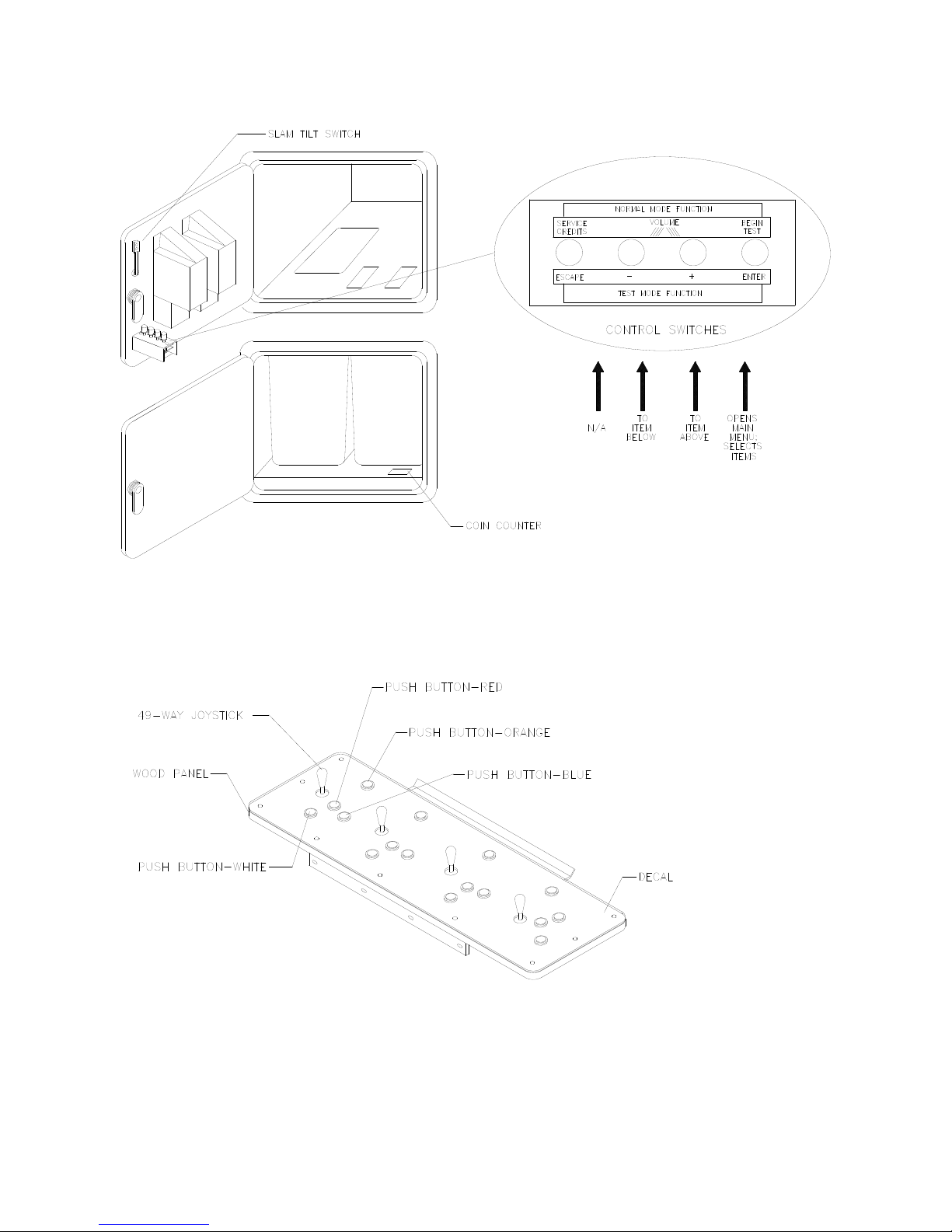
INSTALL THE CONTROL PANEL
WARNING:
The cabinet is top heavy. Use the two handles when moving the cabinet.
1. Remove all items from the shipping containers and set them aside. Inspect the exterior of the cabinet,
and control panel for damage. Pay special attention to cabinet edges, seams, and corners.
2. Remove and save the screws at the top and sides of the rear door. Unlock the rear door, then lift it off
the cabinet. Set the rear door aside. Inspect the cabinet interior for signs of damage. Check all major
assemblies to assure that they mount securely. Check the joysticks for signs of damage.
3. The coin door keys are on a key hook inside the cabinet. Unlock and open the coin door. Cash box
door and rear door keys are on a key hook attached to the rear of the coin door. Unlock and open the
cash box door. Remove the spare parts stored in the cash box.
4. Find the leg levelers and nuts in the spare parts bag. Install one nut onto each leg leveler. Hand-turn
the nut against the base of the leg leveler. Install one leveler with its nut into the threaded hole in
each corner of the cabinet. Turn the levelers all the way into the holes, but don’t tighten the levelers.
5. Unpack the player control panel. Place the player panel on the cabinet above the coin door. Open the
player panel. Align panel-mounting holes with holes in the cabinet. Install bolts with washers (two in
back; two on the bottom). Connect wiring harnesses to P1, P2, and P8 on the I-40 Joystick Interface
Board. Close the player panel. Reach up through the open coin door and lock both latches.
1-4
6. Refer to the Cabinet Wiring Diagram (Chapter 5). Check to see that cable connectors are correctly
secured. Don’t force connectors. They’re keyed to fit in only one location. Bent pins and reversed
connections may damage your game and void the warranty.
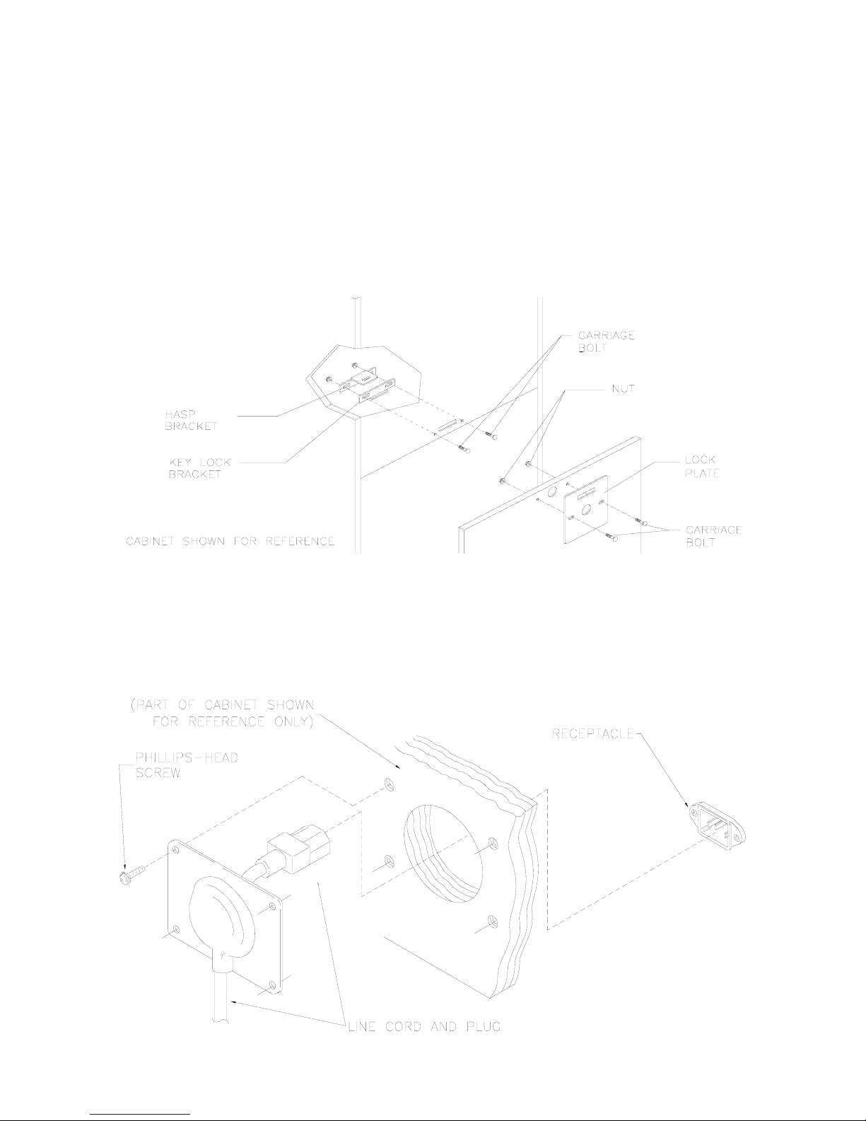
7. You can install an extra padlock to secure the rear door. You’ll find a hasp in the spare parts bag.
Remove the two lock bracket nuts from inside the cabinet, above the rear door opening. Slide the
hasp onto the bolts so that it protrudes from the hole in back of the cabinet. Reinstall nuts and tighten.
8. Modify the lock plate at the top of the rear door. Remove the bolts and nuts from the lock plate.
Rotate the plate so that the slot will be above the door. Reinstall the bolts and nuts and tighten firmly.
INSTALL THE DOOR LOCK AND SECURITY BRACKETS
9. The power cord is with the spare parts. Remove and save four screws from the line cord cover plate
at the rear of the cabinet. Match the holes on the IEC plug with the prongs in the receptacle. Push the
plug firmly to seat it. Route the cord away from cabinet wheels and foot traffic areas. Hang excess
cord on the plastic clip near the vent.
1-5
INSTALL THE LINE CORD
CAUTION: CHECK POWER SUPPLY LINE VOLTAGE SELECTOR SWITCH.
Set the
110/220 VAC selector on the power supply for the correct local line voltage. Check the
selector setting before switching on the game.
10. Reinstall the rear door and close it. Lock the rear door and remove the key. If required, install the
extra padlock through the hasp. Install the screws at the top and sides of the rear door. Tighten the
screws snugly. Close and lock the cash box and coin doors.
NOTICE:
Tamper-resistant screws and a matching wrench are provided with this game
for additional security. Four tamper-resistant screws and four wrenches are located in
the spare parts bag. If desired, replace the original screws with the tamper-resistant
screws. Tighten the screws firmly with the wrench.
11. Move the game to its play location. Lower each leg leveler until the cabinet is stable and level. Adjust
the levelers as required to raise wheels and distribute weight equally on each corner. Tighten the
nuts.
12. Plug the game into a grounded (3-terminal) AC wall outlet. Switch on the game, using the on/off
switch at the top-left rear of the cabinet. The game will power up and begin self-diagnostics. If
diagnostics find no errors, the game enters its Attract Mode of operation. Unlock and open the coin
door. Locate the control switches. Press TEST MODE to enter the Menu System.
13. Select “MONITOR SETUP” at the Diagnostics Menu. Confirm proper video display operation and
adjust the monitor as necessary.
14. Select “DISK TESTS” at the Diagnostics Menu. Run all the tests in order to verify correct drive
operation.
15. Select “SWITCH TESTS” at the Diagnostics Menu. Check to be sure that all control switches work.
16. Select “DIP-SWITCH TESTS” at the Diagnostics Menu. Verify that all switches are set to optimum
positions for this game.
17. Select “SPEAKER TEST” at the Diagnostics Menu. Verify operation of audio system components.
18. Select “EXIT” at the Main Menu. The system should enter Game-Over Mode. Open the coin door and
press the SERVICE CREDITS button to allow game play. Choose a joystick and press the START
button to begin play. Listen to the audio while playing the game. Note sound irregularities (phase
problems, no low frequencies, mono audio from stereo speakers, etc.). If necessary, check the wiring
harness for internal shorts or strapped connections.
1-6

TM
S
PORT
S
TATION
C H A P T E R
T W O
OPERATION, FEATURES,
MAINTENANCE & SERVICING
2-1

GAME OPERATION
STARTING UP
Whenever you turn on the machine or restore power, the system executes boot ROM code. The boot
ROM contains self-diagnostic tests that automatically verify and report the condition of the disk drive and
other hardware. The screen is blank during these tests. If the hardware fails a test, the system displays
an error message. The message appears for 30 seconds or until someone presses a button.
• If nobody presses a button, the system quickly completes tests, and then loads game software.
• To skip boot ROM tests and activate the Menu System, press and hold the TEST MODE button.
You’ll find this button behind the coin door.
Having passed power-up tests, the system enters Attract Mode. Attract Mode consists of typical game
scenes and sounds, alternating with high scores. Attract Mode continues until game play commences.
Players insert currency or tokens to start the game. Pressing a START determines which player receives
the credit. The game computer asks whether players want to play NBA Showtime or NFL Blitz 2000 Gold
Edition. Players request one or the other via player panel controls. Then players select a team. The game
computer associates one team with the Player-1 and Player-2 joysticks. The Player-3 and Player-4
joysticks assume control of the opposing team. Play begins after a countdown period. Play progresses
like a real-life football or basketball game. At Game Over Mode, players may choose to begin again. If
players choose not to continue, then the system returns to Attract Mode.
NFL BLITZ 2000 GOLD EDITION
INSTRUCTIONS
Play instructions appear on the information panel over and under the video monitor.
ONE TO FOUR PLAYERS
Players may enter their names for future reference. Then they select teams and run the first play. Players
may choose an offensive or defensive play. Additional game information appears on the screen as
needed. Team statistics appear at the end of each quarter.
CONTROLLING CHARACTERS
The joystick and action buttons control characters on the field. The joysticks respond to different amounts
of deflection as well as direction.
GAME ACTION
Standard league football rules apply, with two exceptions: First downs require 30 yards, and teams only
have seven active players. Game adjustment settings determine game length and speed.
The player view of the action changes automatically whenever a better camera angle becomes available.
The game sounds include announcer comments and crowd noises.
SCORING
Touchdowns and field goals score points, just as in real football games.
NFL BLITZ 2000 GOLD EDITION
STANDARD PLAYS
The player may select any of the offensive or defensive plays in the game. Players can choose from
pages of standard plays loaded into the game. Use the indicated pushbuttons to view and select any
play.
GAME RULES
PLAY SELECTION
CUSTOM PLAYS
2-2
Players may choose to create their own offensive plays rather than depend on the standard plays in the
game. Players can design and name their plays using the CREATE PLAY feature, then store these plays
for future use. These custom plays become available on an additional page of game plays.
NFL BLITZ 2000 GOLD EDITION
The player controls are used to maneuver the team members and attack or defend against adversaries.
START (orange).
•
PLAYER 2 START to begin a two-player game. START has no game action or service function.
JUMP / TACKLE.
•
tackle opponents. Use this same button to create plays or select menu items during service.
PASS / CHANGE PLAYER.
•
active control to another teammate. Use this same button to create plays or select menu items during
service.
TURBO (white).
•
Use this same button to create plays or select menu items during service.
JOYSTICK
•
time. Use the joystick to create plays or select menu items during service.
This button allows players to begin or continue play. Use PLAYER 1 START and
This button lifts the offensive team member up or causes the defensive player to
The TURBO button gives any active character an extra burst of power or speed.
. Each player has a joystick to control the movements of one on-screen character at a
PLAYER CONTROLS
This button activates offensive throws. The defense move switches
RECOMMENDED PLAYER CONTROL LOCATIONS
NBA SHOWTIME
INSTRUCTIONS
Play instructions appear on the information panel over and under the video monitor.
ONE TO FOUR PLAYERS
The player or players insert currency to start the game. Each player chooses a joystick and presses the
nearest START button. Players select a team and two characters. In four-player games, each player
controls one character. In games with fewer players, each player controls one character. The game
computer controls remaining characters. The game displays team scores and statistics at the end of each
quarter. Additional game information appears on screen as needed.
GAME RULES
2-3

CONTROLLING CHARACTERS
The joystick and action buttons control characters on the basketball court. The joysticks respond to
different amounts of deflection as well as direction.
2-4

GAME ACTION
Standard NBA basketball rules apply, except that the game only includes four active characters. Game
settings determine game length and speed. The player view of the action changes automatically
whenever a better camera angle becomes available. Game sounds include announcer comments and
crowd noises.
SCORING
The game awards points for baskets, just as in real basketball games.
NBA SHOWTIME
JOYSTICK.
•
screen.
PASS/STEAL (the blue button)
•
to attempt to pass or steal the ball.
SHOOT/BLOCK (the red button)
•
SHOOT/BLOCK to shoot or attempt to block the ball.
START (orange buttons).
•
play.
TURBO (The white button)
•
up the pace of a play.
PLAYER CONTROLS
Each player’s joystick controls the position of that player’s characters on the game
controls character actions on the game screen. Press PASS/STEAL
controls character actions on the game screen. Press
Each START button allows the corresponding player to begin or continue
controls character actions on the game screen. Press TURBO to speed
OPERATOR CONTROLS
CABINET CONTROLS
The DIP Switches
♦
switches.
The Monitor Remote Control Board
♦
The POWER Switch
♦
set some system variables. You can set other variables with diagnostic control
allows you to adjust the video display for optimum viewing.
turns off the game, but does not reset game variables.
DIAGNOSTIC CONTROL SWITCHES
The SERVICE CREDITS Button
♦
SERVICE CREDITS has no function in the menu system.
The TEST MODE Button
♦
MODE button briefly to run automatic tests. To make game adjustments, press and hold TEST
MODE until the Main Menu appears. Within the menu system, TEST MODE assumes another
function. There, it selects a menu line item and calls up the item’s submenu. The screen displays this
submenu.
VOLUME DOWN and VOLUME UP Buttons
♦
changes, press either button briefly. To make major changes, press and hold a button. In the menu
system, VOLUME UP moves the item highlight bar up the menu. VOLUME DOWN moves the item
highlight bar downward.
NOTICE:
For greater profits, increase volume levels to draw attention to this game.
causes the game to enter the service menu system. Press the TEST
You must adjust Attract Mode volume independently of Game Mode volume.
allots credits without changing the game's bookkeeping total.
set game sound levels. To make minor volume
2-5

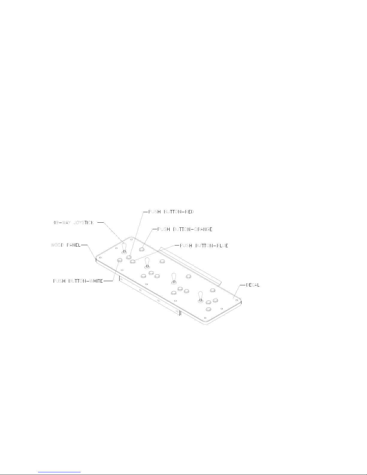
PLAYER CONTROLS
2-6
DIAGNOSTIC CONTROL SWITCH LOCATIONS
PLAYER CONTROL LOCATIONS
2-7

MAINTENANCE
♦
Cabinet
Use only non-abrasive cleaners to avoid damaging game graphics. Apply cleaner to a clean cloth or
sponge. Wipe the screen clean with this cloth or sponge. Do not apply cleaner directly on the cabinet!
♦
Control Panel
Dirt or debris on the joysticks or buttons can affect earnings. Apply the cleaner to a clean cloth. Use
the cloth to wipe the controls. Don’t apply the cleaner directly to the controls!
♦
Viewing Glass
To clean the glass, you don’t need to switch off power to the game. Apply a mild glass cleaner to a
clean cloth or sponge. Use this to wipe the viewing glass. Do not apply the cleaner directly on the
glass! Liquid could drip down into switch or motor circuits and cause erratic game operation.
SERVICING
Only qualified service personnel should perform maintenance and repairs. The following product
guidelines apply to all game operators and service personnel. Notes, cautions and warnings appear
throughout this manual where they apply. Read the SAFETY pages thoroughly before beginning service.
♦
Circuit Board Set
The SportStation game computer uses a set of three circuit boards. The three boards include the
CPU Board, I/O Board and Video Board. Switch off power to the game. Open the rear door. To
expose the circuit boards, remove their perforated metal cover. Carefully note the orientation of the
JAMMA connector and other cables. Extract the harness and hard disk drive ribbon cable from the
board connectors. Remove circuit board mounting screws. Lift the circuit boards out of the cabinet
and set them in a safe place. Use anti-static packaging from new parts to store boards that you won’t
reinstall.
CAUTION:
boards in the board set. Never jam the board connectors together. Never plug them
together on an extreme angle. If necessary, carefully straighten bent pins with a
small, grounded flat blade screwdriver. Also, don’t touch exposed foil on printed
circuit boards. Skin oils are corrosive.
NOTICE:
circuit boards or any electronic assembly. Never “hot plug” circuit boards.
♦
Coin Mechanism
Switch off power to the game. Unlock the coin door and swing it open. To clean or replace a coin
mechanism, unlatch and remove it. After reinstallation, ensure that the mechanism seats fully its
bracket. Close and lock the release latch, and then close the door. Turn on the game and change the
mechanism setup. Test known good and bad coins to verify operation.
♦
Coin Meter
Switch off power to the game. Unlock the cash door and swing it open. The coin meter mounts to a
metal plate at the bottom the cash vault. Record the meter count before testing or replacement.
Remove the plate’s four mounting screws, and then remove the plate.
Circuit board edge connectors are fragile. Take care when separating
Avoid damage to game electronics! Turn off game power before servicing
2-8

Disconnect the meter wiring harness at the connectors. Remove front screws and slide the meter out.
Assure that a protective diode connects across the replacement meter’s terminals. The diode
prevents driver circuit damage.
2-9

REINSTALLING CIRCUIT BOARD ASSEMBLIES
2-10
♦
Hard Disk Drive
Switch off power to the game. Unlock and remove the rear cabinet door. Remove the perforated
metal cover over the game electronics. Disconnect the DC power cable from the hard disk drive.
Unplug the ribbon cable from the hard drive. Don’t disconnect the cables from the CPU Board.
Loosen the drive mounting screws and lift the drive out of its mounting bracket. Remove the screws.
Save them for reuse in future hard drive installations. When returning a hard drive to your distributor,
pack it in an anti-static bag. Box the drive in approved shipping container 08-8068.
NOTICE:
or drop hard disk drives. Keep disk drives away from magnets, heat and vibration.
♦
Joysticks
Switch off power to the game. Open the player control panel. Mark and disconnect the wiring harness
from a joystick. To separate the joystick from the player panel, first remove the joystick shaft. An Ering secures the shaft. Disengage this E-ring with a small, flatblade screwdriver. Grasp the joystick
knob. Extract the stick from the assembly. Then remove 8-32 tamper-resistant (KEPS®) nuts from the
corners of the joystick base. Retain fasteners for reassembly.
Hard disk drives are very fragile! Handle them with care. Do not stack
2-11
♦
Memory
CAUTION:
destroy sensitive the game circuits. BEFORE touching or handling electronic
assemblies, discharge static electricity by touching the electronics mounting plate.
NOTICE:
mounting chips on either board, refer only to chips on the same board for
reference. Never use the chips on another board for reference.
ROM (Read Only Memory) circuits contain computer operating instructions for this game. Switch off
power to the game. Unlock and remove the rear door. Remove the perforated metal cover. Note the
ROM chip position. Remove the device with a chip extraction tool. To reinstall a ROM chip, orient the
device over its socket. Press the chip firmly to seat pins. Don’t force the chip into the socket.
Static electricity builds up on your body. This static can damage or
CPU Board and SI/O Board chips don’t face same direction. When
CABINET FRONT VIEW
EXTERNAL COMPONENTS
2-12

GAME ELECTRONICS
♦
Monitor Bezel
Switch off power to the game. Open the control panel. Remove the viewing glass. Lift the bezel up
and off the monitor. Set the bezel aside. Clean the labels. Orient the labels right side up, so that
players can read them. Reinstall the bezel.
♦
Viewing Glass
Switch off power to the game. Open the control panel. Loosen three mounting screws. Slide the black
metal strip from the bottom of the glass. Carefully slide the glass from the side grooves. Then lift it
clear of the cabinet. Set the glass in a safe place. Clean the glass before reinstalling it.
♦
Monitor
CAUTION:
the assembly. Support the monitor as you remove it from the cabinet.
INTERNAL COMPONENTS
The video monitor is heavy, with most of the weight toward the front of
2-13

WARNING:
normal game operation. When operating the monitor outside the cabinet, use an
isolation transformer. Connect the transformer between the monitor and line.
Switch off power to the game. Open the control panel. Remove the viewing glass and monitor bezel.
Unlock and remove the rear door. Disconnect the monitor from the wiring harness, remote
adjustment board, and ground wires. Remove the fasteners that secure the monitor frame to its
mounting panel. Carefully pull the monitor from the cabinet. Set the monitor in a safe place. Remove
the remote adjustment board from the cabinet and reconnect it to the monitor before servicing or
replacement. Clean the face of the monitor before reinstalling the monitor bezel.
♦
Power Supply
Switch off power to the game. Unlock and remove the rear door. Remove the electronics rack and set
it aside. Unplug the IEC AC connector from the rear of the supply. Unplug the power wiring
harnesses from the back of the supply. Remove two front and two rear screws from the supply. Lift
the supply off the power chassis. Slide the supply out of the cabinet.
The monitor doesn’t require isolation from AC line voltage during
Reinstallation.
voltage switch to the correct value. Place the supply on the power chassis. Align the chassis
mounting holes. Install the four screws and two power connectors. Connect the IEC AC connector to
the rear of the supply. Replace the electronics rack. Plug the power wiring harnesses into the back of
the supply. Replace and lock the rear door. Switch on power to the game.
♦
Speakers
Switch off power to the game. The full-range speakers are mounted behind grilles at the top of the
player panel. Grilles and speakers come out from the front. Remove the screws and set the grilles
aside. To avoid damaging a speaker, remove upper mounting screws first, and replace them last.
Remove the speakers from the enclosure just enough to expose the terminals. Label and disconnect
the wires. Refer to the Wiring Diagram (Chapter Five) for speaker wiring information. Don’t use
excess force when removing or tightening screws threaded into plastic or particle board.
Verify the line voltage switch setting before reinstalling the power supply. Set the
2-14
TM
S
PORT
S
TATION
C H A P T E R
T H R E E
DIAGNOSTIC, AUDIT &
ADJUSTMENT MENU SYSTEM
FOR NFL BLITZ 2000 GOLD EDITION GAMES
NOTICE:
right to make improvements in equipment as progress in engineering warrants.
NOTICE: GAME-SELECTION SWITCH.
switch 8 at DIP bank U13. Then power down and up again. The Attract Mode for the
game you select will appear. The player can still play either game.
Information in this manual is subject to change without notice. Midway reserves the
Select NBA Showtime or NFL Blitz by flipping
3-1

MENU SYSTEM
WHAT IS THE MENU SYSTEM?
The game’s Menu System is a series of auditing, game adjustment and diagnostic screens. You can
easily access and apply these screens to optimize game performance. For instance…
• Use game audits screens to assess game performance.
• Use adjustment screens to help you to customize game performance. For instance, you can restore
factory default game settings. You can also calibrate player controls for accuracy.
• Use diagnostic screens to verify proper equipment operation.
ACTIVATING THE MENU SYSTEM
Open the coin door. Find the TEST MODE switch inside. Press TEST MODE to invoke the Menu System.
The game system responds by exiting Game Mode and entering Diagnostic Mode.
AUTOMATIC TESTS
In Diagnostic Mode, the Power-On Self-Test (POST) activates. This routine runs automatically. It can
detect faults that cause game or Menu System malfunctions. POST usually takes less than a minute. The
test doesn’t display anything. Instead, the system boot loader indicates the software revision number and
serial numbers. The system boot loader also displays a sound-loading message and other useful
information.
At the end of POST, the system displays the Control Functions Menu.
CONTROL FUNCTIONS MENU
The Control Functions Menu is purely informational. It appears for five seconds. Then the Menu System
automatically displays the Dual Game Adjustment Menu.
The Control Functions Menu introduces the menu navigation controls. The key point is that you can use
either player or diagnostic controls to navigate menus. Diagnostic control switches are particularly helpful
when you must troubleshoot player switches. This manual discusses the controls in more detail in this
chapter’s Main Menu section. Also see the page on the menu that interests you.
STICK UP/VOLUME UP – MOVE UP
STICK DOWN/VOLUME DOWN – MOVE DOWN
STICK RIGHT – MOVE RIGHT
STICK LEFT – MOVE LEFT
PUSH BUTTON/TEST BUTTON - SELECT
5 SECONDS TO DIAG ENTRY
CONTROL FUNCTIONS MENU
3-2

DUAL GAME ADJUSTMENT MENU
The Dual Game Adjustment Menu is another informational, read-only menu. It appears until you choose
to exit. This menu reminds you that some NFL settings also affect NBA game play. Press any button to
exit to the Main Menu.
ATTENTION!
ANY CHANGES TO THE FOLLOWING ADJUSTMENTS
UPDATE BOTH NBA AND NFL
PRICING
FREE PLAY
VOLUME LEVEL
DISCOUNT PRICE / CREDITS
ATTRACT MODE SOUND ON / OFF
THIS ALSO INCLUDES DEFAULT ADJUSTMENTS
AND
FULL FACTORY RESTORE FUNCTIONS.
PRESS ANY BUTTON TO EXIT.
DUAL GAME ADJUSTMENT MENU
MAIN MENU
The Main Menu offers you access to the game machine’s test, bookkeeping and programmable features.
Game audits, adjustments and diagnostics are line items on the Main Menu. Selecting an item opens its
submenu. Every submenu presents various options that you
may act upon.
NFL MAIN MENU
DIAGNOSTICS
AUDITS
ADJUSTMENTS
VOLUME LEVEL
UTILITIES
NBA MAIN MENU
EXIT TO NBA
EXIT TO NFL
MAIN MENU
MENU LAYOUT
Menus differ, but related information tends to occupy the same screen locations.
• The block at the top, center of each screen displays the current menu title.
• Data (menu items, video signals, statistics, reports, etc.) appears in the center of the screen.
• Messages (explanations, control functions, revision levels) display at the bottom of the screen.
MENU NAVIGATION CONTROLS
Use any player panel joystick to highlight a desired menu item. You can only select one highlighted item
at a time. To select a highlighted item, press any player panel button. Operator control buttons inside the
coin door serve as backup menu navigation controls. Press VOLUME UP or VOLUME DOWN buttons to
highlight a menu item. Press TEST MODE to select a highlighted item.
EXIT OPTIONS
To exit the NFL menus and simultaneously enter the NBA menus, choose NBA MAIN MENU. To return
the game to play, highlight either EXIT TO NFL or EXIT TO NBA. Your choice determines the game that
will boot. Next, press any button.
3-3

Main Menu (continued)
Diagnostics Menu
DIAGNOSTICS
Select DIAGNOSTICS at the Main Menu. Diagnostic tests allow you to verify the condition of the electrical
and electronic hardware in the game.
Highlight a test with any player panel joystick. Select the option with any player panel button.
DIAGNOSTICS
MONITOR SETUP
SYSTEM INFO
SOUND SUBSYSTEM
DISK TESTS
SWITCH TESTS
DIP-SWITCH TESTS
SPEAKER TEST
EXIT
DIAGNOSTICS MENU
Diagnostic tests assist you in checking and adjusting the game’s major systems. By running diagnostics,
you can gain an insight into both system hardware and game software. Periodically running diagnostics is
a crucial part of maintaining game performance and player satisfaction. Sometimes you can improve
game performance by running a diagnostic test and making appropriate adjustments.
3-4

Main Menu (continued)
Diagnostics Menu (continued)
Monitor Setup Menu
MONITOR SETUP
Select MONITOR SETUP at the Diagnostics Menu. The Monitor Patterns routine provides test screens to
verify monitor performance or make adjustments.
Highlight an option with any player panel joystick. Select the option with any player panel button.
MONITOR SETUP
COLOR BARS
CROSSHATCH
RED SCREEN
BLUE SCREEN
GREEN SCREEN
WHITE SCREEN
BLACK SCREEN
50 PCT. GRAY SCREEN
25 PCT. GRAY SCREEN
EXIT
MONITOR SETUP MENU
Color Bars
fills the screen with colored stripes. Use the color bars to help you to check or adjust monitor
brightness and contrast. The color bars also expose defects in horizontal linearity. Each color bar consists
of 32 intensity levels. On a properly adjusted monitor, the top 31 of these levels are visible. Each bar
should appear sharp, clear and distinct from bars on either side. Incorrect adjustment can cause missing
detail at the top or bottom of a bar. Bent bars indicate horizontal linearity flaws, such as pie crust,
pincushion or barrel distortion. (Correct color bar colors, left to right: Red, Green, Blue, Black, White,
Cyan, Yellow, Violet.) Set controls as follows: 1. Adjust BRIGHTNESS and CONTRAST to minimum. 2.
Turn up BRIGHTNESS until the pixels in the black stripe begin to glow (turn dark gray). 3. Bring up the
CONTRAST control until you can see 31 bars.
Crosshatch Patterns
fill the screen with a grid and a series of dots. Crosshatch Patterns help you to
check or adjust several monitor parameters: These include convergence, linearity, active viewing area
and dynamic focus. The grid and the dots should be all white in color, with no fringes or parallel images.
The lines should be straight and the dots round. For more detail on these adjustments, consult service
literature from the monitor manufacturer.
Color Screen
tests fill the screen with 100% of the chosen color at normal intensity. The Color Screen
tests help you to check or adjust monitor intensity, black level, blanking and color purity. Each screen
should be absolutely uniform from top to bottom and side to side. No retrace lines or noise should be
visible. Color Screens may not hold their uniformity if the monitor degaussing circuit is defective.
White, Gray and Black Screens
fill the screen with black, gray or white at various intensities. These
monochrome screens help you to check or adjust monitor convergence, purity, contrast and intensity.
These screens also simplify black level and color gun control settings. The screens should be uniform
with no color tints or distortion. No retrace lines or noise should be visible.
If tests indicate a need for adjustment, use controls on the Monitor Remote Adjustment Board.
3-5

Main Menu (continued)
Diagnostics Menu (continued)
System Information Menu
SYSTEM INFORMATION
Select SYSTEM INFO at the Diagnostics Menu. The System Information Menu provides the current
version numbers of this game’s hardware and software. Use these numbers to describe the system
during parts replacement, service calls, etc.
Highlight an option with any player panel joystick. Select the option with any player panel button.
SYSTEM INFORMATION
MIDWAY GAMES, INC.
XXXXXXX SYSTEM
SERIAL NUMBER: XXXXXXXXX
GAME: XXXXXXXXXX
DATE OF MANUFACTURE: XX/XX/XX
PRESS ANY BUTTON TO EXIT
SYSTEM INFORMATION MENU
The System Information screen reports information, but doesn’t permit you to make changes. The Title
line identifies the manufacturer of this game and the electronic board set used in this product. The Serial
Number, Game and Date of Manufacture identify the game name and production run.
3-6

Main Menu (continued)
Diagnostics Menu (continued)
Sound Subsystem Menu
SOUND SUBSYSTEM TEST
Select SOUND SUBSYSTEM at the Diagnostics Menu. Sound Subsystem Tests verify that audio
components are connected and operate properly.
Highlight an option with any player panel joystick. Select the option with any player panel button.
SOUND SUBSYSTEM TEST
BOOT VERSION: XX.XX
SDRC VERSION: XX.XX
PORT STATUS: GOOD
CHECKSUM: XXXX
SRAM: OK
DRAM: OK
TONE STATUS: GOOD
OS VERSION: XX.XX
PRESS ANY BUTTON TO EXIT
SOUND SUBSYSTEM MENU
Version, Status, Checksum and RAM Reports
are diagnostic routines. These routines analyze the
digital sound circuits and can detect sound memory problems. Test results appear as numbers or
messages. Sounds may also accompany some tests. Reports other than GOOD or OK indicate a
problem.
3-7

Main Menu (continued)
Diagnostics Menu (continued)
Disk Tests Menu
DISK TESTS
Select DISK TESTS at the Diagnostics Menu. Disk Tests allow you to verify proper operation of the hard
disk drive assembly.
Highlight an option with any player panel joystick. Select the option with any player panel button.
DISK TESTS
DISK INFORMATION
SEQUENTIAL READ
SEQUENTIAL CACHE READ
RANDOM READ
RANDOM CACHE READ
DATA INTEGRITY TEST
FILE SYSTEM CHECK
SURFACE SCAN
EXIT
DISK TESTS MENU
Disk Information.
The Disk Information routine verifies the interface between the CPU Board Assembly
and hard disk drive. The processor requests disk information. Data cannot be retrieved successfully if
there is a problem.
Sequential Disk Read.
This routine tries to access every bit of data in the order it is stored directly on the
disk. The hard disk drive media may be defective if this routine cannot be completed successfully.
Sequential Cache Read.
This routine tries to access every bit of data in the order it is stored in the
temporary disk memory cache. If this test is not successful, the memory circuits may be faulty.
Random Disk Read.
This routine tries to access every bit of data in no particular order directly from the
disk. This test may detect problems with ability to position the drive heads accurately over the requested
data.
Random Cache Read.
This routine tries to access every bit of data in no particular order from the
temporary disk memory cache. If the cache fails this test, memory circuits may contain a fault.
Data Integrity Test.
This test analyzes the data on the disk drive. The test determines if corrupted data is
on the disk. Bad data can cause the program to falter even though the hard disk operates correctly.
File System Check.
Surface Scan.
This routine performs a file-by-file check of the data stored on the hard disk.
The magnetic material on the disk can become damaged, causing data to be unreadable.
This routine locates unusable areas on the disk and marks them for future reference.
3-8
 Loading...