

Midway Skins Game Operation Manual

FEBRUARY 2000
16-30042-101
675 Sycamore Dr. Milpitas, CA 95035 USA
Operations Manual Includes
Setup z Service z System
Wiring z Parts z Troubleshooting
Midway Games West Inc.
http://www.midway.com
UPRIGHT
DEDICATED
VIDEO GAME
25” CABINET
86
/,67('
CHAPTER
SAFETY AND SETUP
NOTICE:
the right to make improvements in equipment function, design, or components as progress in
engineering or manufacturing methods may warrant.
Fill out and mail in the Game Information Card. Include the serial number from the label on the
rear of the cabinet. For your records, write the serial number in the manual.
SERIAL NUMBER _______________________________________________________
This manual is subject to change without notice. Midway Games West Inc. reserves
SAFETY INSTRUCTIONS
The following safety instructions apply to operators and service personnel. Read these instruc tions before
preparing the game for play. Other safety instructions appear throughout this manual.
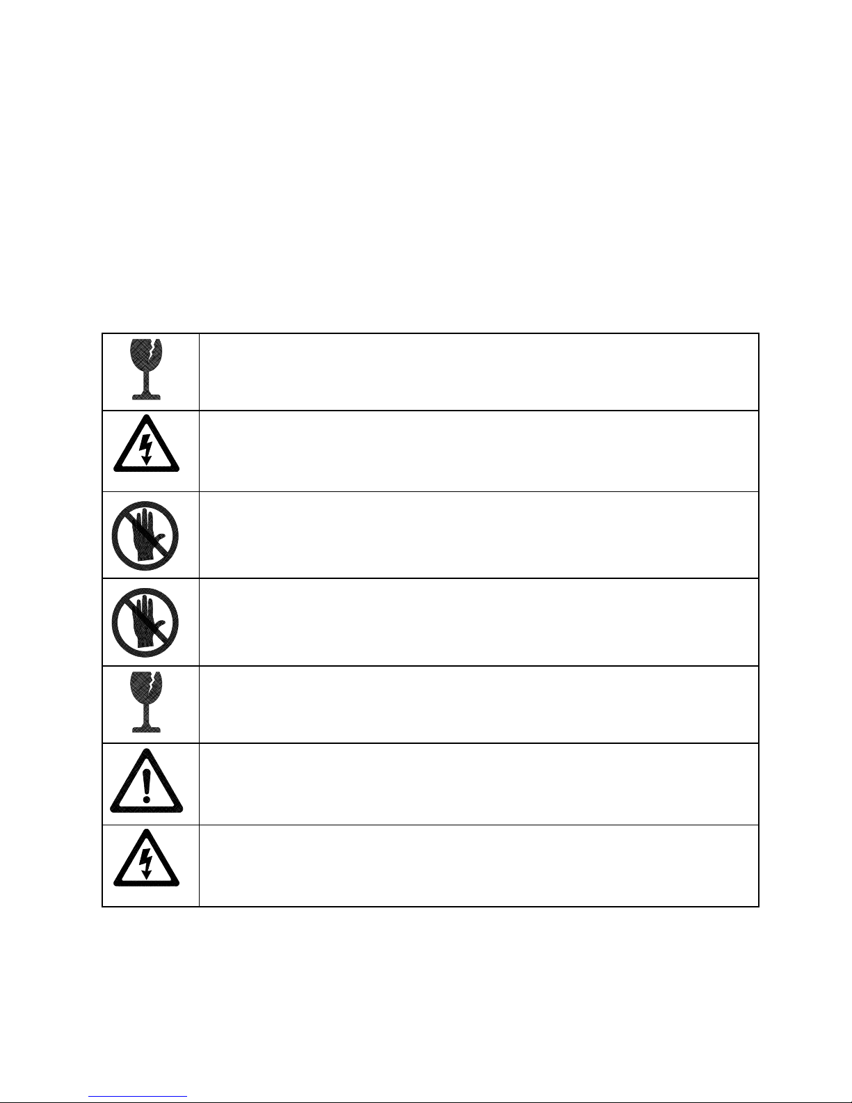
DEFINITIONS OF SAFETY TERMS
DANGER
injury.
indicates an imminent hazard. If you fail to avoid this hazard, it WILL cause death or s erious
WARNING
injury.
CAUTION
injury. CAUTION also alerts you about unsafe practices.
NOTICE
indicates a potential hazard. If you fail to avoid this hazard, it COULD cause death or serious
indicates a potential hazard. If you fail to avoid this hazard, it MAY cause m inor or moderate
indicates information of special importance.
WARNING: TRANSPORTING GAMES
devices. Use appropriate care when transporting this game. Avoid r ough handling when
moving the cabinet. Do not move this game with AC power ON.
WARNING: DISCONNECT POWER
before attempting service or adjustments unless otherwise instructed. Installing or
repairing PC boards with power ON can damage components and void the warranty.
WARNING: GROUND GAMES
have inspected and properly grounded it. Only plug this game into a grounded, threewire outlet. Do not use a “cheater” plug, or cut off the ground pin on the line cord.
WARNING: AVOID ELECTRICAL SHOCKS
an isolation transformer. Internal cabinet AC is not isolated from the external AC line.
. Avoid electrical shocks ! Do not plug in a gam e until you
This game contains glass and fragile elec tronic
Always turn AC power OFF and unplug the gam e
. This video game system does not utilize
WARNING: HANDLE FLUORESCENT TUBE AND CRT WITH CARE.
fluorescent tube or CRT and it break s, it will implode! Shatter ed glass can fly eight feet
or more from the implosion.
CAUTION: CHECK POWER SELECTOR, LAMP.
power supply for the correct line voltage. Check the selector setting before switching on
the game. Verify that the fluorescent lamp assembly is correct for the local line voltage.
CAUTION: USE PROPER FUSE.
the same type as those they replace. Fuse voltage and current ratings must match
ratings on the original fuse.
Setup - 2 Midway Games West Inc.
If you drop a
Set the 115/230VAC selector on the
Avoid electrical shock! Replac ement f uses m ust be of
CAUTION: ATTACH CONNECTORS PROPERLY.
(PCB) connectors mate properly. If connectors do not slip on easily, do not force them. A
reversed connector m ay damage your game and void the warranty. Connector k eys only
allow a connector to fit one set of pins on a board.
Be sure that printed circuit board
W
elcome to Skins Game!
CAUTION: USE CARE WHEN SHIPPING HARD DISKS.
packed in an anti-static bag. When shipping the drive for repair or replacement, pack it in
an approved container (P/N 08-8068). Do not stack or drop hard disk drives. Moving
cabinet while AC power is on can also damage hard drive.
WARNING: HAZARD TO EPILEPTICS.
condition which may cause them to experience epileptic seizures or have momentary
loss of consciousness when viewing certain k inds of flashing lights or patterns that are
present in our daily environment. These persons may experience seizures while
watching some kinds of television pictures or playing certain video games. People who
have not had any previous seizures may nonetheless have an undetected epileptic
condition.
If you or anyone in your family has experienced symptoms linked to an epileptic condition
(e.g., seizures or loss of awareness) , immediately consult your physician before using
any video games.
We rec ommend that parents obser ve their children while they play video games. If you
or your child experience the following symptoms: dizziness, altered vision, eye or muscle
twitching, involuntary movements, loss of awareness, disorientation, or convulsions,
DISCONTINUE USE IMMEDIATELY and consult your physician.
A very small portion of the population has a
The hard disk drive m ust be
It’s a beautiful day on the digital fairway. Midway Games West Inc. keeps the greens perpetually
immaculate. In Skins Game, you and up to three other players are invited to practice your putting, perfect
your drive, or simply haul off and lob a bucket of balls into the water hazards. Don’t worry. We’ll refill the
bucket.
Ultra-realistic Skins Game is just like a round of golf, minus the strenuous exercise. Your Midway caddy
warns you about sand traps and water hazards and offers the best route for your shots. She selects what
she thinks is the best club, but you may choose yourself from a full bag of putters, drivers, wedges, and
irons—all custom crafted for optimal performance. As you enjoy your game, birds chirp peacefully in the
distance and the sun shines with nary a cloud to speak of. Heatstroke is never a problem.
Adjust your stance and shot direction all you like, but your virtual player begins each stroke oriented in the
best stance and direction to hit the pin. While the three-dimensional terrain forces your ball to follow
Newtonian physics, your shot “snaps” to the pin unless you choose to aim elsewhere. And a peek at the
wind gauge may convince you to do so! The wind will send your ball off course if you’re not careful.
Of course in Extreme Mode, say bye-bye to Mr. Newton as you change the ball’s path or spin in mid-flight.
Players who don’t dawdle at the tee earn QuickShot bonuses, rewards for hitting the ball within 15
seconds. Collecting 10 QuickShot bonuses gives you an extra Power Shot. And Power Shots mean added
distance with your clubs. However, you must carefully time the joystick release, or your Power Shot
becomes a nasty hook or slice. Normally, players earn one Power Shot for each three holes.
As your game improves (or not), a hard drive records your scores. With the keypad, you can enter a PIN
that identifies you and calls up your statistics–in case there was any doubt about your birdie on the fourth
hole at Eagle Ridge.
Skins Game Setup - 3
PRODUCT SPECIFICAT IONS
Operating Requirements
Location
Domestic
Foreign
Japan
Cabinet Statistics
Shipping Dimensions
Height 73" (185 cm)
Width 28" (71 cm)
Depth 42" (106 cm)
Equipment Characteristics
Video Display Monitor
Standard Resolution (15.7 KHz) RGB
25” (64 cm) CRT
Game Characteristics
Player Variables
1 to 4 players per game (with Linking)
Choice of Character
Character Profile Memory
Electrical Power
120VAC @ 60Hz 3.0 Amps
230VAC @ 50Hz 2.0 Amps
100VAC @ 50/60Hz 3.0 Amps
Temperature
37°F to 100°F
(3°C to 38°C)
Shipping Weight
400 lbs. (148.2 kg.)
Audio System
2 Channel Audio
2 Full Range Speakers
Operator Variables
Coinage, Play Mode,
Difficulty, Volume,
Audits, Statistics
Humidity
Not to exceed 95% relative
Design Type
Single Dedicated Video
Game with Linking capability
Currency Acceptors
Standard Coin Door
2 Coin Mechanisms, DBV ready
1 Coin Counter
Diagnostics
Automatic Power-Up Test
Manual Multi-Level Menu System
PRODUCT CONFIGURAT ION
Stand Alone Units
•
Each game is ready to play right out of the box. Operators may use the screens in the Menu System
to determine some player variables in advance or leave the choices up to the players.
MAINTE NANCE
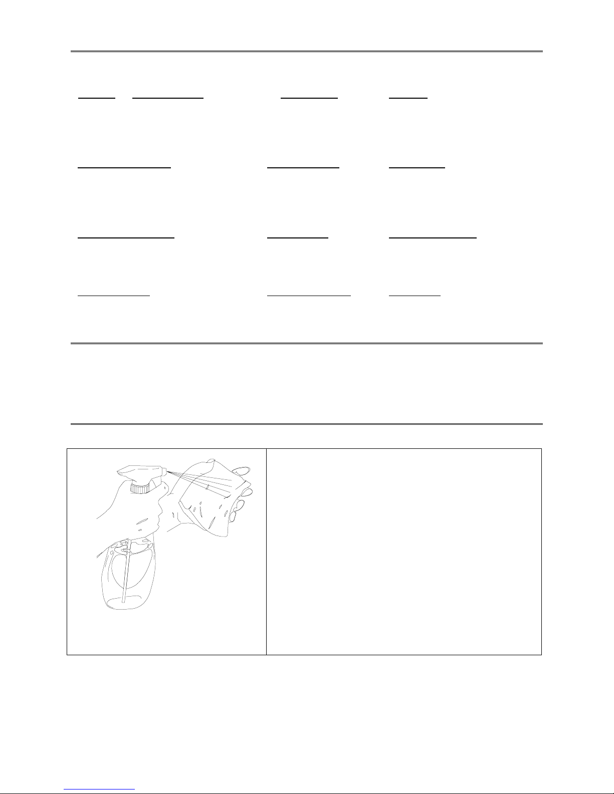
Viewing Glass
•
It is not necessary to switch off AC power to clean
glass. Apply a mild glass cleaner to a clean cloth or
sponge. Use this to wipe viewing glass. Do not apply
cleaner directly on glass! Liquid could drip onto switch
or control circuits and cause erratic game operation.
Player Controls
•
Use plastic-safe non-abrasive cleaners. Apply cleaner
to a clean cloth or sponge. Use this to wipe player
controls. Do not apply cleaner directly on controls!
Cabinet
•
•
Use plastic-safe non-abrasive cleaners to avoid
damage. Apply cleaner to a clean cloth or sponge. Use
this to wipe seat or cabinet. Do not apply cleaner
directly on artwork or cabinet!
Setup - 4 Midway Games West Inc.
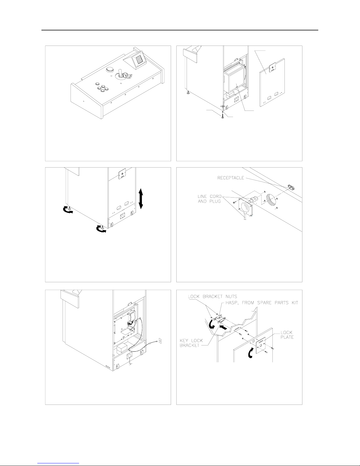
HARDWARE SETUP
12
LEVELER
NUT
Remove items from shipping container. Inspect cabinet
exterior for damage.
Remove coin door key from joystick. Unlock and open
coin door. Locate rear door and coin vault keys on key
hook behind coin door. Locate electrical cords and
spare parts in cash tub in coin vault.
Unlock, remove and set aside rear door. Remove
groundplane cover. Ensure major assemblies and cable
connectors are mounted securely and fan airflow is
unobstructed. Do not force connectors. Tilt cabinet to
locate four threaded holes on bottom. Install leveler and
nut into each hole, but do not tighten yet.
REAR DOOR
GROUNDPLANE
COVER
43
Stand cabinet upright and make certain it is in a stable
position. Move game to its intended location and level
the cabinet. Game is intended for use only in a fixed
position. Ensure that final adjustment raises game so
swivel caster wheels do not touch the floor. Distribute
weight equally on each corner and tighten leveler nuts.
Remove and save four screws from line cord cover plate
at cabinet rear. Remove cover plate. Match holes on IEC
plug with prongs in receptacle and push firmly to seat
line cord. Hold cord flat against cabinet and reinstall
cover plate (indentation points down so cord exits
toward bottom of cabinet).
56
To install your own padlock to further secure rear door,
remove lock bracket nuts from inside cabinet, above rear
Uncoil telephone cable inside cabinet. Run cable
through notch in cabinet rear and plug into working
telephone jack. Replace groundplane cover, taking care
not to pinch wires or cables. Replace and lock rear door.
door opening. Reverse hasp so it protrudes from hole in
back of cabinet. Reinstall nuts. Remove nuts from rear
door and flip metal plate so hole extends above top of
door. Reinstall nuts and door.
Skins Game Setup - 5
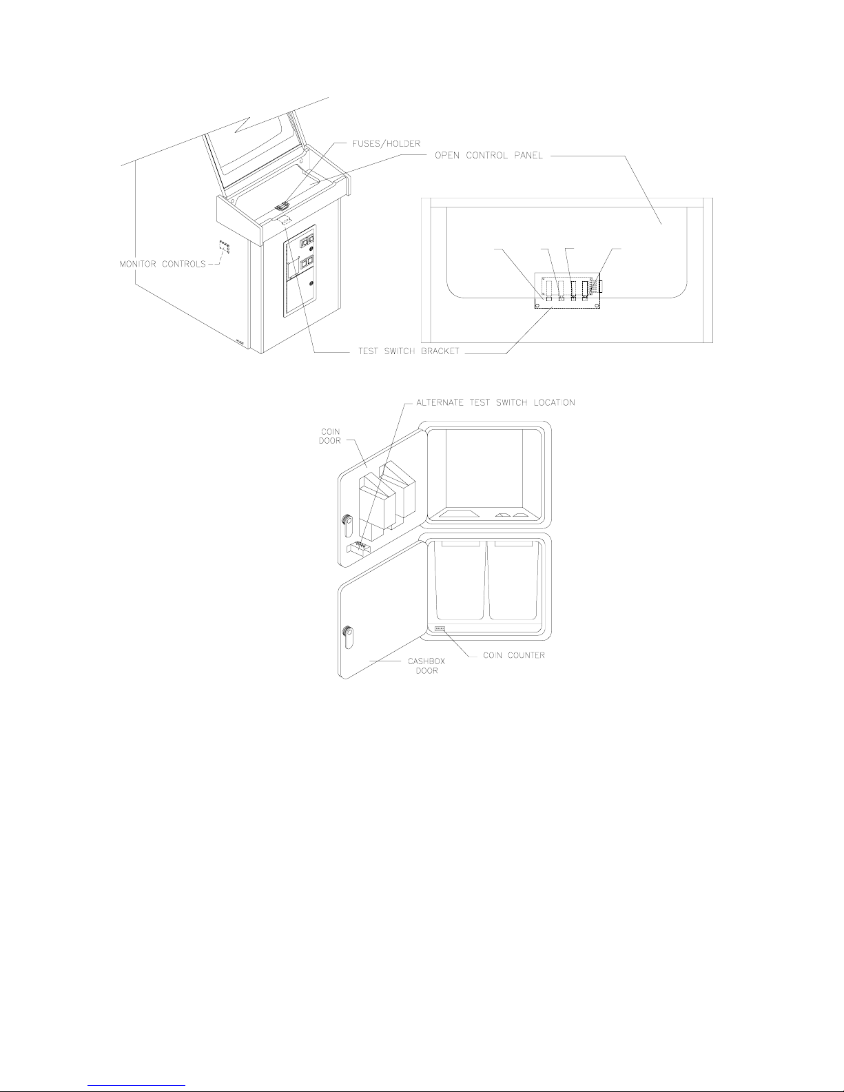
SOFTWARE SET UP
TEST
MODE
VOL.
UP
TOP VIEW
VOL.
DOWN
SERVICE
CREDIT
Note: If battery-backed up RAM is reinitialized (as when power is turned on for the very first time) you will
see a Calibrate Pot screen with an explanation of how to calibrate.
1. Unlock and open cash door. Press TEST MODE pushbutton on operator control switch panel to enter
Menu System. See System Chapter in this manual for more information on system software.
2. When Main Menu appears, follow on-screen instructions to select ADJUST VOLUME. Set game and
Attract Mode volume to desired levels.
3. Return to Main Menu and choose TESTS. Then select CONTROLS TEST. Follow on-screen
instructions to verify that controls are operational. If no errors are found, controls should function well.
4. Return to Main Menu and select SET DATE/TIME. Follow on-screen instructions to verify correct time
for your city.
5. Return to Main Menu screen, then choose EXIT TO GAME. Skins Game automatically enters Attract
Mode.
6. Insert currency or tokens and play a game. Change the volume with the pushbuttons behind cash
door and make any other desired adjustments.
7. Close and lock cash door
Setup - 6 Midway Games West Inc.

CHAPTER
SERVICE
NOTICE:
the right to make improvements in equipment function, design, or components as progress in
engineering or manufacturing methods may warrant.
This manual is subject to change without notice. Midway Games West Inc. reserves
SERVICE
CAUTION:
Game Machine, turn AC Power off. Failure to do so can cause personal injury, may
damage the components, and may void your warranty.
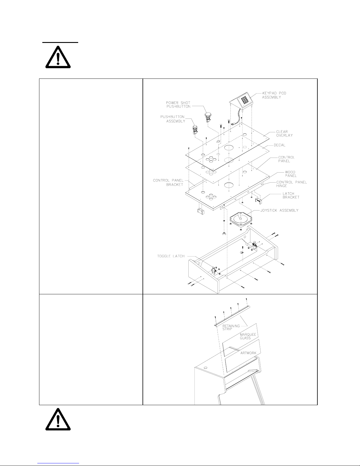
Control Panel
To open control panel, open coin
door and reach upward, feeling for
left and right latches (see illus tr ation).
Latches hold control panel top to
control panel box. Unlock latches and
swivel top of hinged control panel
toward you by pulling upward gently
on keypad pod assembly.
To remove control panel assembly,
open control panel. Mark, and
disconnect wiring harnesses from
player controls. Use a wrench to
remove four ¼-20 hex-head bolts,
flat washers, and lock washers that
secure control panel to cabinet.
Close control panel cover. Slide
control panel housing away from
cabinet.
To reinstall, align gasketed control
panel bracket with bottom of viewing
glass. Tighten mounting bolts firmly,
but do not overtighten.
Before attempting any of the following procedures on your Skins Game Video
Marquee
Remove five hex-head wood screws
that hold marquee-retaining strip to
cabinet top. Hold glass in place to
avoid breakage. Remove retaining
strip and set aside. Lift marquee
glass out of top grooves and set in
safe place. Do not overtighten
screws during reinstallation.
WARNING:
removed. Hold glass in place until you can safely remove it.
Service - 2 Midway Games West Inc.
Marquee glass can fall from cabinet and break when retaining strip is
WARNING:
A dropped fluorescent tube is likely to break, implode, and shatter glass
eight feet or more from the point of destruction. Use extreme care when handling.
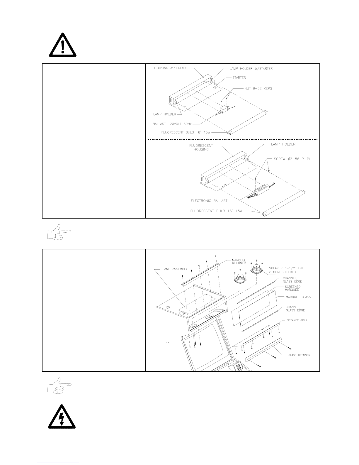
Fluorescent Lamp
Remove marquee housing, retaining
strip, glass, and artwork. Grasp bulb,
and rotate a quarter turn. Pull tube
from sockets.
To replace, carefully fit new bulb into
socket and rotate a quarter turn.
Clean bulb to remove fingerprints
and dust.
Fluorescent Light Assembly
Remove marquee housing, retaining
strip, glass, and artwork. Disconnect
power cable from fluorescent light
assembly. Loosen screws fastening
assembly to cabinet, but do not
remove them. Slide assem bly slightly
forward to disengage keyhole slots.
Lift assembly out of cabinet.
NOTE:
Fluorescent light assemblies with electronic ballasts have no starter.
Speakers
Remove marquee, glass, and
artwork. Label and disconnect wires.
Remove nuts on screws. Lift
speakers up above speak er grill and
out of marquee. Carefully reseat
seals upon completing any task in
speaker enclosure. Refer to Cabinet
Wiring Diagram for correct speaker
polarity.
NOTE:
Ensure replacement speakers are magnetically shielded. This prevents video
monitor color impurity.
CAUTION: USE PROPER FUSE.
the same type as those they replace. Fuse voltage and current ratings must match
ratings on the original fuse.
Skins Game Service - 3
Avoid electrical shock! Replacement fuses must be of
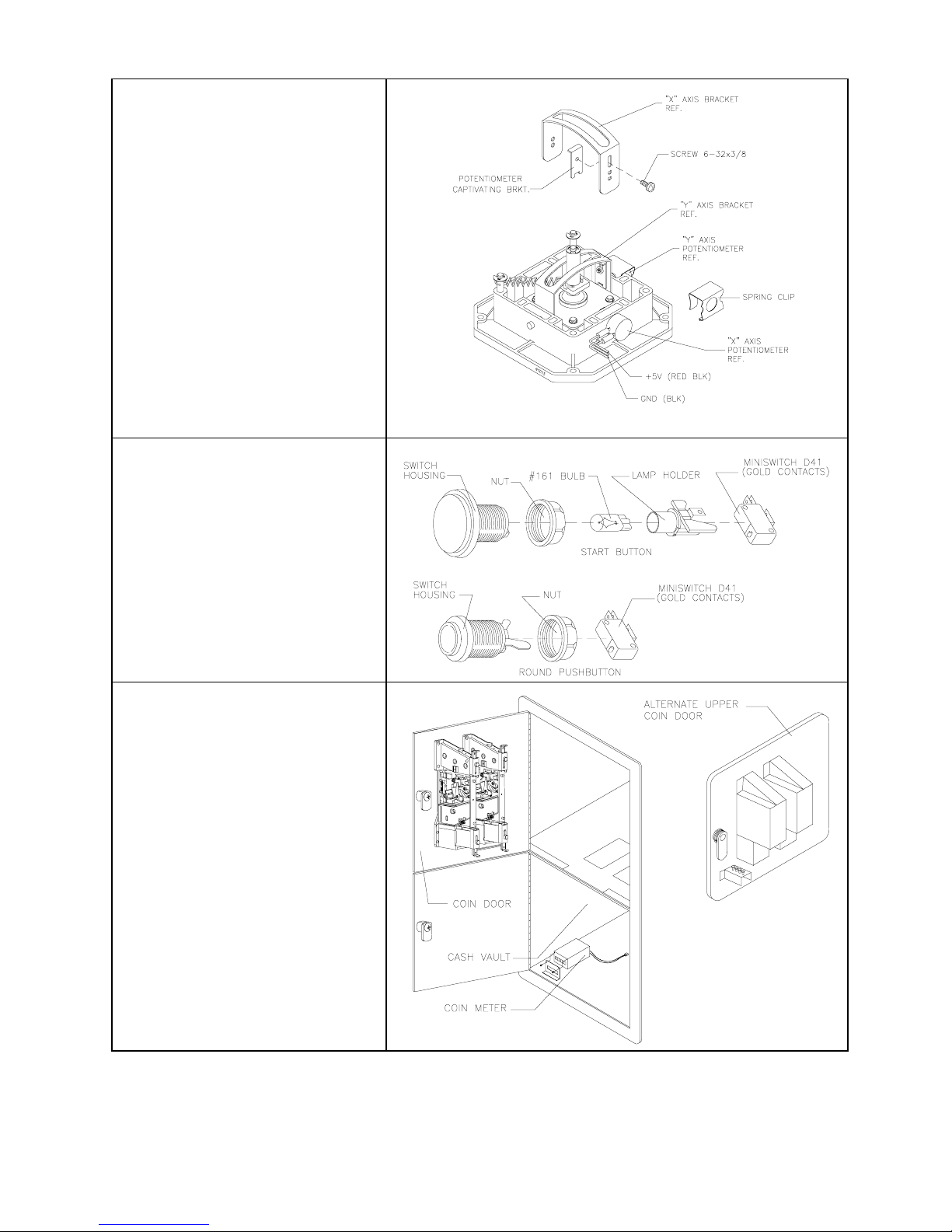
Joystick Assembly
Open control panel. Label and
disconnect joystick wiring harness.
Loosen and remove four nuts holding
joystick to control panel. Lift joystick
assembly out of control panel.
To remove potentiometer, pull
bottom of spring clip out to unlatch
and pull clip up to remove. Pull
potentiometer away from assembly
gently to release.
When replacing potentiometer, seat it
snugly in its housing, flush against
plastic base. If you have seated it
properly, you should be unable to
rotate the potentiometer more than a
degree or two by hand.
Push Buttons
Open control panel. Label and
disconnect wires. Separate switch
from its pushbutton. Bend large
prong away from switch just enough
to slide switch off housing.
To remove light inside START
button, pull light bulb up and out of
socket.
Coin Meter
Open cash vault door. Label and
disconnect meter wiring. Unscrew
two front mounting screws. Record
meter count before testing or
replacing.
Coin Mechanism
Unlock coin door and swing open.
Unlatch and remove each coin
mechanism separately to clean or
replace with different type. Ensure
mechanism seats fully in holder upon
reinstallation. Close and lock release
latch, then close door. Turn AC
power ON and change mechanism
setup. Then test known good and
bad coins to verify operation.
Service - 4 Midway Games West Inc.
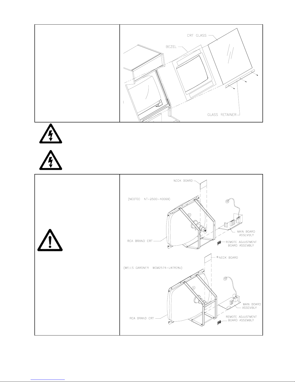
Viewing Glass
Pull control panel upward to expose
glass retainer strip. Hold viewing
glass in place and remove retainer
screws. Slide glass upward a bit and
swing bottom outward until free f rom
cabinet. Slowly slide glass down until
free from cabinet. Set in safe place.
Monitor Bezel
Remove viewing glass. Grasp
monitor bezel at bottom and lift down
out of groove. Remove bezel from
cabinet. To replace, slide top of bezel
into cabinet groove first. Swing
bottom into position.
CAUTION:
CRTs and their power supplies can retain energy long after power is off–
especially when a defective circuit prevents a normal discharge. Connect well-insulated
ground strap to metal chassis. Slide free end of strap under CRT anode cap until you
make contact. Wait two minutes for charge recovery, then discharge anode again.
CAUTION:
Monitor does not require isolation from AC line voltage during normal
operation. However, when operating outside cabinet or servicing monitor on a test
bench, isolate monitor from line voltage with isolation transformer.
Monitor
Remove viewing glass and monitor
bezel. Disconnect monitor from
wiring harness and ground wires.
Remove four ¼-20 flange nuts
securing monitor m ounting flanges to
mounting panel. Pull monitor
carefully from cabinet and set aside.
WARNING:
Video
monitor is heavy, with most weight
toward front of assembly. Be sure to
firmly support monitor as you remove
it from cabinet.
Skins Game Service - 5
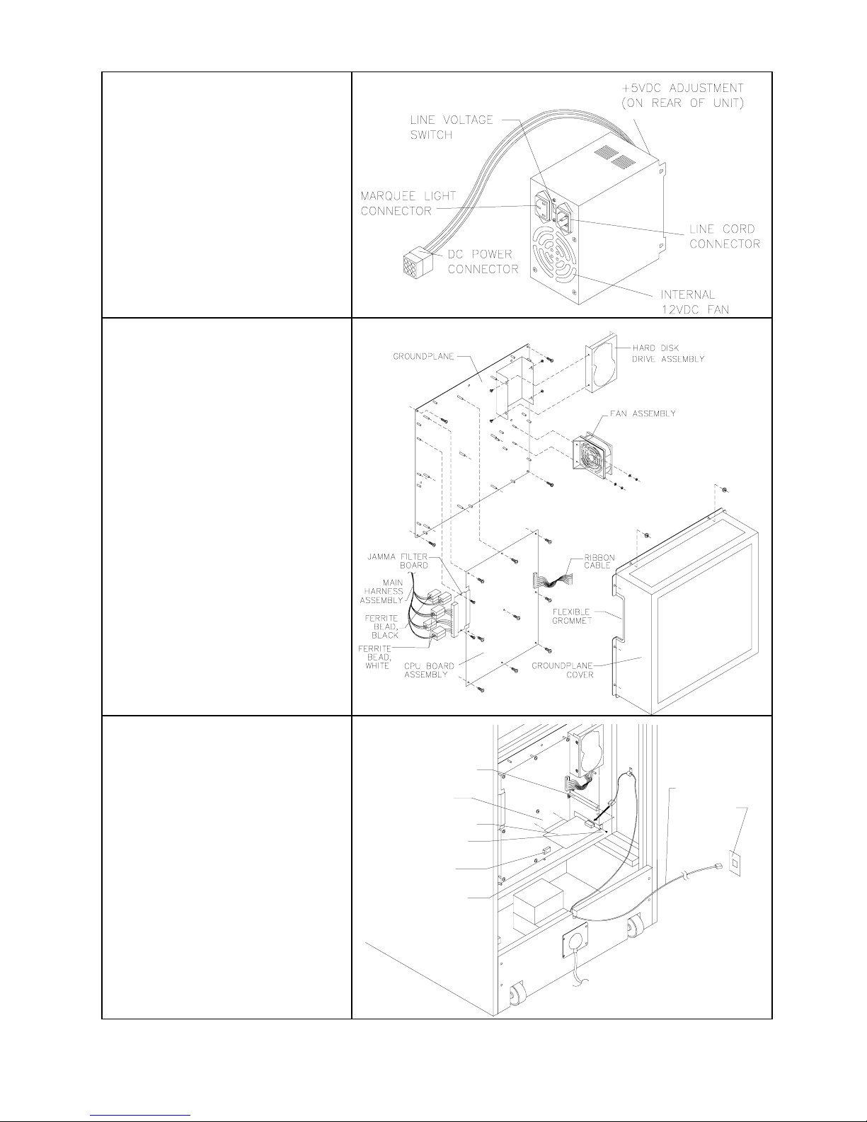
Power Supply
Remove rear door. Unplug IEC AC
connector from rear of power supply.
Unplug DC connector from front of
power supply. Remove two front and
two rear screws from power supply.
Lift power supply off power chassis.
Note AC input voltage setting.
To reinstall power supply, set AC
voltage switch to correct value. Set
supply on power chassis and align
mounting holes. Install four screws
and two power connectors.
Fan Assembly
Remove rear door. Remove hex nuts
on groundplane cover. Remove
cover and set in safe place.
Disconnect wiring harness and
remove mounting hex nuts and
washers. Remove fan from cabinet.
Hard Disk Drive
Remove groundplane cover and set
in safe place. Disconnect wires from
hard drive and remove bracket
mounting screws. Gently remove
hard drive from bracket. Store and
transport hard drive in anti-static bag.
CPU Board Assembly
Remove groundplane cover and set
in safe place. Disconnect wires from
harness. Remove mounting screws.
Battery
Lithium battery sits on top of
timekeeper IC. Carefully pry off
battery and replace with identical
type.
Modem Card
Remove groundplane cover. Remove
modem cable from modem card.
Remove modem mounting screw.
Carefully remove modem card from
PCI slot without excessive rocking
motion.
Ensure tight connection when
replacing modem cable into modem
card.
PCI POST
PCI SLOT
MODEM CARD
MOUNTING SCREW
BATTERY
MOUNTING SCREW
MODEM CABLE
WALL JACK
Service - 6 Midway Games West Inc.

ALTERNATE CASH MECHANISM INSTALLATIONS
The Mars 2451 Bill Validator is factory installed, but you can replace it with any of the following options.
Mars VFM2-L2 Bill Validator
1. Before installing MARS dollar bill validator, take off cover by removing two screws holding it.
2. Set DIP switches as follows:
Switch #1 On (Accepts $1.00)
Switch #2 On (Pulse pattern 50 ms On/300 ms Off)
Switch #3 Off (Rejects $5.00)
Switch #4 On (Not Used)
Switch #5 Off (Number of pulses/dollar–1)
Switch #6 Off (Number of pulses/dollar–1)
Switch #7 Off (Number of pulses/dollar–1)
Switch #8 Off (Bill orientation–accepts in both directions)
3. Replace cover and secure into place with screws.
4. Locate 18-pin connector/jumper (part no. 5797-13606-00), supplied in cashbox. Plug connector into
bottom of dollar bill validator through opening in cover.
5. Turn AC power OFF and open coin door.
09-96026-33 Coin Door
6.
Remove four (4) nuts holding top plate to coin door. Save nuts.
Remove top plate
Place finished dollar bill validator face down on coin door on four (4) pem studs.
Place cable clamp on lower pem stud. Orient cable clamp “down.”
Replace and tighten four (4) nuts previously removed.
7. Plug male 9-pin connector from dollar bill acceptor into female 9-pin connector in VGM (located next
to coin door).
1. Set DIP Switches 1 and 6 to ON.
9. Close coin door. Turn AC power ON. Insert several dollar bills to confirm they are accepted and
proper credits given.
10. Open coin door and ensure validator aligns with bill chute and bills do not remain in validator.
Tekbilt NV110-GA1 Bill Validator
1. Before installing TEKBILT dollar bill validator, set DIP switches (located on top of validator) as follows:
MODE DIP SWITCH NUMBERS
1 234
1 credit per acceptance Off Off Off ---Slow pulse 50msL/300msH ---- ---- ---- On
2. TEKBILT requires separate adapter plate (adapter supplied with VGM). Mount adapter plate of dollar
bill validator using four 6-32 nuts.
3. Turn AC power OFF to VGM and open coin door.
4. 09-96026-33 Coin Door
A. Remove four (4) nuts holding top plate to coin door. Save nuts.
B. Remove top plate.
C. Place finished dollar bill validator face down on coin door on four pem studs.
D. Place cable clamp on lower pem stud. Orient cable clamp “down.”
E. Replace and tighten four (4) nuts previously removed. continued
Skins Game Service - 7

5. Plug male 9-pin connector from dollar bill acceptor into female 9-pin connector in VGM (located next
to coin door).
6. Set DIP Switches 1 and 6 to ON.
7. Close coin door. Turn AC power ON. Insert several dollar bills to confirm they are accepted and give
proper credits. There should be one pulse per dollar on center coin chute.
Note: If credits do not correctly register, swap red and white wires on validator side.
8. Open coin door and ensure that validator aligns with bill chute and bills do not remain in validator.
Dixie-Narco Up-Stacker
You can install a DBV with a vertical dollar bill stacker into your VGM. The following information instructs
you as to which stacker you can use and how to install it.
You must perform installation with AC power OFF and power switch in OFF position.
1. Install only the following vendor and model numbers:
A. Dixie-Narco USA-15 (12-pin connector)
Model: 88X5003
Software: 57X300-20
B. Williams Part Number 09-47000
Dixie-Narco (9-pin connector)
Model: 88X5014 (DBA1US)
Software: 57X300-20
2. DIP Switch Settings
Williams 09-47000 Dixie-Narco USA-15
Switch #1: Open Switch #1: Open
Switch #2: Closed Switch #2: Open
Switch #3: Open Switch #3: Open
Switch #4: Open Switch #4: Open
3. Installation (to coin door):
A. Remove four (4) nuts holding bottom plate to coin door. Save nuts.
B. Remove bottom plate.
C. Remove (2) nuts holding upper plate on. Save nuts.
D. Remove one spacer, each from the two top pem studs.
E. Attach these spacers to the bottom pem studs.
F. Place item 3 face down on coin door on the four (4) pem studs.
G. Place ground (green) wire, coming from the upstacker, on pem stud.
H. Secure item 3 with the four (4) nuts (removed previously in step A) on pem studs.
4. Cable Connection:
A. Dixie-Narco Stacker w/9-pin Connector (Williams P/M 09-47000)
Plug 9-pin connector from stacker into 9-pin female connector inside cabinet.
B. Dixie-Narco Stacker w/12-pin Connector
1. Take jumper cable H-17019 (9-pin to 12-pin) supplied with VGM and mate 9-pin connector
with 9-pin plug in cabinet, located by coin door opening.
2. Take 12-pin from jumper cable and mate with 12-pin connector on stacker cable.
3. Dress cable from stacker away from cash box area.
Service - 8 Midway Games West Inc.

CHAPTER
SYSTEM SOFTWARE
NOTICE:
the right to make improvements in equipment function, design, or components as progress in
engineering or manufacturing methods may warrant.
This manual is subject to change without notice. Midway Games West Inc. reserves
 Loading...