


http://www.midway.com
DECEMBER 1999
16-20035-101
TM
Sit-In,
Dedicated
27” Video
Game
Operation Manual
•1-Setup •2-Operation •3-Audits •4-Wiring •5-Servicing •6-Troubleshooting •7-Parts
Midway Games Inc., 3401 North California Avenue
Chicago, Illinois 60618–5899 USA
-
QUICK-START LINKING GUIDE
NOTICE:
unique
Adjustments Menu
NOTICE:
Before completing ins tallation, verify that each cabin et has
ID. Otherwise the link won’t function. For further information, see
in Chapter Three of the operation manual.
To link three or four cabinets, you must use an Ethernet hub.
a separate and
Linked Play
SET UP THE LINKS
[ ] 1. Switch off power to all cabinets. Rem ove cab inet ac cess doors a nd link ing cables . Ch eck c abinet
linking cables. One end of each linking cable must attach to the Arcade Computer’s network
interface jack.
[ ] 2.
[ ] 3.
[ ] 4. Turn on cabinet power.
To link two cabinets:
(You’ll find a coupler in a Manila envelope, inside the cashbox .)
To link three or more cabine ts:
rear of the cabinets. Connect all linking cables. When you use a hub,
If you’re onl y linking two cabinets, us e one coupler. You don’t need a hu b.
You need to add a h ub to your network. Plac e the hub near the
don’t
use any couplers.
ADJUST GAME OPTIONS
CAUTION:
power on. Otherwise, you may damage the electronics and void your warranty.
[ ] 1. Find the diagnostic switches behind each cabinet’s coin door. Press and hold each cabinet’s
TEST MODE button to enter the Menu System.
[ ] 2. From each cabinet’s Operator Menu, select the Adjustments Menu.
[ ] 3. From each cabinet’s Adjustments Menu, select the Linked Play Adjustments Menu.
[ ] 4.
[ ] 5.
[ ] 6.
[ ] 7.
[ ] 8.
LINKED PLAY.
UNIT ID.
for each cabinet.
EXIT
RESTART ALL CABINETS.
TEST THE SYSTEM .
Each cabinet mus t have a uniqu e unit I D. Set the option UNIT ID to a separ ate num ber
the menu system. If you changed any unit IDs, turn off all machines.
Don’t connect or disc onnect ca bles to th e game el ectronics or hub wit h the
At each cabinet, set the LINKED PLAY option to YES.
After the machines reinitialize, they’ll operate in Linked Mode.
Test the network b y playing a Linked Mode gam e on all linked m achines.
ii-
-
iii--iv-


2
))52$'
7+81'(5
&+$37(5
TM
SETUP
Fill out and mail in the Game Information Card. Include the product serial number from the label
on the rear of the cabinet. For your records, write the product serial number in the manual.
SERIAL NUMBER _____________________________________________________________
NOTICE:
The term VGM refers to the video game machine.
Setup 1-1
SAFETY INSTRUCTIONS
The following safety instructions apply to operators and service personnel. Read these instruc tions before
preparing your VGM (video game machine) for play. Other safety instructions appear throughout this
manual.
DEFINITIONS OF SAFETY TERMS
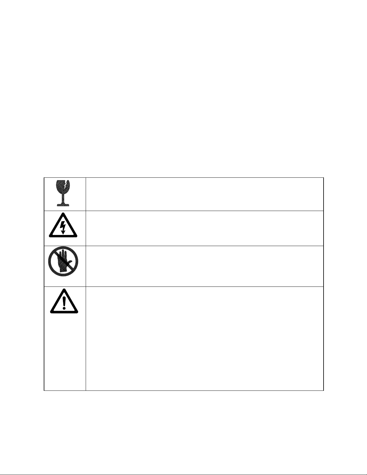
DANGER
injury.
WARNING
injury.
CAUTION
injury. CAUTION also alerts you about unsafe practices.
NOTICE
indicates an imminent hazard. If you fail to avoid this hazard, it will cause death or serious
indicates a potential hazard. If you fail to avoid this hazard, it could cause death or s erious
indicates a potential hazard. If you fail to avoid this hazard, it may cause m inor or moderate
indicates information of special importance.
WARNING: TRANSPORTING VGMS.
devices. Use appropriate care when transporting this VG M. Avoid rough handling when
moving the cabinet. Don’t move this VGM with the power on.
WARNING: DISCONNECT POWER.
before attempting service or adjustments. Installing or r epairing PC boards with power
ON can damage components and void the warranty. Be sure that you securely install
ground wires.
WARNING: GROUND VGMS
have inspected and properly grounded it. Only plug this VGM into a gr ounded, threewire outlet. Don’t use a “cheater” plug, or cut off the ground pin on the line cord.
. Avoid electrical shocks ! Don’t plug in a VGM until you
This VGM contains glass and fragile electronic
Always turn the power OFF and unplug the VGM
WARNING: HAZARD TO EPILEPTICS.
condition which may cause epileptic seizures or momentary loss of consciousness
when viewing certain kinds of flashing lights or patterns that are present in our daily
environment. These persons experience seizures while watching some television
pictures or playing certain video games. People who have not had seizures may
nonetheless have an undetected epileptic condition.
If anyone in your family has experienced symptoms linked to an epileptic condition
(e.g., seizures or loss of awareness), consult your physician before using video games.
Parents should observe their children while they play video games. If you or your child
experience the following symptoms: dizziness, altered vision, eye or muscle twitching,
involuntary movements, loss of awareness, disorientation, or convulsions, discontinue
use immediately and consult your physician.
Setup 1-2
A small portion of the population has a

WARNING: AVOID ELECTRICAL SHOCKS
an isolation transformer. Internal, cabinet AC isn’t isolated from the external, AC line.
. This video game m a chine does not utilize
WARNING: HANDLE FLUORESCENT TUBE AND CRT WITH CARE.
fluorescent tube or CRT and it break s, it will im plode! Shatter ed glass can fly eight feet
or more from the implosion.
CAUTION: CHECK POWER SELECTOR.
supply for the correct line voltage. Check the selector setting before switching on the
VGM.
CAUTION: USE PROPER FUSE.
of the same type as those they replace. Fuse voltage and cur rent ratings must match
ratings on the original fuse.
CAUTION: ATTACH CONNECTORS PROPERLY.
(PCB) connectors mate pr operly. If connectors don’t slip on easily, don’t force them. A
reversed connector may damage your VGM and void the warranty. Connector keys only
allow a connector to fit one set of pins on a board.
CAUTION: TAKE CARE WHEN SHIPPING HARD DISKS.
packed in an anti-static bag. When shipping the drive f or repair or r eplacement, pack it
in an approved container (P/N 08-8068). Never stack or drop hard disk drives.
NOTICE:
equipment improvements as engineering progress warrants.
This manual is subject to change without notice. Midway reserves the right to make
Avoid electrical shock! Replacement fuses m ust be
Set the 110/220VAC selector on the power
Be sure that printed circuit board
The hard disk drive m us t be
If you drop a
PRODUCT SPECIFICATIONS
Operating Requirements
Location
Domestic
Foreign
Japan
Cabinet Statistics
Shipping Dimensions
Cabinet
Width
Depth
Height
Equipment Characteristics
Video Monitor
Medium Resolution RGB
27” (63.5 cm) CRT
Electrical Power
120VAC @ 60Hz 4.0 Amps
230VAC @ 50Hz 2.0 Amps
100VAC @ 50Hz 4.0 Amps
32.0" (81.3 cm)
42" (169 cm)
76.0" (193 cm)
Temperature
32°F to 100°F
(0°C to 38°C)
Shipping Dimensions
Seat Pedestal
Width
Depth
Height
Audio System
Digital Stereo Sound
Two 5.5” (14 cm) and
One 6.5” (16.5 cm) Spkr
Setup 1-3
22.0” (55.8 cm)
36.0” (91.4 cm)
51.0” (130 cm)
Humidity
Not to exceed 95% relative
Shipping Weight
Cabinet
Boxed, 360 lbs. (163 kg.)
Seat pedestal
Boxed, 125 lbs. (56.8 kg.)
Currency Acceptors
2 Coin Mechanism, Coin Counter
Dollar Bill Validator Ready
Electronic Coin Acceptor Ready
PRODUCT CONFIGURATION
•
Standalone Units
Each VGM (video game machine) is ready to play right out of the box. You can use the VGM Menu
System to set player variables in advance. Or you can leave these choices to players.
•
Linked Units
Linking allows players to compete against each other (on one c ourse). O perator m enus are the sam e
as in stand-alone VGMs. W ith a coupler and linking cable, you can connect two VGMs. (You can
connect up to four VGMs with the optional Hub Link ing Kit.) You’ll find a coupler in the spare parts
envelope. Look in the cashbox. The linking cable is factory installed.
INSTALLATION & INSPECTION
WARNING:
plastic parts.
[ ] 1. Remove and set aside items from the s hipping containers. Remove all pack ing material. Inspec t
for damage. Check the main cabinet exterior, the control section and the seat pedestal.
[ ] 2. Remove the keys from the steering wheel. Unlock and open the coin, cash box, and rear doors.
You’ll find electrical cords, mechanical components, and VGM spare parts inside the cash box.
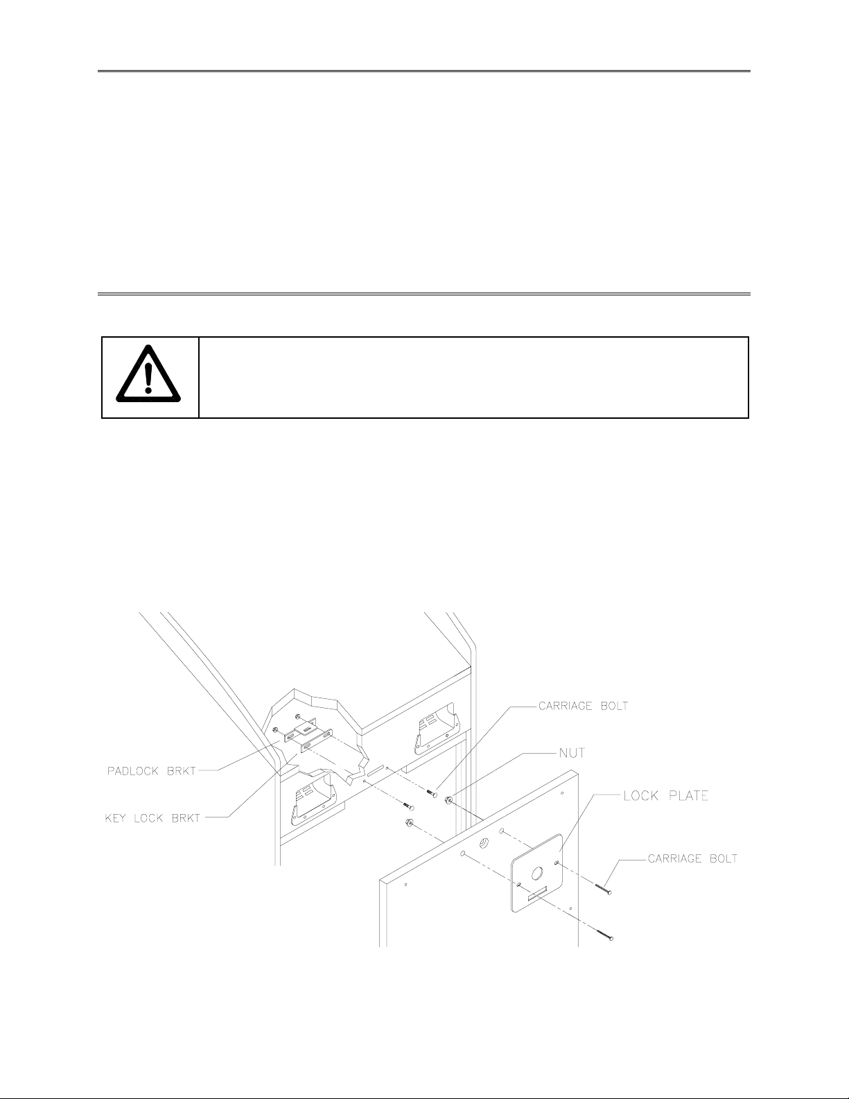
[ ] 3. You can install an extra padlock to s ecure the r ear door. You’ll find a hasp in the spare parts bag.
Remove the two lock brack et nuts f rom ins ide the cabinet, above the rear door opening. Slide the
hasp onto the bolts. Now the hasp should protrude from the hole in back of the cabinet. Reinstall
and tighten nuts.
The cabinets are top-heavy. While moving the cabinets, don’t push against
CABINET SECURITY MODIFICATIONS
[ ] 4. Modify the lock plate at the top of the rear door. Remove the bolts and nuts from the lock plate.
Rotate the plate so that the slot will be above the door. Reinstall and tighten the bolts and nuts.
Setup 1-4
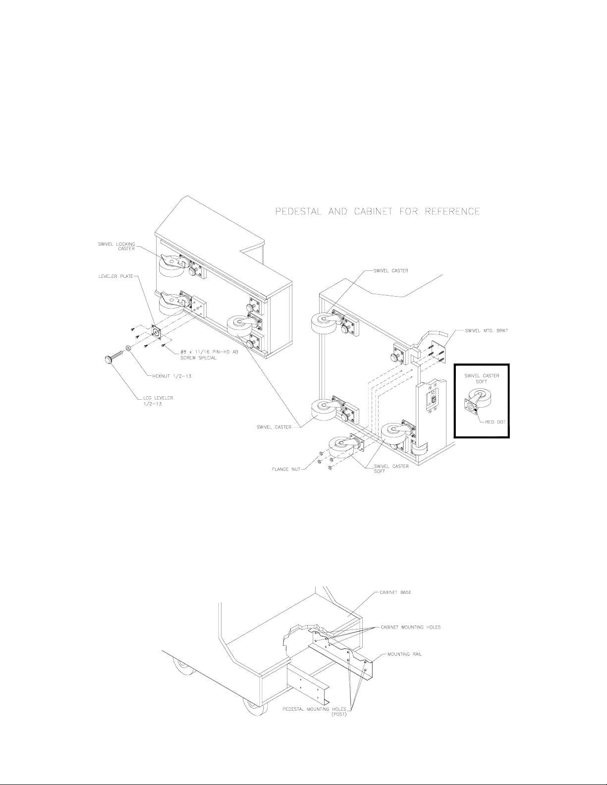
[ ] 5. Install one nut onto each leg leveler. Tilt the cabinet onto its side. Locate four threaded holes
under the cabinet. Install a leveler and nut into each hole. Don’t tighten the nuts yet.
[ ] 6. Tilt the seat pedes tal onto its side. Locate three thr eaded holes under the seat pedestal. Install a
leveler and nut into each hole. Don’t tighten the nuts yet.
[ ] 7. Locate the cas ter wheel assemblies. Attach one caster onto each group of threaded studs. T he
cabinet uses four swivel caster s. The seat pedestal uses three. Place the swivel c aster in front.
Place two locking casters in back. Tighten the caster mounting nuts very firmly.
INSTALL CASTERS AND LEVELERS
[ ] 8. Stand the cabinet upright and make certain that it rests in a stable pos ition. Move cabinet to its
play location. Maintain clearance between the cabinet and walls, drapes, other VGMs, etc. Lower
each leg leveler until the cabinet is stable and level. Adjust the levelers to raise the wheels up off
the floor. Distribute the cabinet’s weight equally on each corner. Tighten the leveler nuts.
[ ] 9. Install the rear door. Close and lock this door. Leave the other doors open for now.
LOCATION OF SEAT PEDESTAL MOUNTING HOLES
1-5
[ ] 10. To protect seat pedestal mounting rails dur ing shipm ent, the f actory bolts them ins ide the cabinet.
Remove the 1/4-20 hex-head bolts that sec ure the rails. Slide the rails partway out of the bottom -
front cabinet opening. (See the nearby diagram for proper placement.)
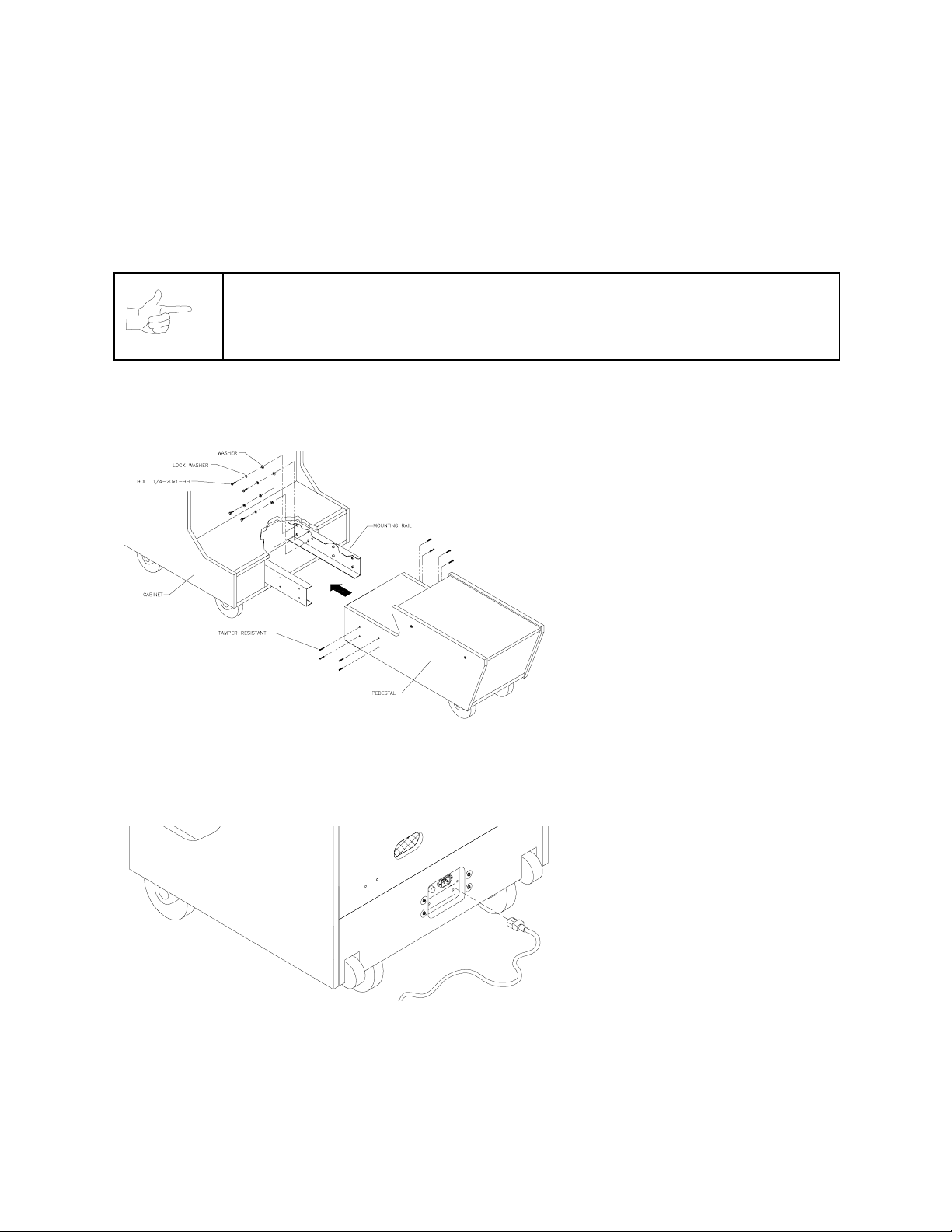
[ ] 11. Fasten down the rails in this new position. Firmly tighten the rail bolts, but don’t torque them down.
Slide the seat pedestal onto the rails. Vertically position the rails. Remove the seat pedestal.
Tighten the rail bolts with a wrench.
NOTICE:
[ ] 12. Roll the seat pedestal near the cabinet. Leave enough space to attach the wiring harness. Mate
each seat pedestal cable connector with its cabinet c able connector. Press connectors firm ly to
seat contacts.
When you install the seat pedestal, take care to avoid pinching wires!
[ ] 13. Align the seat pedestal
opening with the rail ends.
Slide the seat pedestal
forward onto the extended
mounting rails. Align holes.
Attach the seat pedestal using
1/4-20, tamper-resistant
screws and large flat
washers. You’ll find a T27
wrench with the spare parts.
Use it to tighten these screws
firmly.
[ ] 14. The power cord is in the
cashbox. Match the holes on
the IEC plug with the prongs
in the receptacle. Push the
plug firmly to seat it.
INSTALL THE LINE CORD
[ ] 15. Before you plug in the VGM,
verify line voltage compatibility with the machine. Then
plug the VGM into a grounded
(3-terminal) AC wall outlet.
Switch on the VGM at the
on/off switch. (This switch is
on the cabinet roof. Face the
cabinet’s back. Find the on/off
switch to your right.) The
VGM will power up and begin
self-diagnostics. If diagnostics
find no errors, the VGM
enters Attract Mode. (Racing
scenes and sounds, player
scores, messages, etc.)
1-6
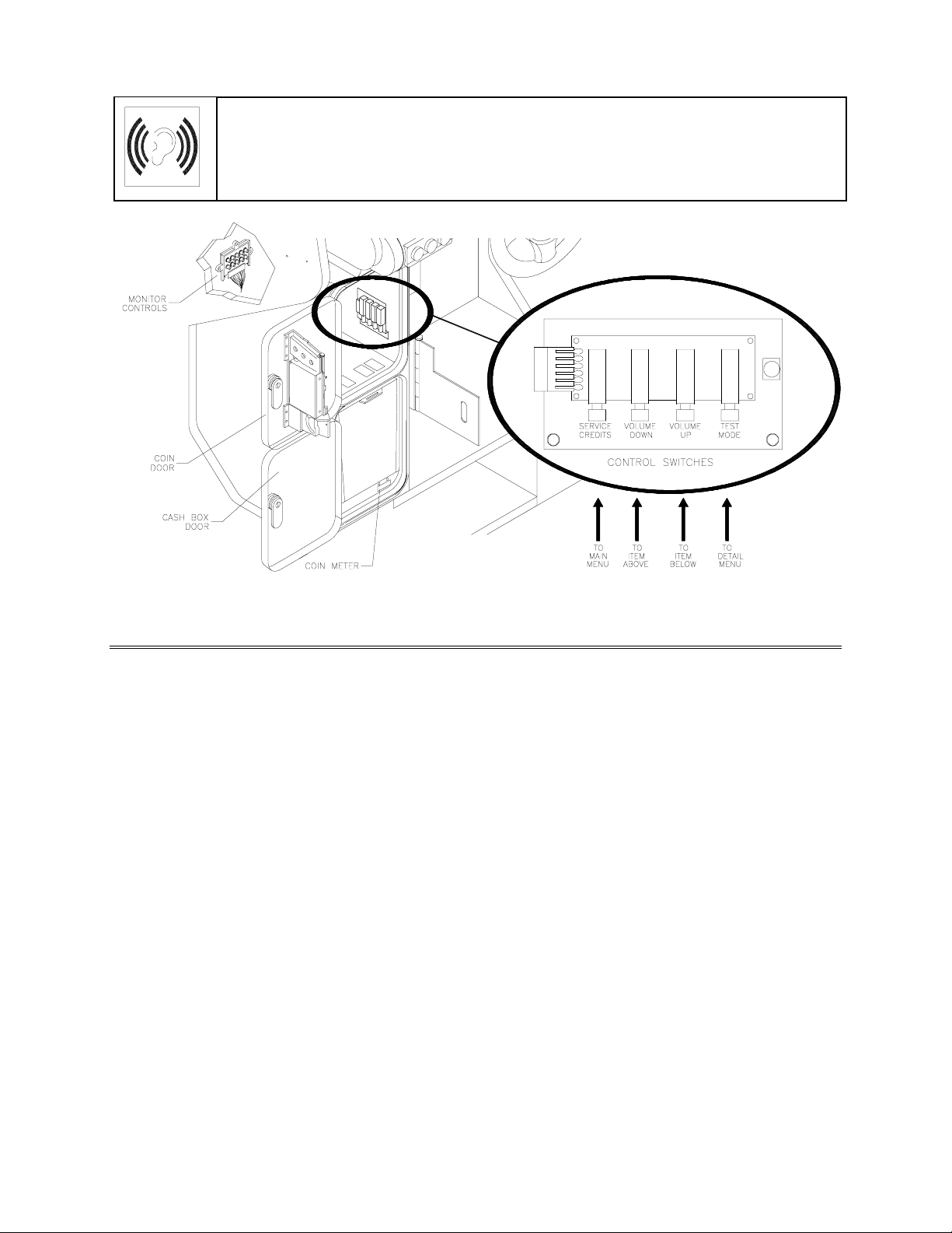
[ ] 16. Unlock and open the coin door. Locate the control switches. Press TEST MODE to enter the
Menu System.
[ ] 17. Select “DISK T ESTS” at the Diagnostics Menu. Run all the tests in order to verify correct drive
operation.
[ ] 18. Select “SWITCH TESTS” at the Diagnostics Menu. Check to be sure that all control switches
work.
[ ] 19. Select “SOUND TESTS” at the Diagnostics Menu. Verify operation of each speaker.
[ ] 20. Select “FORCE FEEDBACK TESTS” at the Diagnostics Menu. Verify the presence of steering
resistance.
[ ] 21. Select “CALIBRATE CONTROLS” at the Main Menu. Set steering and throttle lim its for m axim um
accuracy.
[ ] 22. Select “START THE GAME” at the Main Menu. The system should enter Attract Mode. O pen the
coin door and press the SERVICE CREDITS button to allow game play. Press the START button
to begin play. Listen to the audio while playing the game. Note sound irregularities (phase
problems, no low frequencies, mono audio f rom stereo speakers, etc.). If necessary, check the
wiring harness for internal shorts or strapped connections.
[ ] 23. Change the volume and make adjustments as neces sary. Close and lock all open doors. T ighten
the leveler nuts. Engage the caster locks.
LINKED OPERATION
Equipment Requirements
Linked Mode permits players to compete between networked cabinets in real time. The link ing program is
player selectable, so that each cabinet serves player needs.
To achieve linked operation, you must connect cabinets. The factory installs one linking cable in each
cabinet.
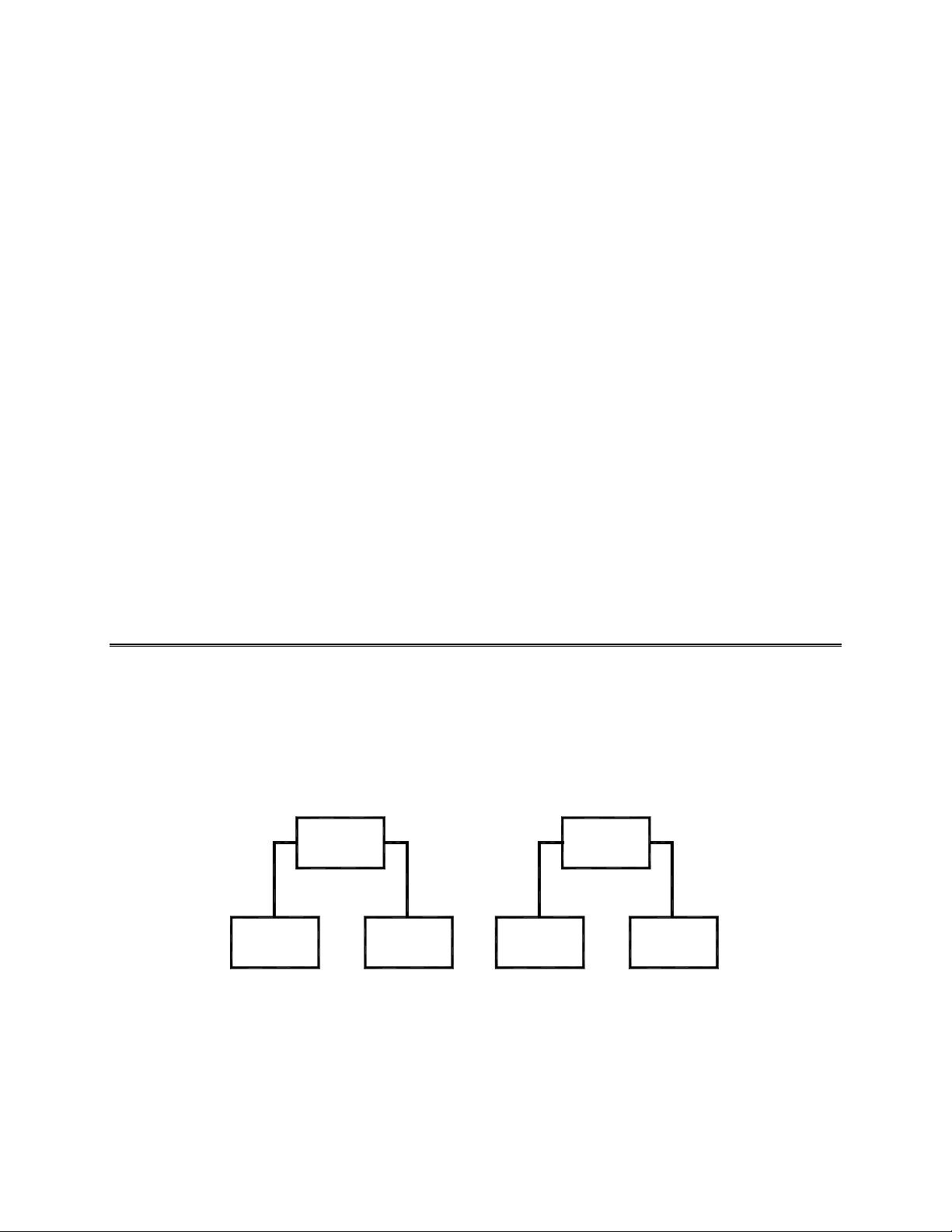
Coupler
Cabinet
1
Cabinet
2
Cabinet Cabinet
Link Two Cabinets with a Coupler
TO LINK TWO CABINETS,
•
connect two cabinets together. Use only one coupler between each pair of cabinets. The coupler
employs passive electronics. Pass ive electronics limit the cable length and number of cabinets that
you can link. Most operations attach linked cabinets , but you can separate cabinets by up to 25 feet.
You can add linked cabinet pairs as necessary.
use a crossover coupler. All cabinets contain a crossover coupler to
Coupler
34
1-7
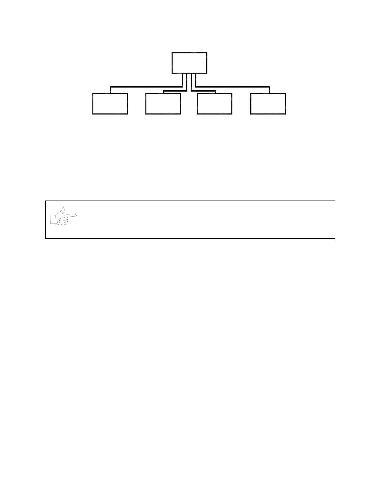
Network
Hub
Game
12
Game Game
3
Game
4
Link Up to Four Cabinets with a Hub
•
TO LINK MORE THAN TWO CABINETS,
use a network hub. Notice that the hub replaces the
coupler between cabinets. Each hub can connect several cabinets. In fact, the hub’s active electronic s
permits use of large network s. You can add linked cabinets as necessar y. The network hub’s active
circuits also allow you to use long cables. Most operations attach linked cabinets, but you can
separate cabinets by up to 300 feet.
•
THE DELUXE LINKING KIT (M odel 25735)
contains a lighted, overhead sign and cabinet connector
brackets.
NOTICE:
You can’t link more than four cabinets.
Networking Pointers
•
Protect exposed wiring from player foot traffic, c leaning crews, service personnel, etc. Use approved
conduit or wire channels to support cables. Network modular connectors don't include strain relief.
•
Keep cables away from heat, moisture and electromagnetic fields. (Avoid neon signs, fluorescent
fixtures, two-way radios, cordless telephones, power circuits, speaker wiring, etc.).
•
Universal RJ-45 modular plugs aren't keyed, numbered, or coded. Clearly mark cabinet network
connections. Otherwise, someone could confuse them with computer or telephone circuits.
•
The f actory supplies network cables with the cabinets. Thes e cables will reach the hub in network s of
four or fewer cabinets.
•
Use only Category 5, twisted pair cable.
•
If you want to monitor network activity, you can locate the hub remotely. You can use long cables, if
they satisfy these requirements: (1) Cables m ust not exceed a length of 328 feet or 100 meters. (2)
Cables must be Category 3 (or higher), 100 ohm, unshielded, twisted pair, communications-grade
wiring. (3) You must not use standard telephone cables.
1-8

Wiring the Network
NOTICE:
won’t operate properly.
[ ] 1. Raise the leg levelers. Roll the cabinets to their destination. Lower the leg levelers.
[ ] 2. Verify VGM operation. Make necessary repairs or adjustments before making changes to the
cabinets.
[ ] 3. Shut down all machines.
[ ] 4. Place the hub near the center of the linked cabinet array.
[ ] 5. You’ll find a linking cable coiled up inside each cabinet. Cut the cable tie. Loc ate the cable’s free
end. Uncoil enough cable to reach the hub through the rear box of the cabinet.
[ ] 6. Check the other end of the cable. It should attach to an Arcade Computer network jack. You’ll find
this jack in the middle cabinet box.
[ ] 7. Recoil and retie the remainder of the cable. Repeat the cable connection steps at the other
cabinets.
[ ] 8. Plug the cabinet linking cables into any of the jacks on the hub rear panel.
[ ] 9. Plug the hub’s AC power adapter into its jack on the hub.
Don't use crossover couplers in a hub installation. Otherwise, your network
[ ] 10. Set the hub front panel switch to the LNK (link) position.
[ ] 11. Retract excess cable into the cabinet coils so that the cables don't touch the floor. Retracting the
cable keeps it away from cabinet wheels during relocation.
[ ] 12. Connect the AC Adapter and line cords to AC power. Turn on each of the cabinets. Exam ine the
screens of all cabinets.
CAUTION:
power on. Otherwise, you may damage the electronics and void your warranty.
[ ] 13. Restart all machines.
[ ] 14. The cabinets will begin the Power-On Self T est. If the test doesn’t find any errors, each cabinet
enters its Attract Mode automatically.
[ ] 15. Start up linked cabinets and ensure that each cabinet's player controls aff ect the sam e vehicle on
all screens. The CPU and hub LEDS will indicate communication activity between the two
cabinets.
[ ] 16. Clos e and lock the coin doors. Reinstall and lock the r ear cabinet doors. Lower all leg levelers
until wheels lift off of the floor. Then level the cabinets.
Don’t connect or disconnect cables to the VGM electronics or hub with the
Network Software Setup
[ ] 1. Unlock the coin doors of all cabinets.
1-9

[ ] 2. Find the diagnostic switches behind each cabinet’s coin door. Press and hold each cabinet’s
TEST MODE button to enter the Menu System.
[ ] 3. From each cabinet’s Operator Menu, select the Adjustments Menu.
[ ] 4. From each cabinet’s Adjustments Menu, select the Linked Play Adjustments Menu.
[ ] 5.
[ ] 6.
[ ] 7.
[ ] 8.
[ ] 9.
LINKED PLAY.
UNIT ID.
for each cabinet.
EXIT
RESTART ALL CABINETS.
TEST THE SYSTEM.
Each cabinet must have a unique unit ID. Set the option UNIT ID to a s eparate number
the menu system. If you changed any unit IDs, turn off all machines.
At each cabinet, set the LINKED PLAY option to YES.
After the machines reinitialize, they’ll operate in Linked Mode.
Test the network by playing a Linked Mode game on all linked machines.
1-10

2
))52$'
7+81'(5
&+$37(5
TM
NOTICE:
OPERATION
The term VGM refers to the video game machine.
Operation 2-1

GAME OPERATION
STARTING UP
Whenever you turn on the machine or restore power, the system executes boot ROM code. The boot
ROM contains self-diagnostic tests. These tests autom atically verify and report the condition of the CPU
and other hardware. If the hardware fails a test, the system displays an error message.
Having passed power-up tests, the system enters Attract Mode. Attract Mode consists of typical game
scenes and sounds, alternating with high scores. Attract Mode continues until game play commences.
Players insert currency or tokens to start the gam e. Each player selects a truck and a cour se. Play begins
after a countdown period. The game will progress until players quit or exhaust their playtime. At GameOver Mode, players may choose to begin again. If players choose not to continue, then the system returns
to Attract Mode.
ARCADE COMPUTER
This game uses an Arcade Computer to control its functions. The Arcade Computer is a customized
personal computer. Housing the Arcade Computer is a PC-like case. Inside, you’ll recognize the
motherboard, plug-in cards, modular power supply, disk drives, etc. Despite these familiar features,
Midway optimized this computer specifically for this game. The Arcade Computer design permits improved
upgradability and service access without sacrificing ruggedness or reliability.
PLAYER CONTROLS
ACCELERATOR.
•
•
BRAKE.
•
•
GEARSHIFT.
•
player may choose manual or automatic shift operation. Manual shift operation requires the player to
upshift while accelerating and downshift while decelerating. (T his shift has no reverse gear.) Players
select automatic or manual shift truck s before racing. Manual shift trucks allow skilled drivers more
control and faster starts.
NITRO BUTTON.
•
pressing NITRO adds a power burst. (The button illuminates when nitro is available.)
START BUTTON
•
trucks, etc.
STEERING WHEEL.
•
SLAM CAM.
•
seat inside the truck.
CRASH CAM.
•
viewpoint is from above and behind the truck. A truck camera would see this view.
CHOPPER CAM.
•
viewpoint is from above and behind the truck. A tracking helichopper camera would see this view.
The brake pedal stops the vehicle, just like a real brake.
The accelerator pedal controls vehicle speed and acceleration.
The gearshift lever controls the amount of engine torque that reaches the wheels. The
The NITRO button is on the end of the shift lever. If the nitro feature is active,
. The START button allows a player to begin or continue play, select courses and
The steering wheel aims the vehicle and provides course condition feedback.
The red SLAM CAM button displays the cockpit view. The viewpoint is from the driver’s
The orange CRASH CAM button provides a close-up, aerial view of the cours e. The
The yellow CHOPPER CAM button provides a distant aerial view of the c ours e. The
Operation 2-2

Player Panel Controls
OPERATOR CONTROLS
CABINET CONTROLS
•
DIP Switches
factory use only. Keep them set at their default value, all off. You can adjust game var iables, check
bookkeeping totals and perform diagnostics with diagnostic control switches.
•
The Monitor Remote Control Board
•
The Cabinet POWER Switch
•
The Computer POWER Swit ch
procedures, leave this switch on. Use the main power switch to control the power.
DIAGNOSTIC CONTROL SWITCHES
•
The SERVICE CREDITS Button
Menu System occasionally assigns a function to SERVICE CREDITS. Check screen directions for
these additional functions.
on the MagicBus Board set some system variables. These DIP switches are for
allows you to adjust the video display for optimum viewing.
turns off the game, but does not reset game variables.
turns off the com puter. It is on the Arcade Com puter. During s ervice
allots credits without changing the game's bookk eeping total. The
•
The TEST MODE Button
press and hold TEST MODE until the Main Menu appear s. Within the m enu system, check screen
directions for additional TEST MODE functions.
•
VOLUME DOWN and VOLUME UP Buttons
changes, press either button briefly. To make major changes, pr ess and hold a button. In the menu
system, VOLUME UP moves the item highlight bar up the m enu. VOLUME DOWN moves the item
highlight bar downward.
causes the game to enter the m enu system. To ac cess the Menu System,
set game sound levels. To make minor volume
Operation 2-3
NOTICE:
For greater profits, raise volume levels to add realism and draw attention to this game.
The
Attract Mode volume level is separate f rom the G ame Mode volum e level.
Operator Control Switch Locations
GAME FEATURES
GAME RULES
INSTRUCTIONS
Play instructions appear on the left and right sides of the video monitor.
ONE PLAYER
The player inserts currency or tokens to start the gam e. Nex t, the player choos es a tr uck and cours e and
presses the START button. The game dis plays individual statistics per iodically, during and after the race.
Additional game information appears on screen as needed.
PLAYER CHOICES
The player can drive any truck on any course. Each truck handles and per forms dif ferently. Players learn
which trucks are best f or a given course and driving style. Press one of the CAM buttons to select m ore
trucks.
CONTROLLING A TRUCK
The steering wheel, brake and acc elerator control the truck. As in real tr ucks, the steering wheel directs
the truck. The brake slows or stops the tr uck, and the accelerator sets speed. A NITRO button on the
gearshift provides an extra burst of power. NITRO flashes to indicate nitro availability. Players must collec t
nitro icons along a course by steering directly under the icons. A gauge meters the amount of stored nitro.
INDICATORS
Across the top of the screen, num eric indicators display truck statistics: A ghos t image in the upper-left
screen corner indicates shift type, manual or automatic. A meter in the top-left screen corner displays
Operation 2-4

engine RPM. A top-right gauge measures rem aining nitro fuel. At the screen’s top-center , a digital clock
times the current lap in seconds. As appropriate, the screen also flashes CHECKPOINT.
DISPLAYS
The player’s vehicle appears at the center of the screen. The numbers floating above some vehicles
indicate that other humans control them. (Thes e are linked players.) The Arcade Computer c ontr ols tr uc ks
without numbers. At the bottom of the screen, another instrument displays relative positions of nearby
trucks. The right side of the screen provides race statistics…
•
Position per number of trucks (for example, “11
•
The number of cars ahead of the player (“9 cars ahead”)
A lap timer for each lap (“0:2:00”)
•
Score box (only during scored game modes)
•
GAME ACTION
Action begins after the “three-two-one” countdown. The announcer hollers “Go!” To continue play, the
player must drive past each checkpoint within the time limit. To decrease time between checkpoints,
players must avoid fixed obstacles and other trucks. Ram ps allow players to advance m or e quickly, collect
hovering nitro icons, or avoid obstacles. (Red nitro icons contain more fuel than blue nitro icons.)
Players can change their view of the action by pressing the view buttons. These buttons are on the left
side of the control panel. Game sounds include announcer comments, engine noise, and other effects.
SCORING
Players who set a speed record may enter their initials in the High Score Table. After a player com pletes a
certain number of courses, he can choose additional courses. (Adjustments determine the number.)
th
/ 12”)
HEAD-TO-HEAD RACING
Networked cabinets offer players link ed, head-to-head r acing com petition. Each player begins the cours eselection process. A join-in message alerts subsequent players to the possibility of a linked race. If players
don't begin their selection process before this message disappears, their races don't link. (Unlinked
players compete in independent races, as usual.) Players may use the solo feature to decline a link.
If other players begin selection during the join-in message, the cabinets c ommunicate over the network.
Each additional cabinet sends out its own packet containing a unique unit ID. In return, each cabinet
receives data from active cabinets . A "waiting" message indicates that other players are still selec ting r ac e
options. Eventually, the last player finishes selecting or the waiting period ends. At this point, all linked
players see the start screen simultaneously.
Latecomers can't participate in an ongoing linked race. They can begin an independent race. The link
automatically terminates when the game is over. Players can then set up another link.
MAINTENANCE
Cabinet and Seat
•
Use plastic-safe, non-abrasive cleaners to avoid damage. Apply cleaner to a clean cloth or sponge.
Use this to wipe the seat or cabinet. Don’t apply cleaner directly to the artwork or cabinet!
Player Controls
•
Use plastic-safe non-abras ive cleaners to avoid damage. Apply cleaner to a clean cloth or sponge.
Use this to wipe the player controls. Don’t apply the cleaner directly to the controls!
Viewing Glass
•
To clean the glass, you don’t need to switch off power to the game. Apply a mild glass cleaner to a
clean cloth or sponge. Use this to wipe the viewing glass. Don’t apply the cleaner directly to the glass!
Liquid could drip down into switch or motor circuits and cause erratic game operation.
Operation 2-5

NOTES
Operation 2-6
2
))52$'
7+81'(5
&+$37(5
TM
DIAGNOSTIC, AUDIT &
ADJUSTMENT MENU SYSTEM
NOTICE:
right to make improvements in equipment function as progress warrants.
Information in this manual is subject to change without notice. Midway reserves the
Diagnostic, Audit & Adjustment Menu System 3-1
MENU SYSTEM
WHAT IS THE MENU SYSTEM?
The game’s Menu System is a series of auditing, game adjustment and diagnostic screens. You can
easily access and apply these screens to optimize game performance. For instance…
•
Use game audits screens to assess game performance.
•
Use adjustment screens to help you to custom ize game performance. For instance, you can restore
factory default game settings. You can also calibrate player controls for accuracy.
•
Use diagnostic screens to verify proper equipment operation.
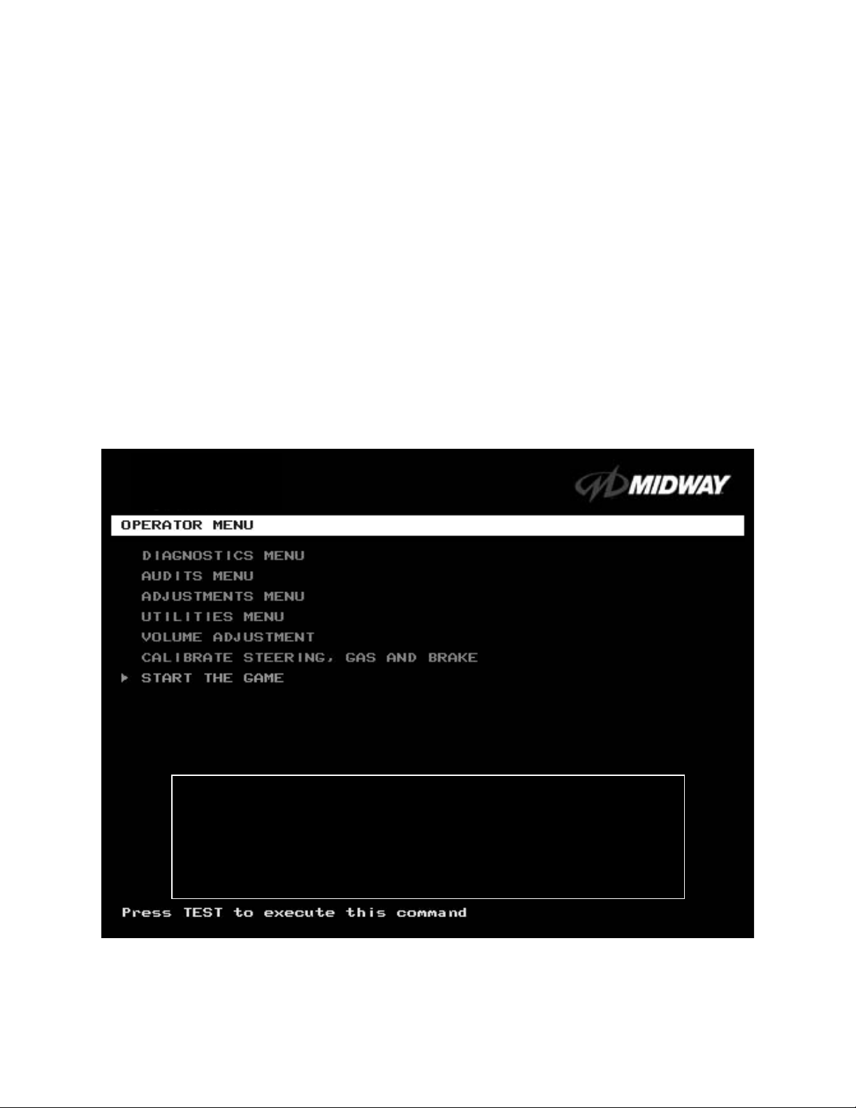
ACTIVATING THE MENU SYSTEM
Open the coin door. Find the TEST MO DE switch inside. Pres s T EST MODE to invok e the Menu System.
The game system res ponds by exiting Game Mode and entering Diagnostic Mode. T he system runs a
brief self-test, and then displays the Operator Menu. The Operator Menu is the opening screen of the
Menu System.
Game audits, adjustm ents and diagnostic s are line item s on the Oper ator Menu. Selec ting an item opens
its submenu. Every submenu presents various options that you
may act upon.
OFF ROAD THUNDER
1999 Midway Home Entertainment Inc.
All rights reserved.
OFF ROAD THUNDER is a trademark of Midway Home Entertainment Inc.
MIDWAY is a trademark of Midway Games Inc.
OPERATOR MENU
MENU LAYOUT
Menus differ, but related information tends to occupy the same screen locations.
Diagnostic, Audit & Adjustment Menu System 3-2
•
The block at the top, center of each screen displays the current menu title.
•
Data (menu items, video signals, statistics, reports, etc.) appears in the center of the screen.
•
Game-operation information appears at the top-center of the screen, between logos.
•
Messages (explanations, control functions, revision levels) display at the bottom of the screen.
MENU NAVIGATION CONTROLS
Highlight a menu line item with the middle two diagnostic buttons inside the coin door. (Press VOLUME
UP or VOLUME DOWN.) Select the option with the TEST MODE button. You can only select one
highlighted item at a time. To return the game to play, first highlight START THE GAME. Then press
TEST MODE. (This is the only menu that allows you to exit the Menu System.)
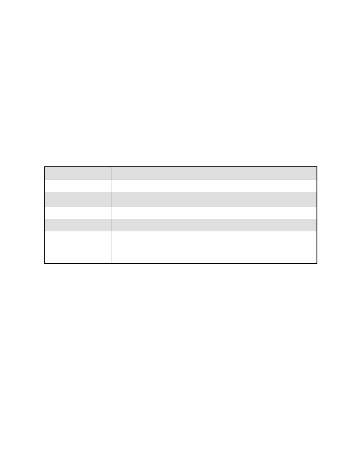
EQUIVALENT MENU NAVIGATION CONTROLS
In most cases, certain player panel buttons duplicate the functions of the diagnostic buttons. You m ay find
menu navigation easier with the player panel buttons. Here are the player panel functions within the Menu
System…
Player Panel Button Function Equivalent Diagnostic Switch
NITRO Select a menu item (None)
CHOPPER CAM
CRASH CAM Move down the menu VOLUME DOWN
SLAM CAM Move up the menu VOLUME UP
START
AUTOMATIC TESTS
Whenever you open the Menu System, the Power-On Self-Test (POST) activates. This routine runs
automatically. It can detect faults that cause gam e or Menu System malf unctions. The Self-T est usually
takes less than a minute. The test doesn’t display anything.
•
Select a menu item
•
Enter Change Mode
Various functions, including….
•
To bottom of Operator Menu
•
Back to Operator Menu
•
Cancel
SERVICE CREDITS (for some functions)
TEST MODE
Diagnostic, Audit & Adjustment Menu System 3-3
Operator Menu (continued)
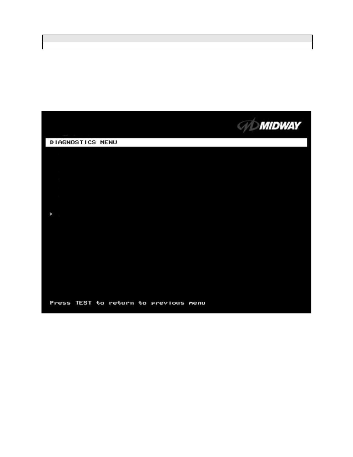
Diagnostics Menu
DIAGNOSTICS
Select DIAGNOSTICS MENU at the Operator Menu. The Diagnostics Menu helps you to verify the
electrical and electronic condition of the game.
Highlight a line item with the middle two diagnostic buttons inside the coin door. Select the option with the
TEST MODE button.
SWITCH TEST
LAMP TEST
MONITOR PATTERNS MENU
SOUND TEST
RETURN TO PREVIOUS MENU
DIAGNOSTICS MENU
Diagnostic, Audit & Adjustment Menu System 3-4
Operator Menu (continued)
Diagnostics Menu (continued)
Switch Test Menu
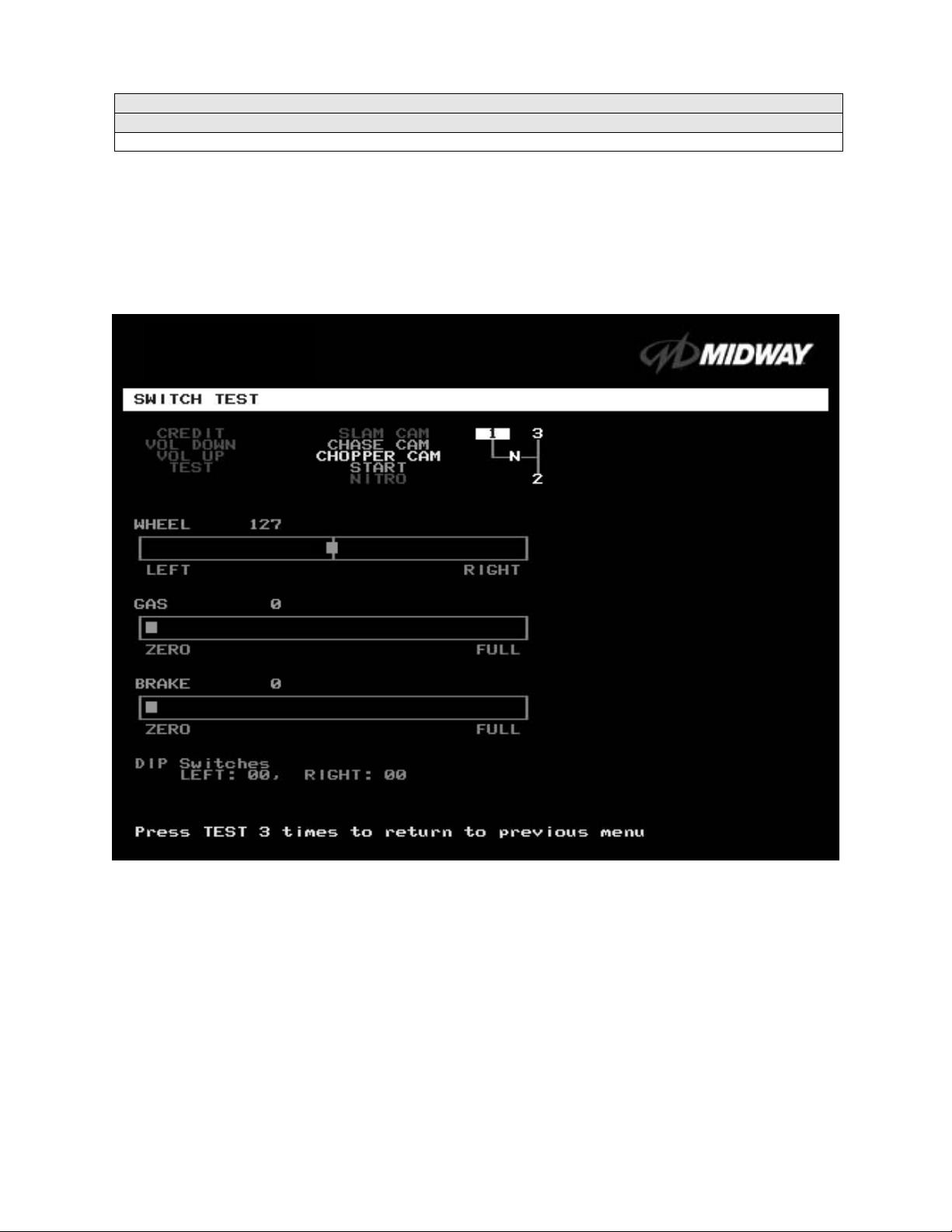
SWITCH TEST
Select SWIT CH TEST at the Diagnostics Menu. Use the Switch Test to verify crossed wires, intermittent
conditions, and stuck switches.
Operate the switch and watch the screen dis play. After completing tests,
to return to the Diagnostics Menu.
press TEST MODE three tim es
SWITCH TEST SCREEN
BUTTON TESTS
Activate each button, and the screen indicator changes state. (Gray means off and green means on.)
Release the button and the indicator returns to its previous state. A single indication on the screen should
exactly duplicate each button change.
THE WHEEL T EST
displays a wheel position number. This number varies between zero (full left) and 255 (full right).
THE GAS TEST
pedal position number. This number varies between zero (full back) and 255 (full forward).
THE BRAKE TEST
displays a pedal position number. This number varies between zero (full back) and 255 (full forward).
check player and Diagnostic switches, such as CREDIT, TEST and SLAM CAM.
indicates the steering wheel position with a moving bar on a graph. The scr een also
indicates the gas pedal position with a moving bar on a graph. The screen also displays a
indicates the brake pedal position with a moving bar on a graph. The screen also
Diagnostic, Audit & Adjustment Menu System 3-5
Operator Menu (continued)
Diagnostics Menu (continued)
Lamp Test Menu
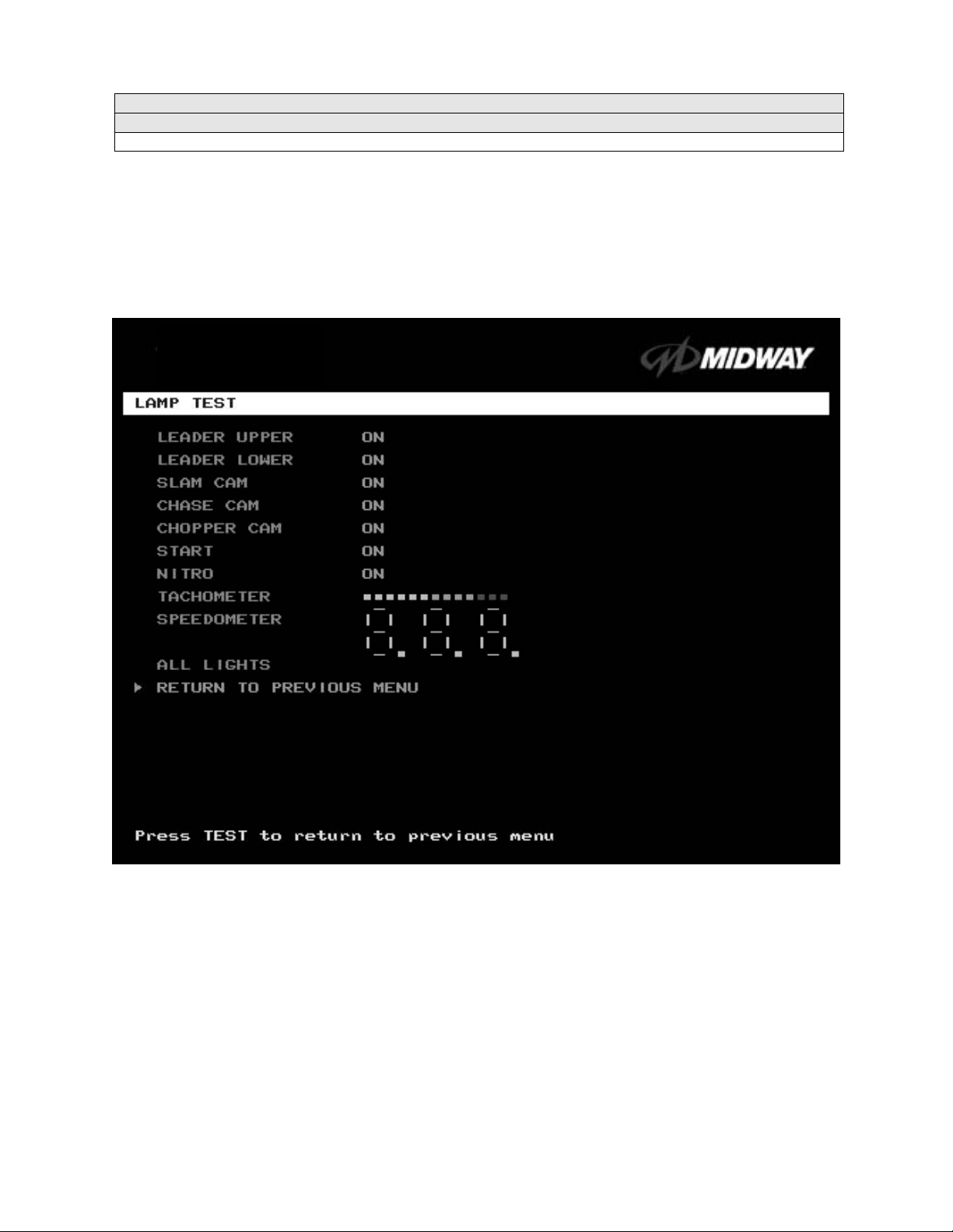
LAMP TEST
Select
lamps. Use the test to check for burned-out bulbs, faulty lamp wiring, etc.
Highlight a test with the middle two diagnostic buttons inside the coin door. Select the option with the
TEST MODE button. Pressing TEST MODE also lights the selected lamp.
LAMP TEST
at the
Diagnostics
Menu. The Lamp Test
allows you to check operation of game
LAMP TEST SCREEN
Lamp tests indicate the condition of game lam ps. T hese include lamps in the control panel and overhead
linking sign or optional header. (Unless your cabinet has header lights, the Leader Upper and Leader
Lower tests have no effect.)
For most tests, selec t a lamp name from the menu. Press T EST MODE (or CHOPPER CAM) to tur n on
the selected lamp. Press TEST MODE again to toggle the lam p off. The Tachom eter and Speedometer
tests operate slightly differently. These tests lights one LED for each press of TEST MODE. Press
START, SLAM CAM or CRASH CAM to exit. Select ALL LIGHTS to switch on all controlled lamps
simultaneously.
After completing tests, select RETURN T O PREVIOUS MENU. This action closes the Lamp T est Menu
and reopens the Diagnostics Menu.
Diagnostic, Audit & Adjustment Menu System 3-6
Operator Menu (continued)
Diagnostics Menu (continued)
Monitor Patterns Menu
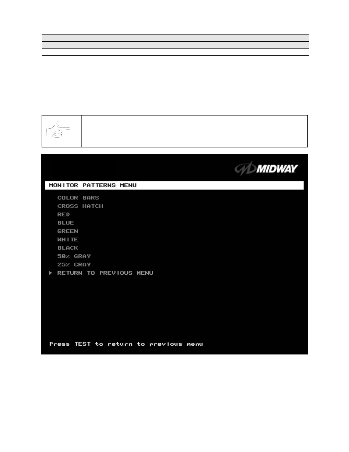
MONITOR PATTERNS TEST
Select MONITOR PATTERNS at the Diagnostics Menu. The Monitor Patterns routine provides test
screens to verify monitor performance or make adjustments.
Highlight a test with the middle two diagnostic buttons inside the coin door. Select the option with the
TEST MODE button.
NOTICE:
adjustments.
Use an industrial-grade degaussing coil before attempting monitor
MONITOR PATTERNS MENU
Color Bars
brightness and contrast. The color bars also expose defec ts in horizontal linearity. Each color bar cons ists
of 16 intensity levels. On a properly adjusted monitor, the top 15 of these levels are visible. Each bar
should appear sharp, clear, and distinct f rom bar s on either side. Incor rect adjustm ent can cause m issing
detail at the top or bottom of a bar. Bent bars indicate horizontal linearity flaws, such as pie crust,
pincushion or barrel distortion. (Correct color bar colors, left to right: Green, Red, Blue, Black, White,
paint colored stripes on the screen. Use the c olor bars to help you to check or adjus t m onitor
Diagnostic, Audit & Adjustment Menu System 3-7

Yellow, Magenta, Cyan.) Set controls as follows: 1. Adjust BRIGHTNESS and CONTRAST to minimum. 2.
Turn up BRIGHTNESS until the pixels in the black stripe begin to glow (turn dark gray). 3. Bring up the
CONTRAST control until you can see 15 bars. Then increase the contrast until you can’t distinguish a
difference between the top two bars.
Crosshatch Patterns
check or adjust several monitor parameters: These parameters include convergence, linearity, active
viewing area and dynamic focus. The grid and the dots should be all white in color, with no fringes or
parallel images. The lines should be straight and the dots round. For more detail on these adjustm ents,
consult service literature from the monitor manufacturer.
Color Screen
tests help you to check or adjust monitor intensity, black level, blanking and color purity. Each screen
should be absolutely uniform from top to bottom and side to side. No retrace lines or noise should be
visible. Color Screens may not hold their uniformity if the monitor degaussing circuit is defective.
If tests indicate a need for adjustment, use contr ols on the Monitor Remote Adjustment Board. You can
make other adjustments from the back of the monitor.
White, Gray, and Black Screens
monochrome screens help you to check or adjust monitor convergence, purity, contrast and intensity.
These screens also simplify black level and color gun control settings. The screens should be uniform with
no color tints or distortion. No retrace lines or noise should be visible.
If tests indicate a need for adjustment, use controls on the Monitor Remote Adjustment Board.
tests fill the screen with 100% of the c hosen color at normal intensity. The Color Screen
consist of an on-screen gr id and a series of dots. Cr osshatch Patterns help you to
fill the screen with black, gray or white at various intensities. T hese
Diagnostic, Audit & Adjustment Menu System 3-8
Operator Menu (continued)
Diagnostics Menu (continued)
Sound Test Menu
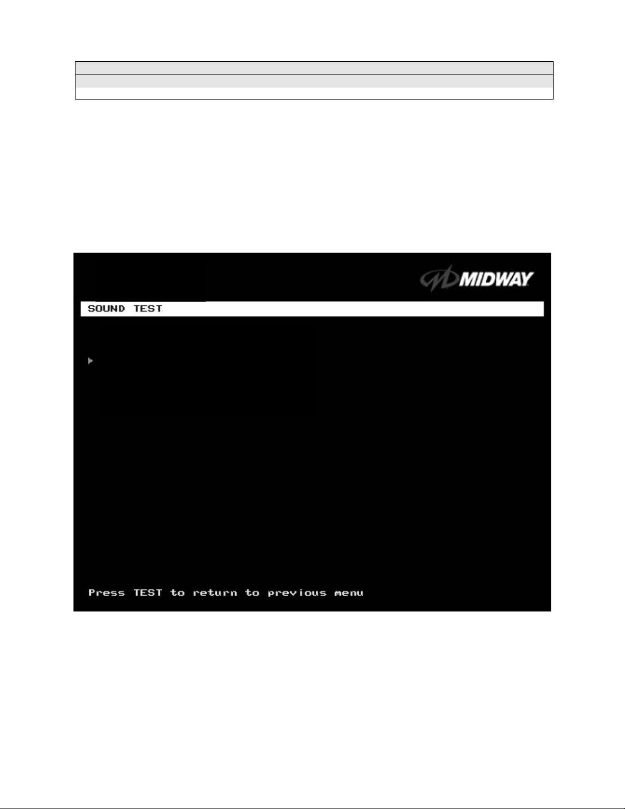
SOUND TEST
Select SOUND TEST at the Diagnostics Menu. The Sound Test verifies the operation of the sound
hardware and speakers. Use the Sound Test to find crossed connections, incorrect phase, rattles,
vibration, distortion, etc. The Sound Test
Increase the master volume level before beginning this test.
Highlight a test with the middle two diagnostic buttons inside the coin door. Select the option with the
TEST MODE button. Selecting also activates a sound tone. The tone continues to play until you once
again press TEST MODE.
BEEP FRONT SPEAKER
BEEP RIGHT SPEAKER
RETURN TO PREVIOUS MENU
screen reports information, but doesn’t permit changes.
SOUND TEST SCREEN
After choosing a speaker nam e, listen to the audio tone from that speaker. Only the specified speaker
should produce sound. The other speakers should remain silent.
To exit the Sound Test Menu, highlight RETURN TO PREVIOUS MENU. Then press TEST MODE.
Diagnostic, Audit & Adjustment Menu System 3-9
Operator Menu (continued)
Audits Menu
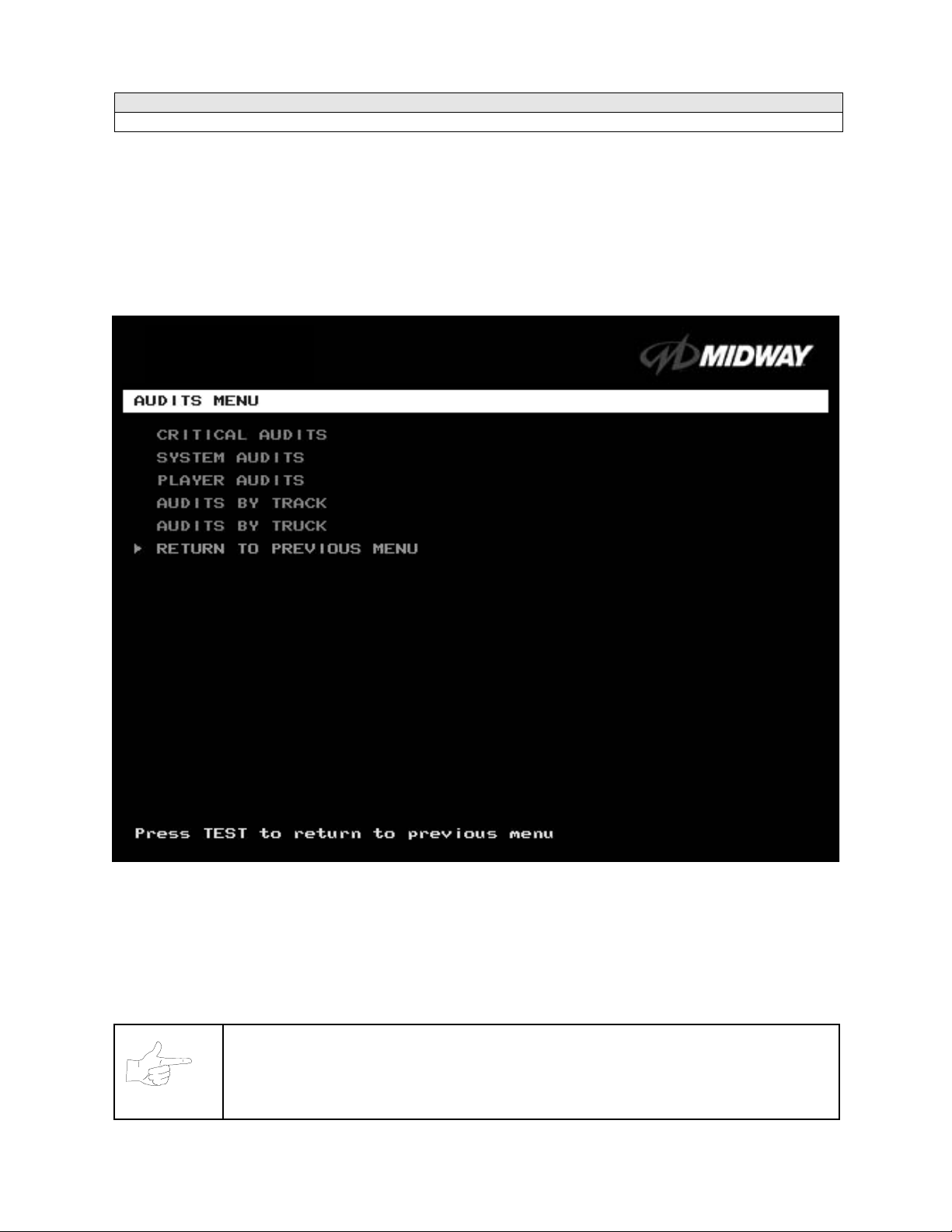
AUDITS MENU
Select AUDITS MENU at the Operator Menu. The Audits Menu permits you to review game play statistics.
Additional menus provide detailed reports f or each player position on game starts, ends, cabinet abuse,
fault conditions, etc.
Highlight a line item with the middle two diagnostic buttons inside the coin door. Select the option with the
TEST MODE button.
GAME AUDITS MENU
Use the auditing information to help you to keep records of the game’s popular ity and earnings. You may
also analyze favorite tracks, most frequently used vehicles, and other statistics. These screens report
information, but don’t permit changes.
Examine and record all game audit values before doing service or making repairs on this game.
NOTICE:
Take care when clearing audit information. You can’t restore c leared data. If your audit
data is important to you, back it up before proceeding. Us e the OPT ION SAVE AUDITS
TO FLOPPY DISK on the Utilities Menu. To clear audits, use the Utilities Menu.
Diagnostic, Audit & Adjustment Menu System 3-10

Operator Menu (continued)
Audits Menu (continued)
Critical Audits Menu
CRITICAL AUDITS
Select CRITICAL AUDITS at the Audits Menu. T he Critical Audits Menu repor ts gener al inf orm ation about
coin counts and game use.
CRITICAL AUDITS
CREDITS 0
PARTIAL CREDITS 0
BONUS CREDITS 0
GAME IN PROGRESS DURING LAST SHUTDOWN: NO
TIME SINCE LAST POWER-ON: 2 DAYS, 20:36:35
This menu reports information, but doesn’t permit changes
.
CRITICAL AUDITS MENU
CREDITS
information on game operation.
BONUS CREDITS.
GAME IN PROGRESS DURING LAST SHUTDOWN.
entered Diagnostic Mode? This function answers the question.
TIME SINCE LAST POWER-ON. This function
starts counting
PARTIAL CREDITS
and
A running total of bonus credits that the video game awarded to players.
whenever you switch off the video game machine.
Diagnostic, Audit & Adjustment Menu System 3-11
permit you to assess currency collection. The other items present
measures the period between power-ups. The clock
Was the machine in Game-Play Mode when it

Operator Menu (continued)
Audits Menu (continued)
System Audits
SYSTEM AUDITS
Select SYSTEM AUDITS at the Audits Menu. The System Audits Menu reports general infor mation about
coin counts and game use. Coin Audits is a read-only screen.
To exit, press TEST MODE.
SYSTEM AUDITS
POWER ON TIME 0:00:00
RACE TIME 0:00:00
LINKED RACE TIME 0:00:00
POWER ON TIME SINCE LAST RESET 0:00:00
RACE TIME SINCE LAST RESET 0:00:00
NUMBER OF RESETS 0
NUMBER OF WATCHDOG RESETS 0
NUMBER OF GAMES SINCE WATCHDOG RESET 0
NUMBER OF GAMES SINCE PREVIOUS WATCHDOG RESET 0
NUMBER OF DEMOS SINCE LAST GAME 0
NUMBER OF LOST PLAYERS DURING A RACE 0
NUMBER OF LOST LINKS DURING A RACE 0
NUMBER OF RE-LINKS 0
NUMBER FOR OUT OF SYNC GAMES 0
LEFT COIN COUNT 0
RIGHT COIN COUNT 0
FOURTH COIN COUNT 0
BILL COUNT 0
SERVICE CREDITS 0
FREE CREDITS 0
SYSTEM AUDITS MENU
The System Audits Menu reports total quantities of coins, bills or credits collected by each active device.
The menu does not calculate the value of the collected currency.
This menu reports information, but does not permit you to make changes. To reset the coin, bill, and credit
counters to zero, use the Clear Audits menu.
We rec ommend that you examine and record audit infor mation before you make changes. Once you’ve
cleared the counters, you can’t retrieve the previous data from the system.
THE COIN COUNT AND BILL COUNT
present information on game operation.
RESET, LINK, AND SYNC
conditions that adversely affect game play.
statistics are measures of the game software’s ability to recover from
Diagnostic, Audit & Adjustment Menu System 3-12
items help you to assess currency collection. The other items

Operator Menu (continued)
Audits Menu (continued)
Player Audits Menu
PLAYER AUDITS
Select PLAYER AUDITS at the Audits Menu. The Player Audits Menu displays additional information
about player statistics and ability. This information as sis ts you in understanding game use and prof itability.
Player Audits is a read-only screen.
PLAYER A UDITS MENU
GAMES PLAYED.
CONTINUES.
FREE GAMES WON
Adjustments Menu for the bonus and award options settings.
STARTS.
FREE GAMES %.
TIME EXPIRES.
DID NOT FINISH.
FINISHES.
TWO, THREE AND FOUR-PLAYER RACES
Number of games that players started.
Number of completed games.
Total number of games that players played on this machine.
Total number of games on this machine that players paid to continue.
remains at zero if you turn off the bonus and award options. Refer to the General
Proportion of games that were free, expressed as a percentage.
Number of times that time expired before a player completed the game.
Number of incomplete games.
remain at zero if no other games are linked to this one.
Diagnostic, Audit & Adjustment Menu System 3-13

Operator Menu (continued)
Audits Menu (continued)
Track Audits Menu
TRACK AUDITS
Select TRACK AUDITS at the Audits Menu. T he Track Audits Menu includes
player choices and ability.
TRUCK SELECTED WINNER
Hyena 0 0
Outlaw 0 0
General 0 0
Thrasher 0 0
Silver Streak 0 0
Snake Eyes 0 0
Chieftan 0 0
Bad Omen 0 0
Nitro Ninja 0 0
Wilcat 0 0
Dust Devil 0 0
Stinger 0 0
This is a read-only menu.
specific information about
TYPICAL TRACK AUDITS
MENU
These audits cover several screen pages. The name of the track appears at the top of the page. Press the
VOLUME UP or VOLUME DOWN buttons to move through these pages
.
Diagnostic, Audit & Adjustment Menu System 3-14

Operator Menu (continued)
Audits Menu (continued)
Truck Audits Menu
TRUCK AUDITS
Select TRUCK AUDITS at the Audits Menu. The T ruck Audits Menu gives you
player choices and ability.
Menu software includes several pages of audits. The name of the vehicle appears at the top of each menu
page. Press the VOLUME UP or VOLUME DOWN buttons to navigate through these pages
This is a read-only menu.
specific information about
.
TYPICAL AUDITS BY TRUCK SCREEN
Diagnostic, Audit & Adjustment Menu System 3-15

Operator Menu (continued)
Adjustments Menu
ADJUSTMENTS MENU
Select ADJUSTMENTS MENU at the Operator Menu. The Adjus tm ents Menu allows you to set game and
player variables. Use these screens to optimize game performance and earnings.
Highlight an option with the middle two diagnostic buttons inside the coin door. Select the option with the
TEST MODE button.
GENERAL ADJUSTMENTS MENU
LINKED –PLAY ADJUSTMENTS MENU
TRACK DIFFICULTY ADJUSTMENTS MENU
PRICING MENU
VOLUME ADJUSTMENT
FORCE FEEDBACK ADJUSTMENT
CALIBRATE STEERING, GAS AND BRAKE
SET TIME AND DATE
RETURN TO PREVIOUS MENU
ADJUSTMENTS MENU
Diagnostic, Audit & Adjustment Menu System 3-16

Operator Menu (continued)
Adjustments Menu (continued)
General Adjustments Menu
GENERAL ADJUSTMENTS MENU
Select GENERAL ADJUSTMENTS MENU at the Adj ustments Menu. At the G eneral Adjustments Menu,
you set the cabinet type, game display and measurement system. General Adjustments Menu options
also control the cost and type of play.
Highlight an option with the middle two diagnostic buttons inside the coin door. Press TEST MODE to
enter Change Mode. Use the diagnostic switches to change the variable. Then press TEST MODE to save
changes and exit the variable.
GENERAL ADJUSTMENTS MENU
FREE PLAY
determines whether the game acc epts money for play, or allows operation without charge.
For free play, turn this option on. For paid play, turn this option off (the factory default).
FREE RACE FOR 1
ST
permits a free gam e for players who finish in firs t place. To award a free r ace to a
first-place finisher, tur n this option on. To eliminate the free race award, tur n this option off. The factory
default is on.
ST
FREE RACE FOR 1
(LINKED).
This feature awards a free game to the first place finisher among human
players. The feature only operates when a minimum number of players join in. To award a free race to a
first-place finisher, turn this option on. To eliminate the free race award, turn this option off. Available
settings include 2, 3 or 4 players, or off. The factory default setting is off.
Diagnostic, Audit & Adjustment Menu System 3-17

SHOW MILES PER HOUR
in kilometers per hour, turn SHOW MILES PER HOUR off. To display speed in miles per hour, turn
SHOW MILES PER HOUR on (the factory default).
sets the measurem ent system for dis play on gam e s creens . T o dis play speed
ADULT MODE.
disable Adult Mode, the cheerleaders appear in more conservative attire. The default setting is on.
When you enable Adult Mode, the glamorous cheerleaders appear in bikinis. W hen you
Diagnostic, Audit & Adjustment Menu System 3-18

Operator Menu (continued)
Adjustments Menu (continued)
Linked-Play Adjustments Menu
LINKED PLAY ADJUSTMENTS MENU
Select LINKED PLAY ADJUSTMENTS MENU at the Adjustm ents Menu.
The Linked Play Adjustments
Menu allows you to set the game cabinet network identity. After you cable the linked cabinets, use this
menu to set up linked play.
Highlight an option with the middle two diagnostic buttons inside the coin door. Press TEST MODE to
enter Change Mode. Use the diagnostic switches to change the variable. Then press TEST MODE to save
changes and exit the variable.
FREE PLAY
LINKED PLAY ENABLED
UNIT ID (1-4): 1
LINKED-PLAY ADJUSTMENTS MENU
Before proceeding, bring up the Linked Play Adjustments Menu on all linked cabinets.
LINKED PLAY.
After you link a cabinet to other games, turn on LINKED PLAY. Now game electronics can
communicate with other cabinets. To prohibit linked play, turn off the feature. The factory default is off.
UNIT ID
determines the gam e’s address. Each link ed game must have a unique num ber. Never use the
same address for two cabinets. Sequence isn’t important. The factory default ID is 1.
REINITIALIZE.
After selecting the ID, exit the Menu System. Shut down each linked cabinet for one
minute. (Leave the computers switched on.) Then restore power to all cabinets. The cabinets should
initialize in Linked Mode. Verify linked operation by playing some linked games.
Diagnostic, Audit & Adjustment Menu System 3-19

Operator Menu (continued)
Adjustments Menu (continued)
Track Difficulty Adjustments Menu
TRACK DIFFICULTY ADJUSTMENTS MENU
Select TRACK DIFFICULTY ADJUSTMENTS MENU at the Adjustments Menu. F rom the Track Difficulty
Adjustments Menu, you set how much skill players need to complete races.
Highlight an option with the middle two diagnostic buttons inside the coin door. Press TEST MODE to
enter Change Mode. Use the diagnostic switches to change the variable. Then press TEST MODE to save
changes and exit the variable.
TRACK DIFFICULTY ADJUSTMENTS MENU
LIMIT FREE RACES TO
monopolizing a cabinet. The range is 1 to 100%. The factory default is 10%.
BONUS START TIME.
players. The factory default is zero seconds.
BONUS CHECKPOINT TIME.
checkpoints. The factory default is zero seconds.
ADJUST TRACK DIFFICULTIES MENU
(LFRT) is the award cutoff point. LFRT prevents expert players from
You can use this feature to award several seconds of extra time to starting
Use this feature to award several seconds of extra time as players pass
allows you to modify the level of challenge that each track poses.
Diagnostic, Audit & Adjustment Menu System 3-20

Operator Menu (continued)
Adjustments Menu (continued)
Track Difficulty Adjustments Menu (continued)
Adjust Track Difficulties Menu
ADJUST TRACK DIFFICULTIES MENU
Select ADJUST TRACK DIFFICULTIES MENU at the T rac k Diff iculty Adjustm ents Menu. From the Adjust
Track Diff iculties Menu, you modify the level of challenge that each track poses. You can also increas e or
reduce starting and checkpoint bonus time. Difficulty and bonus default values are all zero.
Highlight an option with the middle two diagnostic buttons inside the coin door. Press TEST MODE to
enter Change Mode. Use the diagnostic switches to change the variable. Press TEST MODE to save
changes and exit the variable. Or press TEST CREDITS to cancel changes and exit the variable.
You’ll notice that each option line has three columns of figures to c hange. The program lets you edit each
column in turn. First you modify BASE DIFFICULTY, then START BONUS, and last, CHECKPOINT
BONUS.
Tunnel Vision 0 0 0
Over ‘N’ Under 0 0 0
Air Time 0 0 0
High Octane 0 0 0
Carnie of Chaos 0 0 0
Cliffhanger 0 0 0
Double Barrel 0 0 0
Alpine Air 0 0 0
Tunnel Vision Mirror 0 0 0
Over ‘N’ Under Mirror 0 0 0
Airtime Mirror 0 0 0
High Octane Mirror 0 0 0
Carnie of Chaos Mirror 0 0 0
Cliffhanger Mirror 0 0 0
Double Barrel Mirror 0 0 0
Alpine Air Mirror 0 0 0
ADJUST TRACK DIFFICULTIES MENU
Diagnostic, Audit & Adjustment Menu System 3-21

Operator Menu (continued)
Adjustments Menu (continued)
Pricing Menu
PRICING MENU
Select PRICING MENU at the Adjustments Menu.
standard and custom currency combinations. The factory default is USA1.
Highlight an option with the middle two diagnostic buttons inside the coin door. Press TEST MODE to
enter Change Mode. Use the diagnostic switches to change the variable. Then press TEST MODE to save
changes and exit the variable. Turning on Free Play disables Pricing Menu settings.
The Pricing Menu contains options for selecting
PRICING MENU
SELECT CUSTOM PRICING
your own pricing schemes. This menu permits changes to default values.
SELECT STANDARD PRICING
permits changes to default values.
RESET TO DEF AULTS
all current values at once.
allows you to set coin and credit options manually. Use this option to create
allows you to select from several ready-made price schem es This m enu
returns the price settings to fa ctory default values. This menu perm its changing
Diagnostic, Audit & Adjustment Menu System 3-22

Operator Menu (continued)
Adjustments Menu (continued)
Pricing Menu (continued)
Select Custom Pricing Menu
SELECT CUSTOM PRICING MENU
Choose SELECT CUSTOM PRICING at the Pricing Menu. The Selec t Custom Pricing Menu per mits you
to program and use your own pricing table. You can save sever al pricing schemes and chose between
them as desired.
Highlight an option with the middle two diagnostic buttons inside the coin door. Press TEST MODE to
enter Change Mode. Use the diagnostic switches to change the variable. Then press TEST MODE to save
changes and exit the variable.
TYPICAL SELECT CUSTOM PRICING MENU
The Custom Pricing Menu employs the same terms that appear on the Current Pricing Table. See the
table below for definitions of these terms.
Diagnostic, Audit & Adjustment Menu System 3-23

PRICING MENU TERMS
SCREEN TERM DISCUSSION
Slot Units;
Bill Validator (DBV)
Units
Units per Credit
Units per Bonus
Minimum Units
Credits to Start
Credits to Continue
Max Credits
Coins per Bill
Cyber-currency. This adjustment assigns a number of “units” to each coin mechanism
or bill acceptor. For instance, if a quarter buys 1 unit, then $1 buys 4 units. (See Coins
per Bill.) You insert a coin into a 1-unit coin acceptor. The system, due to its
programming, knows that your coin is worth one unit.
How many units equal one credit. (Units buy credit, the price of one game.)
Units awarded when a player earns a bonus.
Until this many units accumulate, the system awards no credits.
Number of games a player must purchase to begin play.
Number of games a player must purchase to resume play.
Limits the number of credits that the game will accept.
How many coins one bill is worth.
BASIC CUSTOM PRICING.
Custom pricing creates an imaginary currency exchange. In this currency
exchange, the coins of the realm ar e “units.” T hink of units as a type of cyber-currency, useful only within
the game software. By inserting coins, you purchase units.
Since units are only negotiable within game software, the system stores your units for you. When the
system receives enough units, it buys a game for you. The price of a gam e is one “credit.” You can think
of credits as a second form of cyber-currency.
Even though you’ve now bought one game, you may not be able to begin playing. In many pricing
schemes, you must buy two or more cr edits to begin play. The idea here is som ething like a minimum
order of goods at a store. That is , the operator can “shrink-wrap” two or more games in a package. You
can’t play unless you buy the entire package.
1 / 25¢ COIN; 1 CREDIT TO START
•
.
In a simple, quarter pricing scheme, the player inserts one coin to buy
one unit. The system exchanges that unit f or one credit. If CREDITS T O START contains the value one,
then play commences. A dollar bill buys four units.
Left Slot Units Validator Units Units / Credit Credits to Start Coins / Bill
14114
1 / 3 X 25¢; 2 CREDITS TO START.
•
Again, assuming quarter slots, here’s one way to implement 75¢
pricing… In this scheme, each coin that the player inserts buys one unit. The system ex changes three
units for one credit. CREDITS TO START contains the value two. To play, the player must pay for two
credits. In this scheme, a dollar buys four units.
Left Slot Units Validator Units Units / Credit Credits to Start Coins / Bill
14324
2 / 1 COIN; 6 CREDITS TO START
•
.
Now let’s consider a more unusual pricing scheme. Here, the player
can buy two units with one coin. The system exchanges each of these units for one credit. Notice that
CREDITS TO START contains the value six. To play, the player must insert two m ore coins to pay for six
credits. Also notice that if the player pays with a bill, the system throws in an extra unit.
Left Slot Units Validator Units Units / Credit Credits to Start Coins / Bill
29164
Diagnostic, Audit & Adjustment Menu System 3-24

Operator Menu (continued)
Adjustments Menu (continued)
Pricing Menu (continued)
Select Standard Pricing Continent Menu
SELECT STANDA RD PRICING CONTINENT MENU
Choose SELECT STANDARD PRICING at the Pricing Menu.
Menu allows you to choose the continent that you are operating in.
Highlight a line item with the middle two diagnostic buttons inside the coin door. Select the option with the
TEST MODE button.
The Select Standard Pricing Continent
STANDARD PRICING MENU
Diagnostic, Audit & Adjustment Menu System 3-25

Operator Menu (continued)
Adjustments Menu (continued)
Pricing Menu (continued)
Select Standard Pricing Continent Menu
Select Standard Pricing Country for North America Menu
SELECT STANDARD PRICING COUNTRY FOR NORTH AMERICA MENU
Choose a continent (NORTH AMERICA, f or ex ample) at the Select Standard Pricing Continent Menu.
Select Standard Pricing Country for North America Menu contains options for selecting s tandard curr ency
combinations. You may use standard pricing schemes as-is, or customize them.
Highlight a line item with the middle two diagnostic buttons inside the coin door. Select the option with the
TEST MODE button.
The
TYPICAL SELECT STANDARD PRICING FOR NORTH AMERICA MENU
Diagnostic, Audit & Adjustment Menu System 3-26

Operator Menu (continued)
Adjustments Menu (continued)
Pricing Menu (continued)
Select Standard Pricing Continent Menu (continued)
Select Standard Pricing Country for North America Menu (cont’d)
SELECT STANDA RD PRICING MENU
Select Standard Pricing Table for USA Menu (cont’d)
Suppose that you want to set U.S. pricing. Choose USA at the menu entitled
Country for North America. This menu contains options for selecting standard U.S. currency combinations.
Highlight an option with the middle two diagnostic buttons inside the coin door. Press TEST MODE to
enter Change Mode. Use the diagnostic switches to change the variable. Then press TEST MODE to save
changes and exit the variable.
Select Standard Pricing
TYPICAL VIEW CURRENT PRICING DISPLAY
Diagnostic, Audit & Adjustment Menu System 3-27

STANDARD PRICING TABLE
NAME START CONTINUE CREDITS/COIN COIN 1 COIN 2 COIN 3 COIN4 BILL
ANTILLES 2 2 1/25¢, 4/1G .25¢ 1G
AUSTRALIA 1 2 2 1/3X20¢, 2/$1.00 .20¢ $1.00
AUSTRALIA 2 2 2 1/5X20¢, 1/$1.00 .20¢ $1.00
AUSTRIA 1 2 2 1/5Sch, 2/10Sch 5 Sch 10 Sch
AUSTRIA 2 2 2 1/2X5Sch, 3/2X10Sch 5 Sch 10 Sch
BELGIUM 1 2 2 1/20BF 20BF 20BF
BELGIUM 2 2 2 3/20BF 20BF 20BF
BELGIUM 3 2 2 2/20BF 20BF 20BF
BELGIUM ECA 2 2 1/20BF 50BF 20BF 5BF
CANADA 1 2 2 1 / 2 x 25¢, 3 / $1 25¢ 25¢
CANADA 2 2 2 1 / 2 x 25¢, 3 / $1 25¢ $1.00
CANADA 3 2 2 3 / $1.00, 6 / $2.00 $1.00 $2.00
CANADA ECA 2 2 1 / 2 x 25¢, 3 / $1 25¢ $1.00 $2.00
DENMARK 2 2 3/5DKr, 7/10DKr 5DKr 10DKr
FINLAND 2 2 1/1Fmk 1Fmk 5Fmk
FRANCE 1 2 2 2/5Fr, 5/10Fr 5Fr 10Fr
FRANCE 2 2 1 2/5Fr, 4/10Fr 5Fr 10Fr
FRANCE 3 2 1 1/5Fr, 3/10Fr 5Fr 10Fr
FRANCE 4 2 1 1/5Fr, 2/10Fr 5Fr 10Fr
FRANCE 5 2 1 2/5Fr, 5/10Fr, 11/2 X 10Fr 5Fr 10Fr
FRANCE 6 2 1 2/5Fr, 4/10Fr, 9/2 X 10Fr 5Fr 10Fr
FRANCE 7 2 1 1/5Fr, 3/10Fr, 7/2 X 10Fr 5Fr 10Fr
FRANCE 8 2 1 1/5Fr, 2/10Fr, 5/2 X 10Fr 5Fr 10Fr
FRANCE 9 2 1 1/3 X 1Fr, 2/5Fr 1Fr 5Fr
FRANCE 10 2 1 1/2 X 1Fr, 3/5Fr 1Fr 5Fr
FRANCE 11 2 1 1/3 X 1Fr, 2/5Fr, 5/2 X 5Fr 1Fr 5Fr
FRANCE 12 2 1 1/2 X 1Fr, 3/5Fr, 7/2 X 5Fr 1Fr 5Fr
FRANCE ECA 1 1 1 2/5Fr, 5/10Fr 1Fr 5Fr 10Fr 20Fr
FRANCE ECA 2 1 1 2/5Fr, 4/10Fr 1Fr 5Fr 10Fr 20Fr
FRANCE ECA 3 1 1 1/5Fr, 3/10Fr 1Fr 5Fr 10Fr 20Fr
FRANCE ECA 4 1 1 1/5Fr, 2/10Fr 1Fr 5Fr 10Fr 20Fr
FRANCE ECA 5 1 1 2/5Fr, 5/10Fr, 11/2 X 10Fr 1Fr 5Fr 10Fr 20Fr
FRANCE ECA 6 1 1 2/5Fr, 4/10Fr, 9/2 X 10Fr 1Fr 5Fr 10Fr 20Fr
FRANCE ECA 7 1 1 1/5Fr, 3/10Fr, 7/2 X 10Fr 1Fr 5Fr 10Fr 20Fr
FRANCE ECA 8 1 1 1/5Fr, 2/10Fr, 5/2 X 10Fr 1Fr 5Fr 10Fr 20Fr
FRANCE ECA 9 1 1 1/3 X 1Fr, 2/5Fr 1Fr 5Fr 10Fr 20Fr
FRANCE ECA 10 1 1 1/2 X 1Fr, 3/5Fr 1Fr 5Fr 10Fr 20Fr
FRANCE ECA 11 1 1 1/3 X 1Fr, 2/5Fr, 5/10Fr 1Fr 5Fr 10Fr 20Fr
FRANCE ECA 12 1 1 1/2 X 1Fr, 3/5Fr, 7/10Fr 1Fr 5Fr 10Fr 20Fr
FRANCE ECA 13 1 1 1/10Fr, 2/20Fr, 4/30Fr 1Fr 5Fr 10Fr 20Fr
FREE PLAY -- -- -- None None None None None
GERMANY 1 2 2 1/1DM, 6/5DM 1DM 5DM
GERMANY 2 2 1 1/1DM, 7/5DM 1DM 5DM
GERMANY 3 2 1 1/1DM, 8/5DM 1DM 5DM
GERMANY 4 2 1 1/1DM, 5/5DM 1DM 5DM
GERMANY 5 2 1 1/1DM, 6/5DM 1DM 5DM
GERMANY ECA 1 2 2 1/1DM, 2/2DM, 6/5DM 1DM 2DM 5DM
GERMANY ECA 2 2 1 1/1DM, 2/2DM, 6/5DM 1DM 2DM 5DM
GERMANY ECA 3 1 1 1/1DM, 2/2DM, 6/5DM 1DM 2DM 5DM
HUNGARY 2 2 1/2X10Ft, 3/2X20Ft 10Ft 20Ft
ITALY 2 2 1/500LIt 500LIt 500LIt
JAPAN 1 2 2 1/100Yen 100 100
JAPAN 2 2 2 2/100Yen 100 100
NETHERLANDS 2 2 1/1HFI, 3/2.5HFI 1HFI 2.5HFI
NEW ZEALAND 1 1 1 1/$1 $1 $2
NEW ZEALAND 2 1 1 2/$1 $1 $2
NORWAY 2 2 3/5NKr, 6/10NKr 5NKr 10NKr
SPAIN 1 2
SPAIN 2 2 2 1/100Pta, 5/500Pta 100Pta 500Pta
SWEDEN 2 2 1/3X1SKr, 2/ 5SKr 1SKr 5SKr
SWITZERLAND 1 2 2 1/1SFr, 6/5SFr 1SFr 5SFr
SWITZERLAND 2 2 2 1/1SFr, 7/5SFr 1SFr 5SFr
SWITZERLAND 3 2 2 1/1SFr, 8/5SFr 1SFr 5SFr
2 1/100Pta, 6/500Pta
100Pta 500Pta
(Table continues on next page)
Diagnostic, Audit & Adjustment Menu System 3-28

STANDARD PRICING TABLE, continued
NAME START CONTINUE CREDITS/COIN COIN 1 COIN 2 COIN 3 COIN4 BILL
UK ECA 1 1 1 1/50p, 3/£1.00 £1.00 50p 20p 10p £2.00
UK ECA 2 1 1 1/50p, 2/£1.00 £1.00 50p 20p 10p £2.00
UK ECA 3 1 1 1/30p, 2/50p, 5/£1.00 £1.00 50p 20p 10p £2.00
UK 4 1 1 1/50p, 3/£1.00 £1.00 50p
UK 5 1 1 1/50p, 2/£1.00 £1.00 50p
UK ECA 6 1 1 1/30p, 2/50p, 4/£1.00 £1.00 50p 20p 10p £2.00
UK ECA 7 1 1 3/£1.00 £1.00 50p 20p 10p £2.00
UK ECA 8 1 1 1/50p, 2/£1.00, 4/£2.00 £1.00 50p 20p 10p £2.00
USA1 2 2 1/25¢ 25¢ 25¢ $1.00
USA2 2 1 1/25¢ 25¢ 25¢ $1.00
USA3 1 1 1/25¢ 25¢ 25¢ $1.00
USA4 1 1 1/50¢, 3/$1.00 25¢ 25¢ $1.00
USA5 2 1 1/50¢, 4/$1.00 25¢ 25¢ $1.00
USA6 1 1 1/50¢ 25¢ 25¢ $1.00
USA7 1 1 1/50¢, 3/$1.00 25¢ 25¢ $1.00
USA8 2 2 1/50¢, 4/$1.00 25¢ 25¢ $1.00
USA9 3 2 1/25¢, 4/$1.00 25¢ 25¢ $1.00
USA10 3 3 1/25¢, 4/$1.00 25¢ 25¢ $1.00
USA11 4 2 1/25¢, 4/$1.00 25¢ 25¢ $1.00
USA12 4 3 1/25¢, 4/$1.00 25¢ 25¢ $1.00
USA13 4 4 1/25¢, 4/$1.00 25¢ 25¢ $1.00
USA ECA 3 3 1/25¢, 4/$1.00 $1.00 25¢ 10¢ 05¢ $1.00
Diagnostic, Audit & Adjustment Menu System 3-29

Operator Menu (continued)
Adjustments Menu (continued)
Volume Adjustment Menu
VOLUME ADJUSTMENT MENU
Select VOLUME ADJUSTMENT at the Adjustments Menu.
Operator Menu.) The Volume Adjustment Menu allows you to adjust relative sound loudness levels.
Highlight an option with the middle two diagnostic buttons inside the coin door. Press TEST MODE to
enter Change Mode. Use the diagnostic switches to change the variable. Then press TEST MODE to save
changes and exit the variable.
(You can also access this menu from the
VOLUME ADJUSTMENT MENU
NOTICE:
alter Attract sounds in relation to norm al game sound. For example, suppose that you
set Attract Mode volume to 50%. Then Attract Mode sounds are half as loud as normal
game sounds.
NOTICE:
fully test speakers. Restore Master Volume to its previous level before returning to
Game-Over Mode.
The Master Volume s etting affects all other volum e adjustm ents. You can still
Check the Master Volume setting before testing. Incr ease Master Volume to
Diagnostic, Audit & Adjustment Menu System 3-30

MASTER VOLUM E
other sound settings. The range is 1 to 100%. The factory default is 60%.
sets the overall volume level during game play. This value s imultaneously affects all
ATTRACT VOLUME
Attract Mode sound level is independent of game audio levels. The Attract Volum e range is 1 to 100%.
The factory default is 50%.
MINIMUM VOLUME
default is 20%.
To exit the Volume Adjustment Menu, highlight RETURN TO PREVIOUS MENU. Then press TEST
MODE.
adjusts the Attract Mode sound level only when you turn on Attract Mode. The
sets the quietest sound level during game play. The range is 1 to 100%. T he fac tory
Diagnostic, Audit & Adjustment Menu System 3-31

Operator Menu (continued)
Adjustments Menu (continued)
Force Feedback Adjustment Menu
FORCE FEEDBACK ADJUSTMENT
Select FORCE FEEDBACK ADJUSTMENT MENU at the Adjustments Menu. The Force Feedback
Adjustment Menu allows you to alter the intensity of steering wheel feedback.
Highlight an option with the middle two diagnostic buttons inside the coin door. Press TEST MODE to
enter Change Mode. Use the diagnostic switches to change the variable. Then press TEST MODE to save
changes and exit the variable.
FORCE FEEDBACK ADJUSTMENT MENU
THE INTENSITY ADJUSTMENT
setting is 60%. If players have superior upper body strength, apply greater force. Younger players may be
more comfortable with smaller force settings.
THE FORCE FEEDBACK CENTER TEST
this option and move the steering wheel to any position. As soon as you release the wheel, it must
automatically return to its center position. If it doesn’t, then the vehicle won’t respond properly.
Diagnostic, Audit & Adjustment Menu System 3-32
ranges from 0% (m inimum) to 100% (maximum ). The factory default
checks operation of s teering wheel motor drive circuits . Select

Operator Menu (continued)
Adjustments Menu (continued)
Calibrate Steering, Gas and Brake Menu
CALIBRATE STEERING, GAS AND BRAKE
Select CALIBRATE STEERING, GAS AND BRAKE at the Adj ustments Menu. (You can also access this
menu from the Operator Menu.) This option allows you to set steering and throttle mechanisms for
optimum control during game play. Poorly calibrated player controls can reduce profits.
NOTICE:
you plan to move the game, move it before calibrating player control switches.
To set up each calibration procedure, follow screen directions. Press TEST MODE to begin the procedure.
Before calibrating player control switches, make needed repairs to the game. If
STEERING, GAS AND BRAKE CALIBRATION SCREEN
The steering wheel, brake and gas pedal couple to potentiometers. These potentiometers output DC
voltages between zero and five volts. Game electronics digitize this analog output into an eight-bit (256value), numeric stream.
Watch the number s on the calibration screen. These num bers vary to indicate a control’s position within
that control’s range of motion. For instance, steering str aight ahead produces a number halfway between
the left and right steering limits. To accurately simulate steering, numbers must change sequentially.
Diagnostic, Audit & Adjustment Menu System 3-33

Operator Menu (continued)
Adjustments Menu (continued)
Set Time and Date Menu
SET THE TIME AND DATE
Select SET TIME AND DATE at the Adjustments Menu. The Set Time and Date Menu provides the
current date and time for the game. T his scr een also allows clock adj ustm ents f or tim e zone changes and
seasonal time changes.
Highlight an option with the middle two diagnostic buttons inside the coin door. Press TEST MODE to
enter Change Mode. Use the diagnostic switches to change the variable. Then press TEST MODE to save
changes and exit the variable.
SET TIME AND DATE MENU
The clock assists in providing accurate game statistics. It doesn’t affect game operation. When the circuit
board isn’t receiving external power, the clock runs until the battery fails.
Diagnostic, Audit & Adjustment Menu System 3-34

Operator Menu (continued)
Utilities Menu
UTILITIES MENU
Select UTILITIES MENU at the Operator Menu.
credits, player statistics, and game audits. Here, you restore game settings to factory defaults or save
audit data. A confirmation screen appears before you finalize changes.
Highlight an option with the middle two diagnostic buttons inside the coin door. Press TEST MODE to
enter Change Mode. Use the diagnostic switches to change the variable. Then press TEST MODE to save
changes and exit the variable.
CLEAR CREDITS
RESET OPERATOR SETTINGS
RESET HIGH SCORES AND SPLIT TIMES
RESET AUDIT STATS
FULL FACTORY RESTORE
SAVE AUDITS TO FLOPPY DISK
RETURN TO PREVIOUS MENU
The Game Utilities Menu permits you to clear game
CLEAR CREDITS
RESET OPERATOR SETTINGS
RESET HIGH SCORES AND SPLIT TIMES
RESET AUDIT STATS
FULL FACTORY RESTORE
appears before you finalize changes.
zeros all credit variables.
returns Adjustments Menu variables to factory default values.
zeros track and truck audit values.
resets all variables above to factor y default values. A confir mation screen
Diagnostic, Audit & Adjustment Menu System 3-35
UTILITIES MENU
overwrites the player high scores with factory default data.

SAVE AUDITS TO FLOPPY DISK
time demonstrates the effect of gam e variable changes on profits . Use a formatted, 1.44MB high-density
diskette. The floppy drive is in the CPU cabinet.
allows you to copy game data to a disk. Comparing audit data over
NOTICE:
restore it.
audit registers, use the Reset or Full Factory Restore functions
Be careful when clearing audit information. Once you clear data, you can’t
Use the Save Audits to Floppy Disk option to save data for analysis. To clear
.
A CONFIRMATION SCREEN APPEARS BEFORE YOU FINALIZE CHANGES
Diagnostic, Audit & Adjustment Menu System 3-36

Operator Menu (continued)
Volume Adjustment Menu
VOLUME ADJUSTMENT MENU
Select VOLUME ADJUSTMENT at the Operator Menu.
Adjustments Menu.) The Volume Adjustment Menu allows you to adjust relative sound loudness levels.
Highlight an option with the middle two diagnostic buttons inside the coin door. Press TEST MODE to
enter Change Mode. Use the diagnostic switches to change the variable. Then press TEST MODE to save
changes and exit the variable.
(You can also access this menu from the
VOLUME ADJUSTMENT MENU
NOTICE:
alter Attract sounds in relation to norm al game sound. For example, suppose that you
set Attract Mode volume to 50%. Then Attract Mode sounds are half as loud as normal
game sounds.
NOTICE:
fully test speakers. Restore Master Volume to its previous level before returning to
Game-Over Mode.
MASTER VOLUM E
other sound settings. The range is 1 to 100%. The factory default is 60%.
The Master Volume s etting affects all other volum e adjustm ents. You can still
Check the Master Volume setting before testing. Incr ease Master Volume to
sets the overall volume level during game play. This value s imultaneously affects all
Diagnostic, Audit & Adjustment Menu System 3-37

ATTRACT VOLUME
Attract Mode sound level is independent of game audio levels. The Attract Volum e range is 1 to 100%.
The factory default is 50%.
adjusts the Attract Mode sound level only when you turn on Attract Mode. The
MINIMUM VOLUME
default is 20%.
To exit the Volume Adjustment Menu, highlight RETURN TO PREVIOUS MENU. Then press TEST
MODE.
sets the quietest sound level during game play. The range is 1 to 100%. T he fac tory
Diagnostic, Audit & Adjustment Menu System 3-38

Operator Menu (continued)
Calibrate Steering, Gas and Brake Menu
CALIBRATE STEERING, GAS AND BRAKE
Select CALIBRATE STEERING, GAS AND BRAKE at the Operator Menu. (You can also access this
menu from the Adjustments Menu.) This option allows you to set steering and throttle m echanisms for
optimum control during game play. Poorly calibrated player controls can reduce profits.
NOTICE:
you plan to move the game, move it before calibrating player control switches.
To set up each calibration procedure, follow screen directions. Press TEST MODE to begin the procedure.
Before calibrating player control switches, make needed repairs to the game. If
STEERING, GAS AND BRAKE CALIBRATION SCREEN
The steering wheel, brake and gas pedal couple to potentiometers. These potentiometers output DC
voltages between zero and five volts. Game electronics digitize this analog output into an eight-bit (256value), numeric stream.
Watch the number s on the calibration screen. These num bers vary to indicate a control’s position within
that control’s range of motion. For instance, steering str aight ahead produces a number halfway between
the left and right steering limits. To accurately simulate steering, numbers must change sequentially.
Diagnostic, Audit & Adjustment Menu System 3-39

NOTES
Diagnostic, Audit & Adjustment Menu System 3-40

2
))52$'
7+81'(5
&+$37(5
TM
WIRING & CIRCUIT
INFORMATION
WARNING:
radio frequency interference.
NOTICE:
Failure to reconnect ground wires or replace metal shields may result in
The term VGM refers to the video game machine.
Wiring & Circuit Information 4-1

Harness Connector Prefixes
Prefix Connector Location Example
1 Arcade Computer 1P1
2-- -3
4 Fluorescent Lamp 4P1
5 Power Supply 5P1
6 Video Monitor 6P1
7 Wheel Driver Board 7P1
8 Coin Door Area 8P1
9 BB12 Audio Board 9P1
10 LED Interconnect Board 10P1
11 Cabinet 11P1
12 Optional Overhead Marquee 12P1
13 Dashboard 13P1
14 Gas Pedal & Brake 14P1
15 Upper Speakers 15P1
16 Seat Speaker 16P1
17 Dash LED Board 17P1
MagicBus Interface Board
3P1
NOTICE:
Look for the connector prefix on wiring diagrams. The prefix shows you
where you’ll find the connector.
Wiring & Circuit Information 4-2

Power Wiring Diagram
Wiring & Circuit Information 4-3

Cabinet Wiring Diagram
Wiring & Circuit Information 4-4

Player Panel Wiring Diagram
Wiring & Circuit Information 4-5

Computer Motherboard Assembly 20-10554
MOTHERBOARD CONNECTOR AND JUMPER STATUS
(NOTES FOR TABLE ON FOLLOWING PAGE)
NOTICE:
NOTES:
1. VGM doesn’t require jumper or telephone connection.
2. VGM doesn’t require jumper. VGM uses proprietary network for game linking.
3. VGM doesn’t require connections. VGM has no ATAPI devices (CD ROMs).
4. VGM doesn’t require jumper. Tamper-detection security feature isn’t installed.
5. Connect processor module fan to this jack. Computer may become unreliable if processor overheats.
6. Connect processor module to this jack. 242-pin socket accepts single microprocessor modules.
7. VGM doesn’t require connections. Case cooling fans connect directly to power supply.
8. VGM doesn’t require connections. VGM doesn’t use SCSI devices (Hard Drives).
9. Connect reset cable from Filter Board to this jack. VGM doesn’t use front-panel devices.
10. Jumper must be set over pins 1 & 2 for this VGM. VGM won’t run with incorrect or missing jumper.
* Replacement Motherboards may not include this jumper. Refer to Parts to order extra shunt jumpers.
The term VGM refers to the video game machine.
Wiring & Circuit Information 4-6

Motherboard Connector and Jumper Status Table
Designation Location Function Meaning Setting Default
J1A1 Lower Right Wake Not Used In This Open
Near Board On VGM (No 1 & 2
(Note 1) Expansion Slot Ring Telephone)
J1E1 Lower Center Wake Not Used In This Open
Near Board On VGM (No
(Note 2) Expansion Slot LAN PC LAN)
J1F2 Lower Center CD Audio Not Used In This Open
Near Board Input VGM (No
(Note 3) Expansion Slot Circuit CD Player)
J2F1 Lower Center CD Data Not Used In This Open
Near Board Input VGM (No
(Note 3) Expansion Slot Circuit CD Player)
J2F2 Lower Center Telephony Not Used In This Open
Near Board Input VGM (No
(Note 1) Expansion Slot Circuit Telephone)
J2F3 Lower Center Auxiliary Not Used In This Open
Near Board Input VGM (No
(Note 3) Expansion Slot Circuit Aux Devices)
J3F1 Middle Center Chassis Not Used In This Open
Near CPU Intrusion VGM (No 1 & 2
(Note 4) And Fan Circuit Intrusion)
J3F2 Middle Center Processor Two Speed Fan Open
Near CPU Fan For Processor 1, 2, & 3
(Note 5) And Fan Circuit Cooling
J4J1 Center Left System System Open
Module With Micro- Micro- Filled
(Note 6) Fan Assembly Processor Processor
J4M1 Center Left Processor Controlled Fan Open
Near CPU Fan For Processor 1, 2, & 3
(Note 7) Module Circuit Cooling
J7M1 Upper Left Case Controlled Fan Open
Near Power & Fan For Hard Disk 1, 2, & 3
(Note 7) Floppy Jacks Circuit Drive Cooling
J8J1 Upper Left SCSI Not Used In This Open
Between Hard Drive VGM (No 1 & 2
(Note 8) & Floppy Jacks Indicator SCSI Drives)
J8FR Upper Center Front Only Reset Open
Near Hard Disk Panel Pins Are Used 1 & 2
(Note 9) Drive Jacks Devices In This VGM
J8A1 Upper Right Configur- Starts System Open
Near Battery ation Setup Routine 1 & 2
(Note 10) And Speaker Select or Operation 2 & 3
Wiring & Circuit Information 4-7

Network Interface Board Assembly 20-10550
Network Interface LED Indicator Table
Designation Location Function Color State Meaning
LED 1
(LNK)
LED 2
(ACT)
Notes:
1. Intermittent cable or hub problems may cause blinking. Blinking must be continuous during linked
operation.
2. Blinks during data packet exchange. Blinking may appear continuous during heavy network activity.
Left Center
Under Jack
Right Center
Under Jack
Link Verify
Indicator
Activity
Indicator
Green Off Not In Use
(No Game Link)
On Normal
Operation
Blinking Link Fault
(Note 1)
Green Off Not In Use
(No Data)
On Receiving Data
(Note 2)
Blinking Normal
Operation
Wiring & Circuit Information 4-8

Video Graphics Board Assembly 20-10551
Video Graphics Connector And Jumper Table
Designation Location Function M eaning Setting Default
J1 Left Center Video Graphic Open
(DB-15 on Signal Information 1-15
(Note 1) Bracket) Output To Interface
J2-J7 None --- Not Used Open
(Note 2)
JP2 None --- Not Used Open
(Note 2)
Notes:
1. Connects to Interface Board through shielded cable. Doesn’t connect directly to monitor.
2. Manufacturer option connectors and jumpers. Not required for this VGM.
Wiring & Circuit Information 4-9

BB12 Audio Amplifier Board Assembly 04-12529.1
BB12 Audio Amplifier LED Indicator Table
Designation Location Function Color State Meaning
LED 1
(CR1)
LED 2
(CR2)
NOTES:
1. Active output protection circuit. Attempt to reset circuit by clearing fault and removing power.
2. Intermittent audio overload or overheating may cause blinking. LED should flash only during startup.
Upper Center
Near C3
Lower Center
Near U2 & U6
Fault
Indicator
Fault
Indicator
Red Off Normal
Operation
On Locked Up
(Note 1)
Blinking Overload
(Note 2)
Red Off Normal
Operation
On Locked Up
(Note 1)
Blinking Overload
(Note 2)
Wiring & Circuit Information 4-10

BB12 Audio Amplifier Board Schematic, 1/4
Wiring & Circuit Information 4-11

BB12 Audio Amplifier Board Schematic, 2/4
Wiring & Circuit Information 4-12

BB12 Audio Amplifier Board Schematic, 3/4
Wiring & Circuit Information 4-13

BB12 Audio Amplifier Board Schematic, 4/4
Wiring & Circuit Information 4-14

MagicBus Interface Board Assembly 04-12697.3
MagicBus Interface Board Switches
Designation Location Function Positions State Meaning
S1-7 Right Center Near
D19 – D26
S1-8 Right Center Near
D19 – D26
Notes:
1. Bank 1, Switch 8 should be off for Offroad Thunder. See the table above.
2. Bank 1, Switch 7 should be off for Offroad T hunder. This switch selects USB or UART Mode. This
video game machine doesn’t support USB Mode.
3. Bank 1, switches 1 through 6 have no assigned function. Leave these switches off.
4. Bank 2, switch 1 through 8 have no assigned function. Leave these switches off.
USB / UART
Mode Selector
Host Watchdog
Reset
2 Off UART Mode
On USB Mode
2 Off Watchdog
Enabled
On Watchdog
Disabled
Wiring & Circuit Information 4-15

MagicBus Board LED Indicator Table, 1/2
LED # Location Function Color State Meaning
LED 28 Left Center, Near
Fuse F2 &
+12V Power
for Output
Lamps Blinking Intermittent +12V
LED 27 Off No +5V
Connector JP12 Indicator Red On +12V Present
Off No +12V
+5V Power for
Analog
Inputs Blinking Intermittent +5V
LED 10 Off Not In Use
Communi-
cation
LED 9 Off Not In Use
EEPROM Right Center, Near
LED 8 Off Not In Use
Security Right Center, Near
LED 7 Off Not In Use
MagicBus
Reset
Right, Near DIP
Fuse F1
Right Center, Near
DIP Switch S1
DIP Switch S1
DIP Switch S1
Right Center, Near
DIP Switch S1
Indicator Red On +5V Present
Indicator Red On Communication
Error
Blinking Normal Operation
Indicator Red On EEPROM not
responding
Blinking Normal Operation
Indicator Red On Security error
Blinking Normal Operation
Indicator Red On MagicBus Reset
Blinking Normal Operation
LED 6 Off Faulty MagicBus
Board
MagicBus
Program
Running Blinking Normal Operation
LED 5 Off Not In Use
UART / USB
Mode
LED 4 Off Not In Use
UART / USB
Mode
Right Center, Near
DIP Switch S1
Right Center, Near
DIP Switch S1
Right Center, Near
DIP Switch S1
Wiring & Circuit Information 4-16
Indicator Green On Faulty MagicBus
Board
Indicator Green On Faulty MagicBus
Board
Blinking With 4 & 3: UART;
Individually: USB
Indicator Green On Faulty MagicBus
Board
Blinking With 5 & 3: UART;
Individually: USB

MagicBus Board LED Indicator Table, 2/2
LED 3 Off Not In Use
UART / USB
Mode
LED 1 Off No Power
Power to
MagicBus
Board Blinking Intermittent Power
Right Center, Near
DIP Switch S1
Center, Near
Indicator Green On Faulty MagicBus
Board
Blinking With 5 & 4: UART;
Individually: USB
Indicator Red On Power Present
Fuse F2
MagicBus Interface Connector & Jumper Table
Jumper Location Function Meaning Setting Default
JP 1 Upper Right Blue High Impedance Open
Between Video Low Impedance 1 & 2
(Note 1) JP4 and JP2 Impedance High Impedance 2 & 3
JP 2 Upper Right Green High Impedance Open
Between Video Low Impedance 1 & 2
JP1 & JP3 Impedance High Impedance 2 & 3
JP 3 Upper Right Red High Impedance Open
Between Video Low Impedance 1 & 2
(Note 3) JP2 & JP5 Impedance High Impedance 2 & 3
JP 4 Upper Right Video Positive Sync Open
Near Sync Negative Sync 1 & 2
(Note 3) JP1 & JP2 Polarity Positive Sync 2 & 3
Wiring & Circuit Information 4-17

Wheel Driver Board Assembly 04-12770.1
Wheel Driver Board Led Indicator Table
Designation Location Function Color State Meaning
LED 1 Right Center, Near
C5 & P2
Notes:
1. LED 1 monitors regulated power supply voltage source. Must be on continuously. Flash or blinking
indicates intermittent connection, power problem, circuit fault, etc.
Wiring & Circuit Information 4-18
Indicator Red Off Not In Use
On Normal Operation
Blinking Power Fault
(Note 1)

Wheel Driver Board Schematic, 1/8
Wiring & Circuit Information 4-19

Wheel Driver Board Schematic, 2/8
Wiring & Circuit Information 4-20

Wheel Driver Board Schematic, 3/8
Wiring & Circuit Information 4-21

Wheel Driver Board Schematic, 4/8
Wiring & Circuit Information 4-22

Wheel Driver Board Schematic, 5/8
Wiring & Circuit Information 4-23

Wheel Driver Board Schematic, 6/8
Wiring & Circuit Information 4-24

Wheel Driver Board Schematic, 7/8
Wiring & Circuit Information 4-25

Wheel Driver Board Schematic, 8/8
Wiring & Circuit Information 4-26

FFROAD
O
O
OO
THUNDER
THUNDER
THUNDERTHUNDER
FFROAD
FFROADFFROAD
5
TM
CHAPTER
SERVICING
NOTICE:
NOTICE:
boards or any electronic assembly. Never “hot plug” circuit boards.
CAUTION:
sensitive circuits. Before touching or han dling el ectr onics, d ischar ge s tatic electr icity b y
touching the power supply chassis.
The term VGM refers to the video game machine.
Avoid damage to electronics! Turn off VGM power before servicing circuit
Static electricit y builds up on your bod y. This static can dam age or destro y
Servicing 5-1

DISASSEMBLY & REASSEMBLY
This chapter includes summarized procedures for disassembling and reassembling VGM components.
Only qualified service personnel s hould r epair VG M equipm ent. T he follo wing product guideli nes appl y to
all video game operators and service personnel. Notes, cautions and warnings appear throughout this
manual where they apply. Study the Safety pages before beginning service.
Arcade Computer
•
Switch off power to the VGM.
Open and remove the rear door.
The Arcade Computer is behind
this door. To expose Arcade
Computer circuitry, loosen four
metal thumbscr ews. Don’t remove
the screws. These screws reside
at the top and bottom corners of
the case. Slide off the back of the
computer.
Audio Amplifier Board BB12
•
Switch off power to the VGM. Unlock and open the rear door. The BB12 Audio Amplifier Board
mounts to the wooden shelf behind the steering motor. Note the orientation of the connector and
other cables. Extract the harness es from the board connectors. Rem ove mounting screws from the
Audio Board. Lift the board out of the cabinet. Handle the board by a heatsink. If you aren’t
reinstalling the board, store it in an anti-static bag and protective container.
Battery
•
CAUTION:
across the terminals or fr om terminals to ground. These batteries are d esigned for
very long life. Don’t attempt to recharge these batteries!
CAUTION:
size, voltage rating, and c omposition. Manufactur er recomm ended equivalent types
are acceptable. Store batteries in a safe place until you’ve completed repairs.
Dispose of used batteries according to manufacturer instructions.
If you install the batter y incorrectly, it may explo de! Avoid direct shorts
Avoid an explosion! Replacement batteries m ust match the originals in
A battery on the CPU Board ret ains dat a in m em or y during po wer dis ruptions . Th is battery is a 3-volt,
lithium button cell. Switch off power to the VGM. Un lock and rem ove th e rear door. R emove th e back
of the Arcade Computer. The battery resides to ward the edge of the motherbo ard, near the d aughter
Servicing 5-2

board sockets. Carefull y pry up the batter y retainin g lever. T hen grasp the batter y edges an d rem ove
the device. Set the battery aside.
Note the “+” marking on one side of the replacement battery. When you install a battery, this “+”
marking must face the batter y retaining lever . After replacing t he battery, set th e system clock to the
correct date and time. Also enter the Menu System and check or update system adjustments as
necessary.
Coin Counter
•
Meter replacement requires va ult removal. Switch off power to the VGM. Unlock and open the coin
door and cashbox door. Find the meter behind the bottom of the cashbox door. Remove the cashbox.
Remove two mounting screws at the bottom (front) of the vault assem bly. Reach through the cash
door. You’ll find two mounting screws at the back of the vault. Remove these. Access the four
remaining vault screws from the inside-back of the cabinet. Remove these four screws. Slide the vault
out of the cabinet.
Locate the meter wires under the vault. Disconnect wiring at the c onnector. Remove two mounting
screws from the front of the meter. Remove the meter. Assure that the replacement meter has a
diode across its term inals. This diode protects driver c ircuits from the meter’s induc tive kick. Install
the new meter. Log the new meter count.
Coin Mechanism
•
Switch off power to t he VGM. Unlock the coin door and sw ing it open. To clean or replace a coin
mechanism, unlatch and remove it. After reins tallation, assure that t he mechanism s eats fully in its
bracket. Close and loc k the release latch. T hen c los e t he d oor . Ent er the Menu System to change the
coin mechanism setup. Test known good and bad coins to verify operation.
CPU Board
•
The CPU Board is part of the
Arcade Computer. Switch off
power to the VGM. Open and
remove the rear door. T he Arcade
Computer is behind th is door . Fi nd
the four metal thum bscrews at the
top and bottom corners of the
computer case. To expose the
CPU Board, loosen, but don’t
remove these screws. S lide of f the
back of the computer. Unscrew
and remove the circuit board
retention bars. Disconnect
external cables to the Video
Board, Network Boar d and Power
Filter Board. Remove the Video
Board, Network Boar d and Power
Filter Board. Disconnect the flopp y
disk power and data cab les at the
disk drive. Remove the floppy
drive-mounting bracket. Lift the
bracket and floppy drive out of the
cabinet. Set these aside for
reassembly.
Servicing 5-3

Remove the CPU Board p ower cables at the CPU Boar d. Remove t he circuit b oard reten tion b ars.
Disconnect the hard drive power and data cab les at the disk drive. Remove CPU Board mounting
screws. Lift the circui t board out of the cabinet. Us e anti-static packaging f rom new parts to store
boards that you won’t reinstall.
Dashboard and Steering Mechanism
•
Switch off power to the VGM. Unlock and
remove the rear door. From inside the
cabinet, disconnect the dash cabl es . S it in the
driver’s seat and s upport the steering wheel.
Remove the top two dashboard mounting
screws. Remove the dash bracket. Slide the
viewing glass upward. Lift the glass out of the
cabinet. Remove the bottom two dash
screws. Remove the dashbo ard and set it on
your workbench.
Inspect the motor, pulleys, a nd belt. If the bel t
is broken or shows sig ns of wear, replace it.
Locate the two nuts on eac h s id e of the motor
mounting bracket. Loosen all four bracket
nuts. Rotate the tension adjustment bolt as
necessary. Tighten this bolt until the belt is
taut. Then restore correct tension by
loosening the bolt one full turn. Tighten the
motor bracket nuts.
DIMMs (Dual In-Line Memory Modules)
•
DIMM circuits contain th e computer read-write
memory for this VGM. Switch off power to the
VGM. Remove the c abinet rear door. Rem ove
the back of the Arcade C omputer. Unplug the
ribbon cable from the floppy drive. Leave the
other end of the cable attached to the CPU
Board. Unscrew and remove the circuit board
retention bars. Remove the floppy drive
mounting bracket. Remove the floppy drive.
Note DIMM positions. Pres s out on the lock ing
retainer on each side of the DIMM . The DIMM
should partially or completely pop out of its
socket. Lift the DIMM from its socket. Handle
the DIMM only by its edges.
To reinstall memory circuits, orient the DIMM
over its socket. Make sure that you’ve
positioned the keying holes an d notch pro perly.
Push the DIMM board into its socket. The
board should snap into place, engaging a
locking retainer at each socket end. Be sure
that the retainers m ate tightly with DIMM board
notches. Don’t attempt t o force a DIMM into its
socket.
A
B
C
Servicing 5-4

Dollar Bill Validator
•
(Use MARS AE2451-U3E, UL-recognized currency changer)
You can install dollar bill validators in VG Ms manufactured with the a dditional wiring connector . As
this manual goes to press, this VGM only supports the Mars model AE2451-U3E validator.
Switch off power to the VGM a nd unplug the AC lin e cord. Unlock the co in door and swing it ope n.
Read the coin door label for additiona l inf ormation.
Remove nuts, spacers, and the cover plate from the door. Before mounting the validator, change
switch settings or mak e adjustments. (Set the valid ator for 1 pulse per dollar . Also adjust the pulse
width setting. The va lidator m ust generate pu lses with th ese tim ing parameters: 50m S on and 5 0mS
off.) If the manuf acturer supplied an adapter plate, place it over the door cutout. Install spacers on
threaded studs. Then align the valid ator m ounting holes with the s tuds. Se at the val idator in t he door
opening. Install the nuts and tighten them.
Attach the ground wire (green with yello w stripe) lug to the door gro und stud. The stu d is beside the
hinge. Mate the wiring harnesses and pr es s them together to full y seat co nnec t ors . Rout e wir es a wa y
from the door edges and hinge. To remove a validator for service or replacement, reverse these
steps.
Plug in the line cord and turn on the VGM. From the Menu System, change the mechanism setup and
pricing. Then test known good and bad bills to verify proper operation. Close and lock the coin door.
Fans
•
The Arcade Computer incorporates several fans. Two fans reside at the bottom of the Arcade
Computer enclosure. The power supply includes one fan. Inside the microprocessor cartridge is
another small fan.
Switch off power to the
VGM. Remove the cabinet
rear door. Remove the bac k
of the Arcade Computer.
FANS AT THE BOTTOM OF
THE ENCLOSURE.
Disconnect the fan’s power
harness. Remove the fan
mounting screws. Note the
fan orientation. Each fan has
an arrow molded into its
plastic case to indicate
airflow direction. Slide the
fan out of its mounting
bracket. Be certain to
reinstall the fan in the proper
direction to assure airflow
over circuitry.
POWER SUPPLY FAN.
supply.
The power suppl y contains no user -servic eab le par ts. Ne ver ope n the po wer
Servicing 5-5

MICROPROCESSOR FAN.
connect the DC power cable fr om
the floppy drive. Unplug the
ribbon cable from the floppy
drive. Leave the other end of the
cable attached to the C PU Board .
Unscrew and remove the circuit
board retention bars. R em ove th e
drive bracket m ounting hardware.
Remove the bracket and drive.
Disconnect the fan’s power
harness. Remove the
microprocessor cartridge.
Squeeze the plastic end tabs on
the fan side of the cartridge.
While squeezing , c are f ully pry the
fan assembly away from the
heatsink. If the fan is ba d, rep lac e
the entire fan assembly with a
new one. Reassemble the
cartridge and insert it into the
computer. Then reconnect fan
power.
Floppy Disk Drive
•
Switch off power to the VGM. Unlock and remove the rear door. Remove the back of the Arcade
Computer. Disconnect the DC power cable from the flopp y drive. Unplug the ribbon cable from the
floppy drive. Leave th e other end of the c able attached to the CPU Board. Unscrew an d remove t he
circuit board retention bars. Remove the drive bracket mounting hardware. Remove the bracket.
Remove the drive mounting scre ws. Lift the drive of f the mounting bracket. Sa ve the mounting screws
for reuse in future floppy drive i ns tal lat ions . When returning a f lopp y dr ive t o your distributor, pac k it in
an anti-static bag.
Dis-
REINSTALLATION.
the bracket and drive in the Arcade Computer enclosure. Connect the drive’s ribbon and power
cables.
Gas and Brake Pedals
•
Switch off power to the VGM. Adjus t the
seat to the maximum rear position.
Remove four outer mounting screws
from the front edges of the peda l plate.
Gently pull the pedal mechanism toward
the seat until the m echanism clears the
cabinet opening. Disconnect the pedal
cable from the wiring harness.
Disconnect the green / yellow safety
ground wire. Lift the pedal mechanism
up and away from the cabinet.
Mount the floppy drive in its brack et. Install the drive mounti ng screws. Reins tall
Servicing 5-6

Gear Shift
•
Switch off power to the VGM. Unlock and remove the rear door. Disconnect the two cables f rom the
back of the shifter. At the f ront of the shifter, rem ove shift plate mounting s crews. Lift the shifter u p
and out of the player panel.
Hard Disk Drive
•
CAUTION:
drives away from magnets, heat and vibrat ion. Don’t move a VGM with the power
on.
CAUTION:
approved shipping container to return the drive to your distributor.
CAUTION:
destroy sensitive c ircuits. Before touching or hand ling electronics, dischar ge static
electricity by touching the power supply chassis.
Switch off power to the VGM. Unlock and remove the rear door. Remove the back of the Arcade
Computer. Disconnect the DC power cable from the hard drive. Unplug the ribbon cable from the hard
drive. Leave the other end of the cable attached to the CPU Board. Remove the drive mounting
screws. (Don’t remove the drive-mounting bracket.) Lift the drive out of the cabinet. Save the
mounting screws for reuse in future hard drive installations. When returning a hard drive to your
distributor, pack it in an anti-static bag. Box the drive in approved shipping container 08-8068.
REINSTALLATION.
To avoid damage during installation, mount the hard drive in the brackets before connecting cables.
Before mounting th e hard drive in its brack et, install the dr ive m ounting screws.
Hard disk drives are very fragile! Handle them with care. Keep disk
Don’t stack or drop hard disk drives. Use an anti-static bag and an
Static electricity builds up on your body. This static can damage or
After a driver pla ys one game, the n ew drive copies data from other linked VGMs. Important! The
data won’t copy if players are actively driving. Files transfer only when all VGMs return to Attract
Mode.
MagicBus
•
Switch off power to the VGM. Unlock and op en the rear door. Ex tract the harnesses from the bo ard
connectors. The MagicBus Board m ounts to the left cabinet wall. Remove m ounting screws f rom the
board. Lift the board out of the cabinet. Dur ing reinstallat ion, tighten the scre ws: Start at the board’s
center and work toward the outer edge. If you aren’t reins tal l ing the boar d, store it in a n a nti- static bag
and protective container.
Marquee Glass and Fluorescent Tube
•
Switch off power to the VGM. Unscrew and remove the marquee glass retainer. Lift off the glass
panel and artwork to expose t he int erior of th e light box . The fluor escent lam p requires a quar ter turn
for removal.
Interface Board
Servicing 5-7

Microprocessor
•
This VGM’s microprocessor is in a postcard-size cartridge that also includes cache RAM. The
cartridge is inside the Arcade Computer, near the DIMM sockets. Switch off power to the VGM.
Remove the cabinet rear do or. Remove the back of the Arcade Computer. Unplug th e ribbon cable
from the floppy drive. Leave the other end of the cable attached to the CPU Board. Unscrew and
remove the circuit board retention bars. Remove the floppy drive mounting bracket. Remove the
floppy drive. Disconnect the mic roproces sor f an power h arness . Spread the lock ing ret ainers on each
side of the micropr ocessor cartridge. Pull the cartr idge out of its socket. T ake care not to touch t he
copper traces on the socket.
To reinstall a microprocessor cartridge, orient the cartridge over its socket. Make sure that you’ve
positioned the keying notch properly. Push the microproc essor cartridge into its socket, so that the
cartridge snaps into place under the locking retainer on each side of the socket. Be sure that the
retainers mate tightly with cartridge notches. Don’t attempt to force a cartridge into its socket.
Reconnect the microprocessor fan harness.
Monitor
•
CAUTION:
the assembly. Support the monitor as you remove it from the cabinet.
WARNING:
normal VGM operat ion. When operating the m onitor outside the cabinet, use an
isolation transformer. Connect the transformer between the monitor and line.
Switch off power to the VGM. Unlock and rem ove the rear door. F rom inside the cabinet, discon nect
the dash cables. Rem ove the top two dash board mounting scre ws. Remove the dash bracket. Sl ide
the viewing glass upward. Lift the glass out of the cabinet. Disconnect c ables from the spee dometer
and tachometer. Remove th e d as hbo ar d. R emove the monitor be ze l. D isc onn ec t the monitor from the
wiring harness, rem ote adjustment board, and ground wir es. Remove the fasteners tha t secure the
monitor frame to its mounting panel. Carefully pull the monitor f rom the cabinet. Se t the monitor in a
safe place. Rem ove the remote adjustment board from the cabinet and reconnect it to the monitor
before servicing or replacement. Clean the face of the CRT before reinstalling the monitor bezel.
The monitor is a m edium - resolution t ype with a 2 5-k Hz hori zontal s can ra te. Ot her m onitors may look
as if you can use them for replacements. Yet the screens of different m onitor types curve dif ferently.
Use only Midway approved replacement parts.
Network Interface Board
•
Switch off power to the VGM. Unlock and open the rear door. Remove the back of the Arcade
Computer. Note the orientation of the cables. Loosen the header-mounting screw. Disconnect the
network cables from the board hea der connectors . Remove the c ircuit board r etention bars. Rem ove
the board. As you remove the board, handle it onl y by its edges. D on ’t touch th e cop per traces ! If you
aren’t reinstalling the board, store it in an anti-static bag and protective container.
The video monitor is heavy, with m os t of the weight toward the front of
The monitor doesn’t require isolation from AC line voltage during
Power Filter Board
•
Switch off power to the VGM. Unlock and open the rear door. Remove the back of the Arcade
Computer. Loosen the header-mounting screw. Disconnect the cables from the board header
connector. Remove th e circuit board retention bar s. Remove the board. As you remove the boar d,
Servicing 5-8

handle it only by its edges. Don’t touch the copper traces! Use anti-static bags and protective
containers to store the board if you won’t reinstall it.
Power Supply
•
CAUTION:
Make no substitutions. Otherwise you will void the UL and CE listings on your
video game machine. Non-approved power supplies can pose shock and fire
hazards to players and service personnel.
Switch off power to the VGM. Disconnect th e line cord. Unlock and rem ove the rear door. Remove
the back of the Arcade Computer. Unplug the IEC AC power cord. Inside the Arcade Computer,
disconnect DC power cables. These co nnect to the hard drive, motherboard an d other peripherals.
Remove four mounting screws from the outside of the Arcade Computer enclosure. Lift the power
supply out of the cabinet. Before reinstalling the power supply, check the line voltage switch setting.
Speakers
•
This VGM has four speakers. One woofer is
behind a grille at th e back of the dr iver’s seat.
Smaller, full range speakers are behind the
marquee. A second woofer is inside the main
cabinet, accessible from the back. Switch off
power to the VGM.
ACCESSING THE S EAT WOOFER.
mounting screws and set the speaker grille
aside. Don’t use excess force when removing
or tightening mounting screws threaded into
plastic. Avoid speaker damage by removing
the upper mounting screws first. (Replace
these top screws last.)
Replace the power supply only with a Midway appr o ved p o wer s up pl y.
Remove
ACCESSING THE CABINET WOOFER.
Unlock and remove the rear door. Unscrew
the Arcade Computer mounting brackets.
Disconnect and remove the Ar cad e Com puter.
Unscrew and rem ove the computer’s wooden
mounting panel. Remove speaker-mounting
screws.
ACCESSING A MARQUEE SPEAKER.
Unscrew and remove the marquee retainer.
Expose the speakers by removing the
marquee glass. Remove speaker-mounting
screws.
SPEAKER REMOVAL.
by marking each speaker wir e (“+” or “Gnd”).
Remove the speaker from the enclosure and
disconnect the wire lugs.
Assure proper polar ity
Servicing 5-9

Video Board
•
Switch off power to the VGM. Unlock and open the rear door. Remove the back of the Arcade
Computer. Loosen the header-mounting screw. Disconnect the video cable from the board header
connector. Remove th e circuit board retention bar s. Remove the board. As you remove the boar d,
handle it only by its edges. Don’t touch the copper traces! Use anti-static bags and protective
containers to store the board if you won’t reinstall it.
Wheel Driver Board
•
Switch off power to the VG M. Unlock and open the rear door and the coin door. The W heel Driver
Board mounts to the wooden s helf behind the gear shif t. Note the orie ntatio n of the connec tor an d the
other cables. Extract the harnesses from the board connectors. Leave the other end of the ribbon
cable connected to th e Magic Bus B oard. Rem ove m ounting scr ews from the W heel Dr iver Boar d. Lif t
the board out of the cabinet. Handle the board by the heatsink. If you aren ’t reinstalling the board,
store it in an anti-static bag and protective container.
Servicing 5-10

2
))52$'
7+81'(5
&+$37(5
TM
PARTS
WARNING:
equipment damage! Use only Midway authorized parts.
For safety and reliability, don’t substitute parts or modify Midway products. Substitute parts or
modifications may void the game’s EMC directive or FCC type acceptance.
NOTICE:
Use of non-Midway parts or circuit modifications may cause serious injury or
The term VGM refers to the video game machine.
Parts 7-1

Cabinet Front View
03-8252-5
01-15084
5675-16273-00
31-3423.1-1
04-12760-1
04-12760-2
A-22506
08-7980
31-3418.2
31-3423.1-2
08-7853
03-9932.1
23-6723
A-23231
Parts 7-2

Cabinet Rear View
01-10714
03-8326
Parts 7-3

Cabinet Joining Details
04-10112
4020-01100-20
4700-00033-00B
4701-00005-00
4320-01124-16
Parts 7-4
 Loading...