

Page 1
www.midway.com
Operation Manual for
MARCH 2000
16-10009-101
4-PLAYER, 25”
DEDICATED
VIDEO GAME
Dual Product with Player-Selectable Games
•1-Setup •2-Operation •3-NFL Diagnostics, Audits & Adjustments
•4-NBA Diagnostics, Audits & Adjustments •5-Wiring •6-Troubleshooting •7-Parts
Midway Amusement Games, LLC 3401 North California Avenue, Chicago, Illinois 60618–5899 USA
Page 2

Midway Amusement Games, LLC 3401 North California Avenue, Chicago, Illinois 60618–5899 USA
Page 3
1%$6
+2:7,0(*2/'(',7,21
1)/%
/,7=
*
2/'(',7,21
C H A P T E R
O N E
NOTICE:
improvements in equipment function, design, or components as progress in engineering or
manufacturing methods may warrant.
Fill out and mail in the Game Information Card. Include the game serial number from the label
on the rear of the cabinet. For your records, write the game serial number in the manual.
SERIAL NUMBER _______________________________________________________
NOTICE:
This manual is subject to change without notice. Midway reserves the right to make
The term VGM refers to the video game machine.
SETUP
Setup 1-1
Page 4
SAFETY INSTRUCTIONS
The following safety instructions apply to operators and service personnel. Read these instruc tions before
preparing your game for play. Other safety instructions appear throughout this manual.
DEFINITIONS OF SAFETY TERMS
DANGER
injury.
WARNING
injury.
CAUTION
injury. CAUTION also alerts you about unsafe practices.
NOTICE
indicates an imminent hazard. If you fail to avoid this hazard, it W ILL cause death or serious
indicates a potential hazard. If you fail to avoid this hazard, it COULD cause death or serious
indicates a potential hazard. If you fail to avoid this hazard, it MAY cause m inor or moderate
indicates information of special importance.
WARNING: TRANSPORTING GAMES.
electronic devices. Use appropriate care when transporting this game. Avoid rough
handling when moving the cabinet. Don’t move this game with the power on.
WARNING: DISCONNECT POWER.
before attempting service or adjustments. Installing or r epairing PC boards with power
ON can damage components and void the warranty. Be sure that you securely install
ground wires.
WARNING: GROUND GAMES
have inspected and properly grounded it. Only plug this game into a grounded, threewire outlet. Don’t use a “cheater” plug, or cut off the ground pin on the line cord.
. Avoid electrical shocks! Don’t plug in a gam e until you
This game contains glass and fragile
Always turn the power OFF and unplug the game
WARNING: HAZARD TO EPILEPTICS.
condition that may cause epileptic seizures. Affected persons experience seizures
while watching some television pictures or playing certain video games. People who
have not had seizures may still have an undetected epileptic condition.
If anyone in your family has experienced epilepsy symptoms (e.g., seizures or los s of
awareness), consult your physician before using video games.
While children play video games, a parent should observe. Be alert to the following
symptoms: Dizziness, altered vision, eye or muscle twitching, involuntary movements,
loss of awareness, disorientation, or c onvulsions. If you or your child experience thes e
symptoms, discontinue use immediately and consult your physician.
WARNING: AVOID ELECTRICAL SHOCKS
an isolation transformer. Internal, cabinet AC isn’t isolated from the external, AC line.
A small portion of the population has a
. This video game system does not utilize
Setup 1-2
Page 5
WARNING: HANDLE FLUORESCENT TUBE AND CRT WITH CARE.
fluorescent tube or CRT and it breaks, it will implode! Shattered glass can f ly eight feet
or more from the implosion.
If you drop a
CAUTION: CHECK POWER SELECTOR, LAMP.
power supply for the correct line voltage. Check the selec tor setting before switching on
the game. Verify that the fluorescent lamp assembly is correct for the local line voltage.
CAUTION: USE PROPER FUSE.
of the same type as those they replace. Fuse voltage and cur rent ratings must match
ratings on the original fuse.
CAUTION: ATTACH CONNECTORS PROPERLY.
(PCB) connectors mate pr operly. If connectors don’t slip on easily, don’t force them. A
reversed connector may damage your game and void the warranty. Connector keys
only allow a connector to fit one set of pins on a board.
CAUTION: TAKE CARE WHEN SHIPPING HARD DISKS.
packed in an anti-static bag. When shipping the drive f or repair or r eplacem ent, pack it
in an approved container (P/N 08-8068). Never stack or drop hard disk drives.
PRODUCT SPECIFICATIONS
Set the 110/220VAC selector on the
Avoid electrical shock! Replacement f uses mus t be
Be sure that printed circuit board
The hard disk drive m us t be
Operating Requirements
Location
Domestic
Foreign
Japan
Cabinet Statistics
Shipping Dimensions (One Piece) Shipping Weight Design Type
Carton
Width
Depth
Height
Equipment Characteristics
Video Display Monitor
•
25” (63.5 cm) CRT
•
Medium Resolution RGB
•
DIP Switch U12-2 sets resolution
•
SIO Jumper J2 sets sync polarity
VGM Characteristics
•
1 to 4 players per game
•
High Score Recognition
•
Parental Advisory Disclosure:
“Suitable for all ages”
Electrical Power
120VAC @ 60Hz 4.0 Amps
230VAC @ 50Hz 2.0 Amps
100VAC @ 50Hz 4.0 Amps
Main Cabinet
29" (73.7 cm
43" (109.2 cm)
75" (190.5 cm)
Player Control Panel
37” (94.0 cm)
13” (33.0 cm)
7” (17.8 cm)
Operator Variables DiagnosticsPlayer Variables
•
Coinage
•
Game Options
•
Difficul t y
Temperature
32°F to 100°F
(0°C to 38°C)
Approx. 385 lbs.
(175 kg.)
Audio System
•
Digital Stereo Sound
•
5” (12.7 cm) Coaxial,
Full-Range Speakers
•
Volume
•
Audits
•
Statistics
Humidity
Not to exceed 95% relative
•
Dedicated Video Game
•
49-Way, Optodetector
Joysticks
Currency Acceptors
•
2 Coin Mechanisms
•
Dollar Bill Validator Ready
•
Electronic Coin Acceptor
Ready
•
Automatic, Power-Up Self-Test
•
Manual, Multi-Level Menu
System
Setup 1-3
Page 6
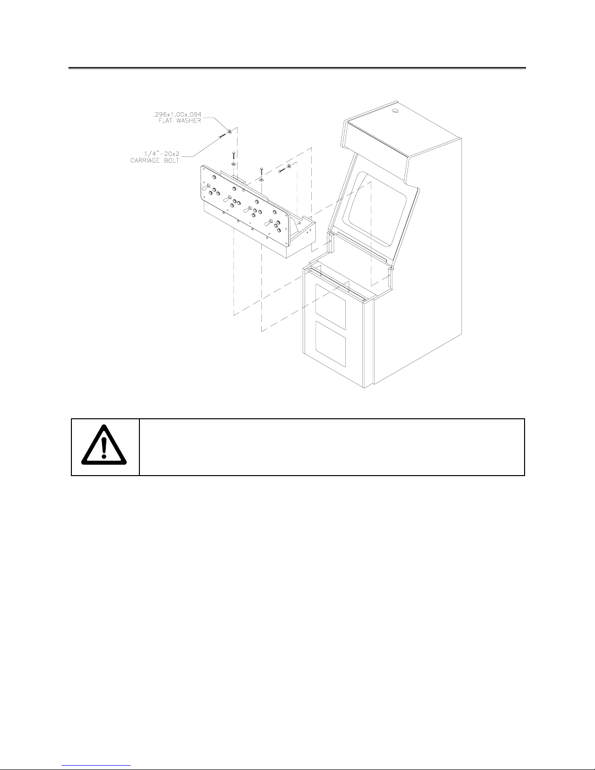
INSTALLATION & INSPECTION
INSTALL THE CONTROL PANEL
WARNING:
[ ] 1. Remove all items from the shipping containers. Inspect the exterior of the cabinet, and control
panel for damage. Pay special attention to cabinet edges, seams, and corners.
[ ] 2. Remove and save the screws at the top and sides of the rear door. Unlock the r ear door. T hen lift
it off the cabinet. Set the rear door aside. Ins pect the cabinet interior for s igns of damage. Check
all major assemblies to assure that they mount securely. Check the joysticks for signs of damage.
[ ] 3. The coin door keys are on a key hook inside the cabinet. Unlock and open the coin door. Cash
box door and rear door keys are on a key hook attached to the rear of the coin door. Unloc k and
open the cash box door. Remove the spare parts stored in the cash box.
[ ] 4. Find the leg levelers and nuts in the spare parts bag. Ins tall one nut onto each leg leveler. Hand-
turn the nut against the base of the leg leveler. Install one leveler with its nut into the threaded
hole in each corner of the cabinet. Turn the levelers all the way into the holes, but don’t tighten the
levelers.
[ ] 5. Unpack the player control panel (player panel). Place the player panel on the cabinet above the
coin door. Open the player panel. Align panel-mounting holes with holes in the cabinet. Install
bolts with washers (two in back; two on the bottom). Connect wiring harness es to P1, P2, and P8
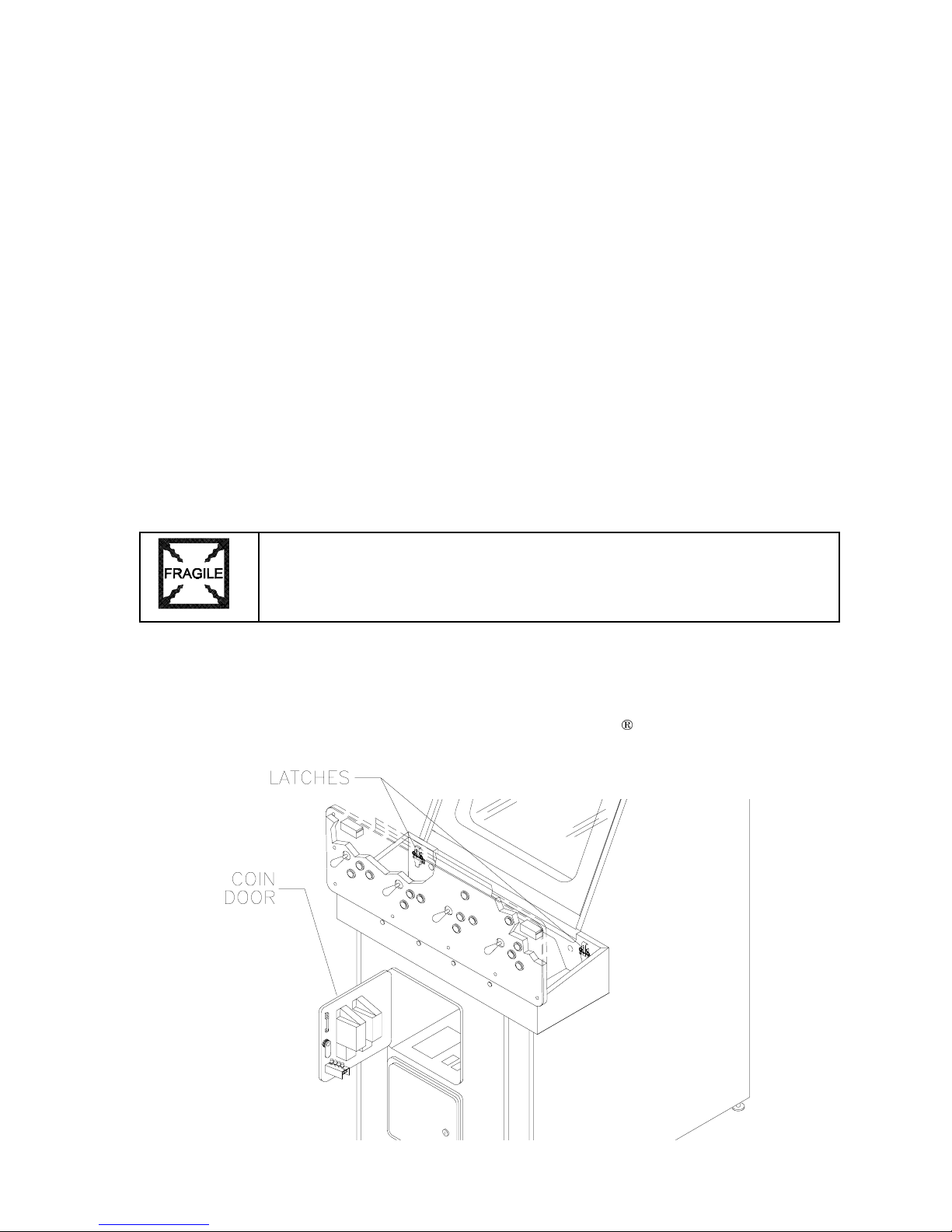
on the I-40 Joystick Interface Board. Close the player panel. Reach up through the open coin door
and lock both latches.
The cabinet is top heavy. Use the two handles when moving the cabinet.
Setup 1-4
Page 7
[ ] 6. Refer to the Cabinet Wiring Diagram (Chapter 5). Check to see that cable connectors are
correctly secured. Don’t force connectors. They’re keyed to fit in only one location. Bent pins and
reversed connections may damage your game and void the warranty.
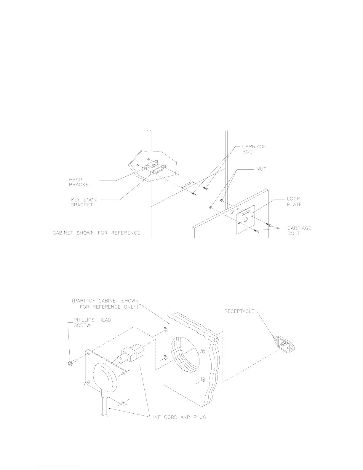
[ ] 7. You can install an extra padlock to secure the r ear door. You’ll find a hasp in the spare parts bag.
Remove the two lock brack et nuts f rom ins ide the cabinet, above the rear door opening. Slide the
hasp onto the bolts. Be sure that the hasp protrudes from the hole in back of the c abinet. Reinstall
nuts and tighten.
[ ] 8. Modify the lock plate at the top of the rear door: Remove the bolts and nuts f rom the lock plate.
Rotate the plate so that the slot is above the door. Reinstall bolts and nuts. Tighten them firmly.
INSTALL THE DOOR LOCK AND SECURITY BRACKETS
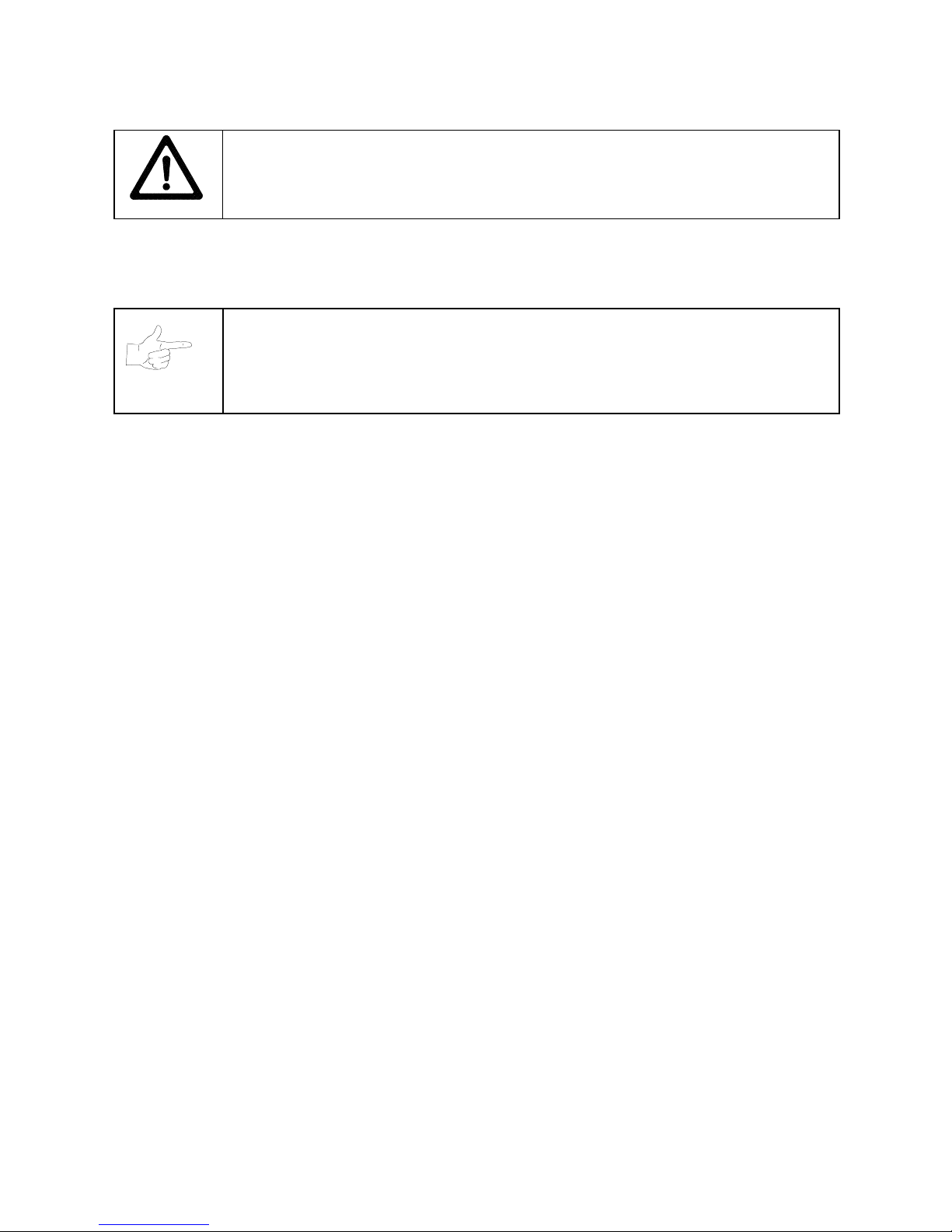
[ ] 9. The power c ord is with the spare parts. Find the line cord cover plate at the rear of the cabinet.
Remove and save the four screws from this plate. Match the holes on the IEC plug with the
prongs in the receptacle. Push the plug firm ly to seat it. Route the cor d away from c abinet wheels
and foot traffic areas. Hang excess cord on the plastic clip near the vent.
INSTALL THE LINE CORD
Setup 1-5
Page 8
CAUTION: CHECK POWER SUPPLY LINE VOLTAGE SELECTOR SWITCH.
Set the
110/220 VAC selector on the power supply for the correct local line voltage. Check the
selector setting before switching on the game.
[ ] 10. Reinstall the rear door and close it. Lock the rear door and rem ove the k ey. If required, install the
extra padlock through the hasp. Install the sc rews at the top and sides of the rear door. Tighten
the screws snugly. Close and lock the cash box and coin doors.
NOTICE:
For additional security, the factory provides tamper-resistant screws and a
matching wrench with this game. You’ll find four tamper-resistant screws and four
wrenches in the spare parts bag. If desired, replace the original screws with the tamperresistant screws. Tighten the screws firmly with the wrench.
[ ] 11. Move the game to its play location. Lower each leg leveler until the cabinet is stable and level.
Adjust the levelers as required to raise wheels and distribute weight equally on each corner.
Tighten the nuts.
[ ] 12. Plug the game into a grounded, 3-terminal, AC wall outlet. Switch on the game, using the switch at
the top-left, rear of the cabinet. The gam e will power up and begin self-diagnostic s. If diagnostics
find no errors, the game enters its Attract Mode of operation. Unlock and open the coin door.
Locate the control switches. Press TEST MODE to enter the Menu System.
[ ] 13. Select “MONITOR SETUP” at the Diagnostics Menu. Confirm proper video display operation and
adjust the monitor as necessary.
[ ] 14. Select “DISK TESTS” at the Diagnostic s Menu. Run all the tests in order to verify correct drive
operation.
[ ] 15. Select “SW ITCH TESTS” at the Diagnostics Menu. Check to be sure that all control switches
work.
[ ] 16. Select “DIP-SWITCH TESTS” at the Diagnos tics Menu. Ver if y that all switches are set to optimum
positions for this game.
[ ] 17. Select “SPEAKER TEST” at the Diagnostics Menu. Verify operation of audio system components.
[ ] 18. Select “EXIT” at the Main Menu. The system should enter Gam e-Over Mode. Open the c oin door
and press the SERVICE CREDITS button to allow game play. Choose a joystick and press the
START button to begin play. Listen to the audio while playing the game. Note sound irregularities
(phase problems, no low frequencies, mono audio from stereo speakers, etc.). If necessary,
check the wiring harness for internal shorts or strapped connections.
Setup 1-6
Page 9
1%$6
+2:7,0(*2/'(',7,21
1)/%
/,7=
*
2/'(',7,21
C H A P T E R
T W O
NOTICE:
The term VGM refers to the video game machine.
OPERATION
Operation 2-1
Page 10

VIDEO GAME MACHINE
(VGM)
OPERATION
STARTING UP
Whenever you turn on the machine or restore power, the system executes boot ROM code. The boot
ROM contains self-diagnostic tests. T hese tests automatically verify and report the condition of the disk
drive and other hardware. The screen is blank during these tests. If the hardware fails a test, the system
displays an error message. The message appears for 30 seconds or until someone presses a button.
•
If nobody presses a button, the system quickly completes tests, and then loads game software.
•
To skip boot ROM tests and activate the Menu System, press and hold the TEST MODE button. You’ll
find this button behind the coin door.
Having passed power-up tests, the VGM computer enters Attract Mode. Attract Mode cons ists of typical
game scenes and sounds, alternating with high scores. Attract Mode continues until game play
commences.
Players insert currency or tokens to start the gam e. Pressing a ST ART deter mines which player receives
the credit. The VGM computer ask s the players which game that they want to play: NBA Showtime Gold
Edition or NFL Blitz 2000 Gold Edition. Players request one or the other via player panel controls. Then
players select a team. The VGM computer associates one team with the Player–1 and Player-2 joysticks.
The Player–3 and Player-4 joysticks ass ume contr ol of the opposing team . Play begins after a countdown
period. Play progresses like a real-life football or basketball game. At Game-Over Mode, players may
choose to begin again. If players choose not to continue, then the VGM computer returns to Attract Mode.
GAME RULES FOR
INSTRUCTIONS
Play instructions appear on the information panel over and under the video monitor.
ONE TO FOUR PLAYERS
Players may enter their names for future refer ence. Then they select team s and run the fir st play. Players
may choose an offensive or defensive play. Additional game information appears on the screen as
needed. Team statistics appear at the end of each quarter.
CONTROLLING CHARACTERS
The joystick and action buttons control characters on the field. T he joysticks res pond to differ ent amounts
of deflection as well as direction.
GAME ACTION
Standard league football rules apply, with two exceptions: First downs require 30 yards, and teams only
have seven active players. Game adjustment settings determine game length and speed.
The player view of the action changes automatically whenever a better c amera angle becomes available.
The game sounds include announcer comments and crowd noises.
SCORING
Touchdowns and goals score points, just as in real football games.
NFL BLITZ 2000 GOLD EDITION
PLAY SELECTION FOR
STANDARD PLAYS
The player may select any of the offensive or defensive plays in the game. Players can choose from
pages of standard plays loaded into the game. Use the indicated pushbuttons to view and select any play.
NFL BLITZ 2000 GOLD EDITION
Operation 2-2
Page 11
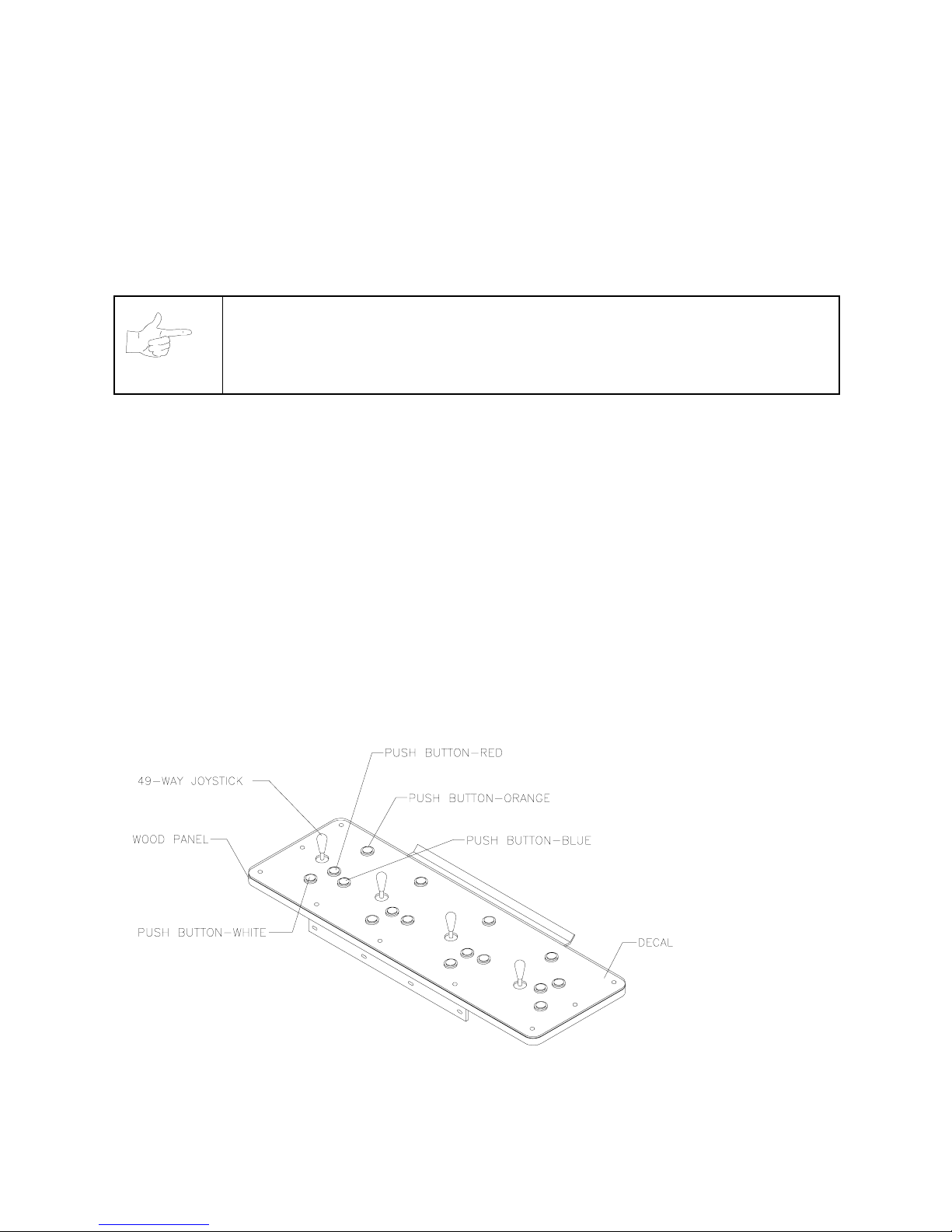
CUSTOM PLAYS
Players may choose to create their own offensive plays rather than depend on the standard plays in the
game. Players can design and name their plays using the CREATE PLAY featur e, then store thes e plays
for future use. These custom plays become available on an additional page of game plays.
PLAYER CONTROLS FOR
The player controls are used to maneuver the team members and attack or defend against adversaries.
NOTICE:
•
START.
START to begin a two-player game. START has no game action or service function.
•
JUMP / TACKLE.
tackle opponents. Use this same button to create plays or select menu items during service.
•
PASS / CHANGE PLAYER.
active control to another teamm ate. Use this same button to create plays or select menu item s during
service.
•
TURBO.
same button to create plays or select menu items during service.
•
JOYSTICK
time. Use the joystick to create plays or select menu items during service.
This button allows players to begin or continue play. Use PLAYER 1 START and PLAYER 2
This button lifts the offensive team member up or causes the def ensive player to
The TURBO button gives any active character an extra burst of power or speed. Use this
. Each player has a joystick to control the movements of one on-screen character at a
NFL BLITZ 2000 GOLD EDITION
Use joystick and button combinations to discover secret moves.
This button activates offensive throws. The defense move switches
PLAYER CONTROL LOCATIONS
Operation 2-3
Page 12

GAME RULES FOR NBA SHOWTIME GOLD EDITION
INSTRUCTIONS
Play instructions appear on the information panel over and under the video monitor.
ONE TO FOUR PLAYERS
The player or players insert currency to start the game. Each player chooses a joystick and presses the
nearest START button. Players select a team and two characters. In four-player games, each player
controls one character. In games with fewer players, each player controls one character. The VGM
computer controls r emaining characters. The VGM com puter displays team scores and statistics at the
end of each quarter. Additional game information appears on screen as needed.
CONTROLLING CHARACTERS
The joystick and action buttons control characters on the basketball court. The joysticks respond to
different amounts of deflection as well as direction.
GAME ACTION
Standard NBA basketball rules apply, except that the game only includes four active characters. Game
settings determine game length and speed. The player view of the action changes automatically whenever
a better camera angle becomes available. Game sounds include announcer comments and crowd noises.
SCORING
The game awards points for baskets, just as in real basketball games.
PLAYER CONTROLS FOR NBA SHOWTIME GOLD EDITION
•
JOYSTICK.
screen.
PASS/STEAL (the blue button)
•
to attempt to pass or steal the ball.
•
SHOOT/BLOCK (the red button)
SHOOT/BLOCK to shoot or attempt to block the ball.
•
START (orange buttons).
play.
•
TURBO (The white button)
up the pace of a play.
Each player’s joystick controls the position of that player’s characters on the video
controls character actions on the video screen. Press PASS/STEAL
controls character actions on the video screen. Press
Each START button allows the corresponding player to begin or continue
controls character actions on the video screen. Press TURBO to speed
GAME FEATURES OF NBA SHOWTIME GOLD EDITION
NBA Showtime is a thrilling, two-on-two basketball game with world-class realis m. Each player selects an
NBA team, and then chooses a favorite character. Players can also c reate their own players. If fewer than
four players are in the game, the computer operates the remaining characters.
Operation 2-4
Page 13
The red team comprises players 1 and 2. Players 3 and 4 make up the challenging, blue team . The red
and blue teams square off f or the j ump and the action begins. Run the ball down court! A s teal! Dribble up
court! A snap shot! The breathless announcer describes every pass, every shot, every block, every move!
After each quarter, new players can join the fun. Players can also switch to diff erent charac ters. When the
game concludes, team and individual scores appear on the screen. T op scor ers m ay enter their initials or
names with a joystick. NBA Showtime displays these initials in a high score table.
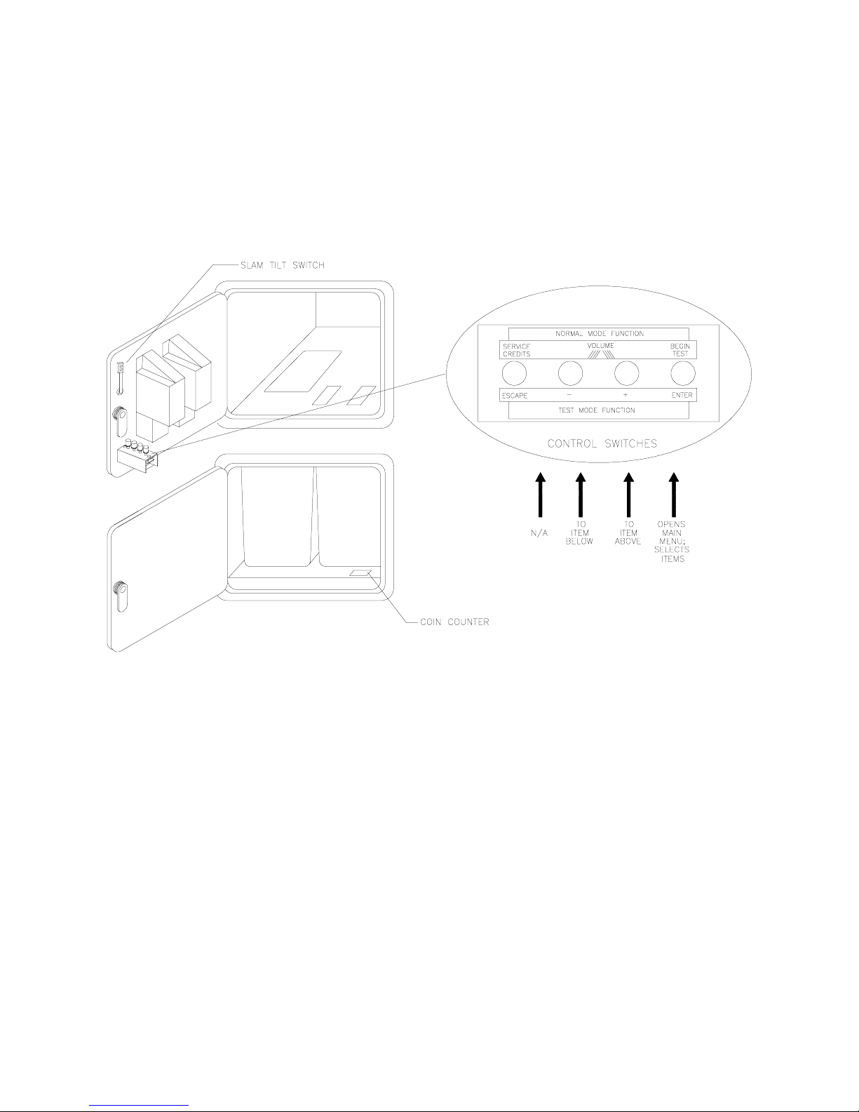
DIAGNOSTIC CONTROL SWITCH LOCATIONS
OPERATOR CONTROLS
CABINET CONTROLS
•
The DIP Switches
switches.
•
The Monitor Remote Control Board
•
The POWER Switch
DIAGNOSTIC CONTROL SWITCHES
•
The SERVICE CREDITS Button
SERVICE CREDITS has no function in the Menu System.
set some system variables. You can set other variables with diagnostic control
allows you to adjust the video display for optimum viewing.
turns off the video game machine, but does not reset game variables.
allots credits without changing the game's bookkeeping total.
Operation 2-5
Page 14
•
The TEST MODE Button
MODE button briefly to run automatic tests. To make game adjustments , pres s and hold T EST MODE
until the Main Menu appears. Within the Menu System, TEST MODE assumes another function.
There, it selects a menu line item and calls up the item’s submenu. The screen displays this
submenu.
•
VOLUME DOWN and VOLUME UP Buttons
changes, press either button briefly. To make major changes, press and hold a button. In the Menu
System, VOLUME UP moves the item highlight bar up the m enu. VOLUME DOW N moves the item
highlight bar downward.
causes the VGM to enter the service Menu System. Press the TEST
set game sound levels. To make minor volume
NOTICE:
For greater profits, increase volume levels to draw attention to this game.
You must adjust Attract Mode volum e independently of Game Mode volume.
MAINTENANCE
Cabinet
•
Use only non-abrasive cleaners to avoid damaging game graphics. Apply cleaner to a clean cloth or
sponge. Wipe the screen clean with this cloth or sponge. Do not apply cleaner directly on the cabinet!
Control Panel
•
Dirt or debris on the joysticks or buttons c an affect earnings. Apply the cleaner to a clean cloth. Use
the cloth to wipe the controls. Don’t apply the cleaner directly to the controls!
Viewing Glass
•
To clean the glass, you don’t need to switch off power to the VGM. Apply a mild glass cleaner to a
clean cloth or sponge. Use this to wipe the viewing glass. Do not apply the cleaner directly on the
glass! Liquid could drip down into switch or motor circuits and cause erratic VGM operation.
SERVICING
Only qualified service personnel should perform maintenance and repairs. The following product
guidelines apply to all VGM operators and service personnel. Notes, cautions and warnings appear
throughout this manual where they apply. Read the SAFETY pages thoroughly before beginning service.
Circuit Board Set
•
The VGM computer uses a set of three circ uit boards. The three boards include the CPU Board, I/O
Board and Video Board. Switch off power to the VGM. Open the rear door. To expose the circuit
boards, remove their perforated metal cover. Car efully note the orientation of the JAMMA connector
and other cables. Extract the harness and hard disk drive ribbon cable from the board connectors.
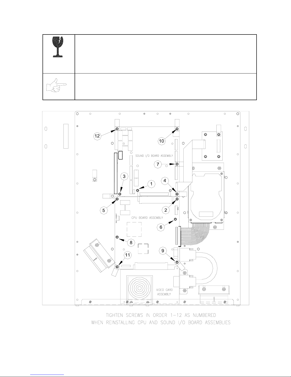
Remove circuit board mounting screws. Lift the circuit boards out of the cabinet and set them in a safe
place. Use anti-static packaging from new parts to store boards that you won’t reinstall.
Operation 2-6
Page 15
CAUTION:
Circuit board edge connectors are fragile. Take care when separating
boards in the board set. Never jam the boar d connectors together. Never plug them
together on an extreme angle. If necessary, carefully straighten bent pins with a
small, grounded flat blade screwdriver. Also, don’t touch exposed foil on printed
circuit boards. Skin oils are corrosive.
NOTICE:
Avoid damage to VGM electronics! Tur n off VGM power before servicing
circuit boards or any electronic assembly. Never “hot plug” circuit boards.
REINSTALLING CIRCUIT BOARD ASSEMBLIES
Operation 2-7
Page 16
Coin Mechanism
Switch off power to the VGM. Unlock the coin door and swing it open. To clean or replace a coin
mechanism, unlatch and remove it. After reinstallation, ensure that the mechanism seats fully its
bracket. Close and lock the release latch, and then close the door. Turn on the VGM and change the
mechanism setup. Test known good and bad coins to verify operation.
•
Coin Meter
Switch off power to the VGM. Unlock the cash door and swing it open. The coin m eter mounts to a
metal plate at the bottom the cash vault. Record the meter count before testing or replacement.
Remove the plate’s four mounting screws, and then remove the plate.
Disconnect the meter wiring harness at the connec tors. Rem ove f ront sc rews and slide the m eter out.
Assure that a protective diode connects across the replacement meter’s terminals. The diode
prevents driver circuit damage.
Hard Disk Drive
•
Switch off power to the VGM. Unlock and remove the rear cabinet door. Rem ove the perfor ated m etal
cover over the VGM electronics. Disconnec t the DC power cable from the hard disk drive. Unplug the
ribbon cable from the hard dr ive. Don’t disconnect the cables from the CPU Boar d. Loosen the drive
mounting screws and lift the drive out of its mounting bracket. Remove the sc rews. Save them for
reuse in future hard drive installations. When returning a hard dr ive to your distributor, pack it in an
anti-static bag. Box the drive in approved shipping container 08-8068.
NOTICE:
drop hard disk drives. Keep disk drives away from magnets, heat and vibration.
•
Joysticks
Switch off power to the VGM. Open the player control panel. Mark and disconnect the wiring harness
from a joystick. T o separate the joystick from the player panel, first remove the joystick shaft. An Ering secures the shaft. Disengage this E-ring with a small, flatblade sc rewdriver. Grasp the joystick
knob. Extract the stick from the assembly. Then r emove 8-32 KEPSI nuts from the corner s of the
joystick base. Retain fasteners for reassembly.
Hard disk drives are very fragile! Handle them with care. Do not stack or
Operation 2-8
Page 17
•
Memory
CAUTION:
destroy sensitive VGM circuits. BEFORE touching or handling electronic
assemblies, discharge static electricity by touching the electronics mounting plate.
NOTICE:
mounting chips on either board, refer only to chips on the same board for
reference. Never use chips another board for reference.
ROM (Read Only Memory) circuits contain com puter operating instructions for this VGM. Switch off
power to the VGM. Unlock and remove the r ear door. Remove the perforated m etal cover. Note the
ROM chip position. Remove the device with a chip extraction tool. To reinstall a ROM chip, orient the
device over its socket. Press the chip firmly to seat pins. Don’t force the chip into the socket.
Static electricity builds up on your body. This static can damage or
CPU Board and SI/O Board chips don’t face same direction. When
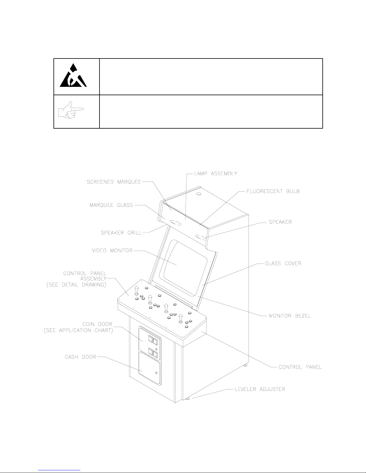
CABINET FRONT VIEW
Operation 2-9
Page 18
•
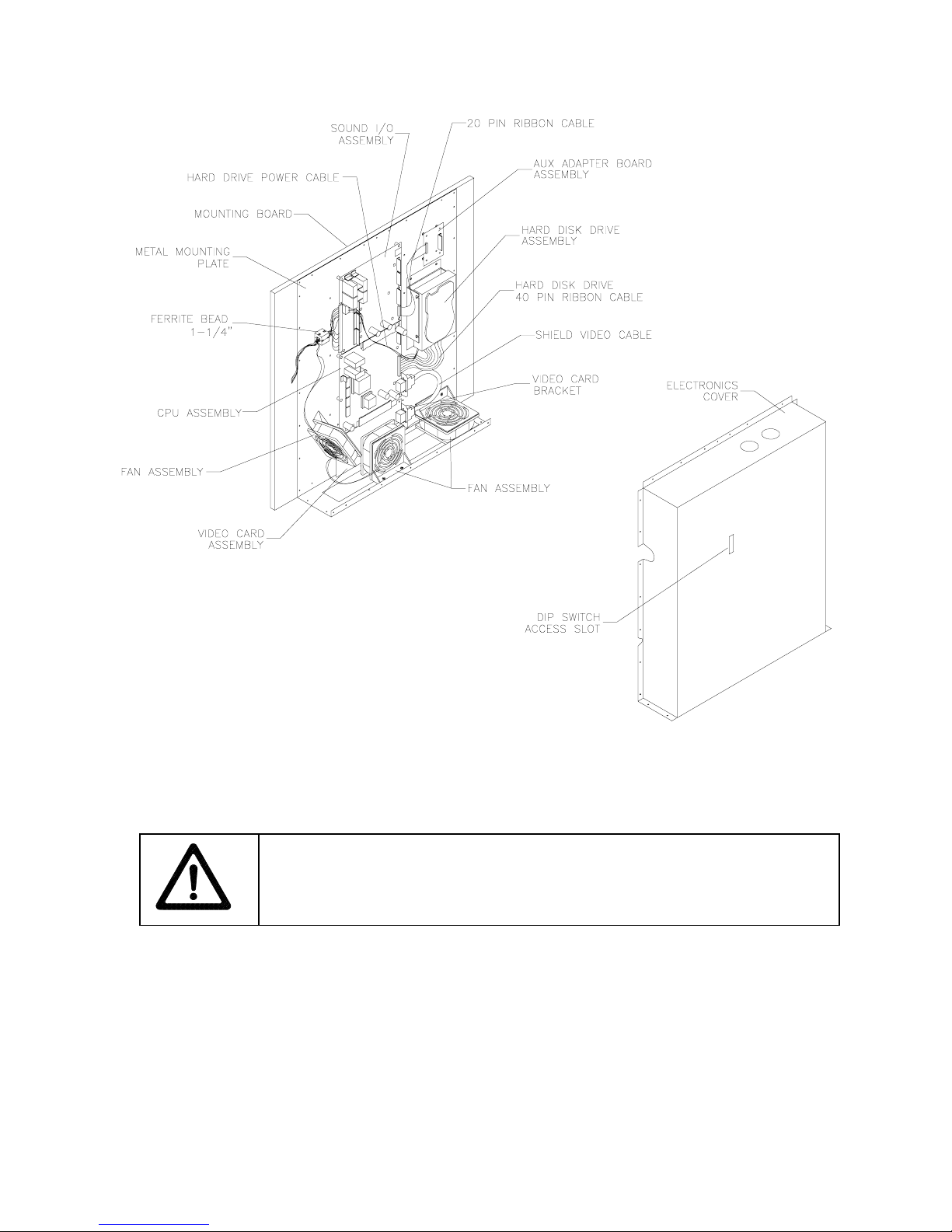
VGM ELECTRONICS, INTERNAL COMPONENTS
Monitor
CAUTION:
the assembly. Support the monitor as you remove it from the cabinet.
Switch off power to the VGM. Open the control panel. Remove the viewing glas s and monitor bezel.
Unlock and remove the rear door. Dis c onnect the monitor from the wiring harness , r emote adjustment
board, and ground wires. Remove the fastener s that secure the monitor frame to its m ounting panel.
Carefully pull the monitor from the cabinet. Set the monitor in a safe place. Remove the remote
adjustment board fr om the cabinet and reconnect it to the m onitor before servicing or r eplacement.
Clean the face of the CRT before reinstalling the monitor bezel.
The video monitor is heavy, with most of the weight toward the front of
Operation 2-10
Page 19

•
Monitor Bezel
Switch of f power to the game. Open the control panel. Remove the viewing glass. Lift the bezel up
and off the monitor. Set the bezel aside. Clean the labels. Orient the labels right side up, so that
players can read them. Reinstall the bezel.
Viewing Glass
•
Switch off power to the game. Open the contr ol panel. Loosen three m ounting s crews. Slide the blac k
metal strip from the bottom of the glass. Carefully slide the glass fr om the side grooves. Then lift it
clear of the cabinet. Set the glass in a safe place. Clean the glass before reinstalling it.
Operation 2-11
Page 20

NOTES
Operation 2-12
Page 21
1%$6
+2:7,0(*2/'(',7,21
1)/%
/,7=
*
2/'(',7,21
C H A P T E R
T H R E E
DIAGNOSTIC, AUDIT &
ADJUSTMENT MENU SYSTEM
FOR
NFL BLITZ 2000 GOLD EDITION
NOTICE:
make improvements in equipment as progress in engineering warrants.
NOTICE: GAME-SELECTION SWITCH.
switch 8 at DIP bank U13. Then power down an d up again. The Attract Mo de for the
game you select will appear. The player can still play either game.
This manual is subjec t to c ha nge witho ut n otic e. M i d wa y reserves the ri ght t o
Diagnostic, Audit & Adjust m ent Men u Sy st em for NFL 3-1
GAMES
Select NBA Showtime or NFL Bli tz by flipping
Page 22

MENU SYSTEM
WHAT IS THE MENU SYSTEM?
The game’s Menu S ystem is a series of aud iti ng, game adjustment and d ia gnostic screens. We call these
screens menus, becaus e the y pres ent opt ions in m enu-lik e list s. You c an eas il y access and appl y m enus
to optimize game performance. For instance…
•
Use game audits menus to assess game performance.
•
Use adjustment m enus to help you to customize gam e performance. For instance, you can restore
factory default game settings. You can also calibrate player controls for accuracy.
•
Use diagnostic menus to verify proper equipment operation.
ACTIVATING THE MENU SYSTEM
Open the coin door. Find the TEST MO DE switch inside. Pres s T EST MODE to invoke th e Menu System .
The game system responds by exiting G ame Mode and enter ing Diagnostic Mode. You can a lso invoke
the Menu System by turning on DIP bank U12, switch 8. (To reenter Game Mode, turn off switch 8.)
AUTOMATIC TE STS
In Diagnostic Mode, the Power-On Self-Test (POST) activates. This routine runs automatically. It can
detect faults that cause game or Menu System malf unctions. PO ST us ually tak es less than a m inute. T he
test doesn’t display anythi ng. Instead, the s ystem boot loader in dicates the soft ware revis ion num ber and
serial numbers. The system boot loader also displays a sound-loading message and other useful
information.
At the end of POST, the system displays the Control Functions Menu.
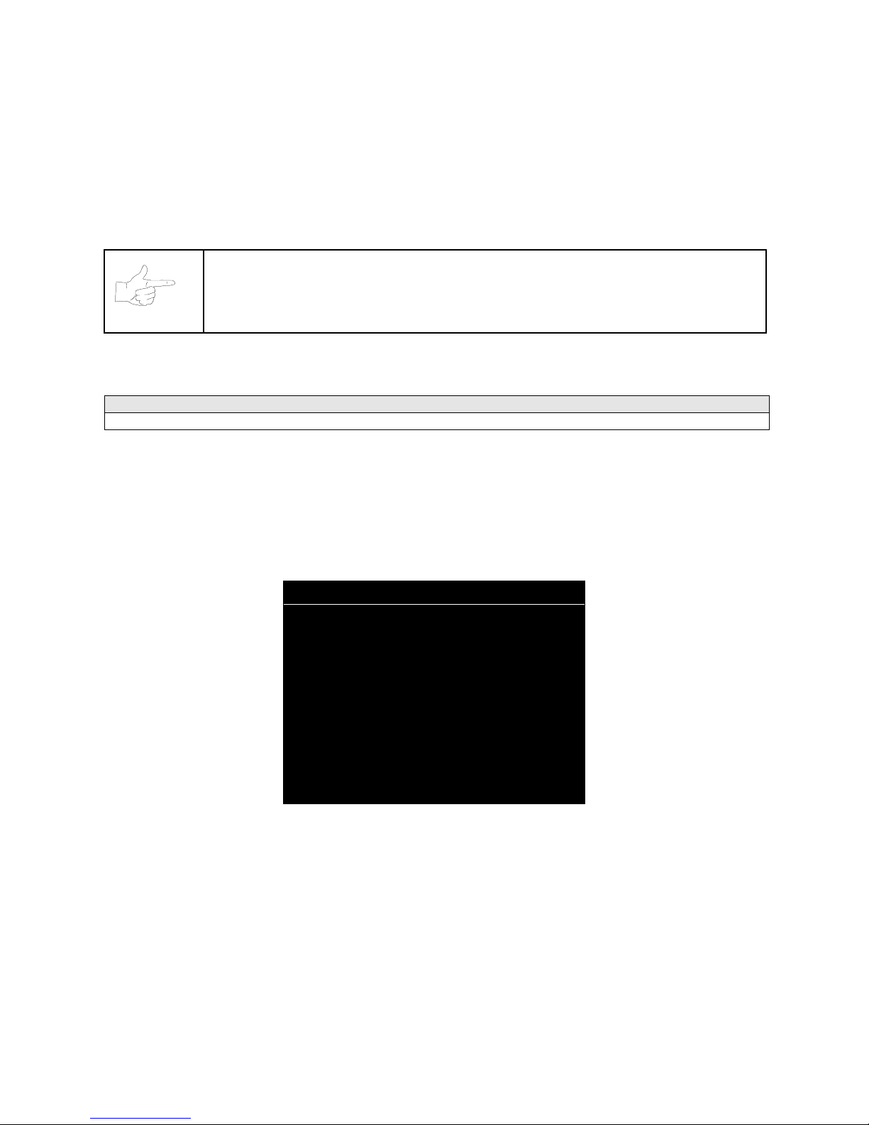
CONTROL FUNCTIONS MENU
The Control Functions M enu is purel y informational. It appears f or five sec onds. Then the Menu System
automatically displays the Dual Game Adjustment Menu.
The Control Functions Menu introduc es the menu navigation controls. T he key point is t hat you can use
either player or diagnost ic contro ls to nav igate menus . Diagnos tic contr ol switches are part icularl y helpful
when you must troubleshoot pla yer switches. This m anual discusses the controls in m ore detail in this
chapter’s Main Menu section. Also see the page on the menu that interests you.
STICK UP/VOLUME UP – MOVE UP
STICK DOWN/VOLUME DOWN – MOVE DOWN
STICK RIGHT – MOVE RIGHT
STICK LEFT – MOVE LEFT
PUSH BUTTON/TEST BUTTON - SELECT
5 SECONDS TO DIAG ENTRY
Diagnostic, Audit & Adjust m ent Men u Sy st em for NFL 3-2
CONTROL FUNCTIONS MENU
Page 23

DUAL GAME ADJUSTMENT MENU
The Dual Game Adjust ment Menu is another informational, r ead-only menu. It ap pears until you choos e
to exit. This m enu reminds you that som e NFL settings also affect NBA game play. Press any button to
exit to the Main Menu.
ATTENTION!
ANY CHANGES TO THE FOLLOWING ADJUSTMENTS
UPDATE BOTH NBA AND NFL
PRICING
FREE PLAY
VOLUME LEVEL
DISCOUNT PRICE / CREDITS
ATTRACT MODE SOUND ON / OFF
THIS ALSO INCLUDES DEFAULT ADJUSTME NTS
AND
FULL FACTORY RESTORE FUNCTIONS.
PRESS ANY BUTTON TO EXIT.
DUAL GAME ADJUSTMENT MENU
MAIN MENU
The Main Menu of fers you acces s to the gam e m achine’s test, b ookk eeping and pro gramm able featur es.
Game audits, adjustm ents and diagnostic s are line item s on the Main Menu . Selecting an item opens its
submenu. Every submenu presents various options that you
NFL MAIN MENU
DIAGNOSTICS
AUDITS
ADJUSTMENTS
VOLUME LEVEL
ATTRACT VOLUME LEVEL
UTILITIES
NBA MAIN MENU
EXIT TO NBA
EXIT TO NFL
MAIN MENU
MENU LAYOUT
Menus differ, but related information tends to occupy the same menu locations.
•
The block at the top, center of each menu displays the current menu title.
•
Data (menu items, video signals, statistics, reports, etc.) appears in the center of the menu.
•
Messages (explanations, control functions, revision levels) display at the bottom of the menu.
may act upon.
MENU NAVIGATION CONTROLS
Use any player panel j oystick to highlight a desire d menu item. You can only selec t one highligh ted item
at a time. To select a highlighte d item, press any pla yer panel button. O perator contro l buttons ins ide the
Diagnostic, Audit & Adjust m ent Men u Sy st em for NFL 3-3
Page 24
coin door serve as backup m enu navigation c ontrols. Pr ess VOLUME U P or VOLUME DOWN buttons to
highlight a menu item. Press TEST MODE to select a highlighted item.
EXIT OPTIONS
To exit the NFL menus and simultaneous ly enter the NBA menus, c hoose NBA MAIN MENU. To r eturn
the game to play, high light either EX IT TO NFL or EXIT T O NBA. Your choic e determines the gam e that
will boot. Next, press any button.
NOTICE:
This manual depicts some menus as ha ving two pages. Your video game
machine may present these same menus as one-pagers. Monitor resolution affects
whether a menu has a second screen.
Main Menu (continued)
Diagnostics Menu
DIAGNOSTICS
Select DIAGNOSTICS at the Main Menu. Dia gnos t ic tests all o w you to verif y the c on d ition of the electrica l
and electronic hardware in the game.
Highlight a test with any player panel joystick. Select the option with any player panel button.
DIAGNOSTICS
MONITOR SETUP
SYSTEM INFO
SOUND SUBSYSTEM
DISK TESTS
SWITCH TESTS
DIP-SWITCH TESTS
SPEAKER TEST
EXIT
DIAGNOSTICS MENU
Diagnostic tests ass ist you in ch ecking and adj usting the gam e’s major s ystems. By running d iagnostics,
you can gain an ins igh t i nto both system hardware and g ame software. Periodically runn in g diagnostics is
a crucial part of maintaining game performance and player satisfaction. Sometimes you can improve
game performance by running a diagnostic test and making appropriate adjustments.
Diagnostic, Audit & Adjust m ent Men u Sy st em for NFL 3-4
Page 25

Main Menu (continued)
Diagnostics Menu (continued)
Monitor Setup Menu
MONITOR SETUP
Select MONITOR SET UP at the D iagnos tics Menu. T he Mo nitor P atterns r outine pr ov ides tes t sc reens to
verify monitor performance or make adjustments.
Highlight an option with any player panel joystick. Select the option with any player panel button.
MONITOR SETUP
COLOR BARS
CROSSHATCH
RED SCREEN
BLUE SCREEN
GREEN SCREEN
WHITE SCREEN
BLACK SCREEN
50 PCT. GRAY SCREEN
25 PCT. GRAY SCREEN
EXIT
MONITOR SETUP MENU
Color Bars
fills the screen with colored stripes . Use the co lor bars to help you to check or adjus t monitor
brightness and contrast. T he color bars also ex pose defects in horizontal lin earity. Each color bar c ons ists
of 32 intensity levels. On a properl y adjusted monitor, the top 31 of these levels are visible. Each bar
should appear sharp, c lear and dist inct from bars on either side. Incorrect a djustment c an cause mis sing
detail at the top or bottom of a bar. Bent bars indicate horizontal linearity flaws, such as pie crust,
pincushion or barrel distortion. (Correct color bar colors, left to right: Red, Green, Blue, Black, White,
Cyan, Yellow, Violet.) Set controls as follows: 1. Adjust BRIGHTNESS and CONTRAST to minimum. 2.
Turn up BRIGHTNESS until the pixels in the black stripe begin to glow (t urn dark gray). 3. Brin g up the
CONTRAST control until you can see 31 bars.
Crosshatch Patterns
fill the screen wit h a grid and a series of dots. Crossha tch Patterns help you to
check or adjust several monitor param eters: These include convergence, linearity, active viewing area
and dynamic foc us. The grid and t he dots sho uld be all wh ite in col or, with no fr inges or parallel images.
The lines should b e straight and the dots round. F or more detail on these adj ustments, consult service
literature from the monitor manufacturer.
Color Screen
tests fill the scr een with 100% of the chosen co lor at normal intensit y. The Color Screen
tests help you to check or adjust monitor intensity, black level, blanking and color purity. Each screen
should be absolutel y uniform f rom top to bottom and side to side. No retrace lines or nois e should be
visible. Color Screens may not hold their uniformity if the monitor degaussing circuit is defective.
White, Gray and Black Screens
fill the screen with black, gray or white at various intensities. These
monochrome screens help you to check or adjust monitor convergence, purity, contrast and intensity.
These screens also simplif y black level a nd color gun control settings. The s creens should be uniform
with no color tints or distortion. No retrace lines or noise should be visible.
If tests indicate a need for adjustment, use controls on the Monitor Remote Adjustment Board.
Diagnostic, Audit & Adjust m ent Men u Sy st em for NFL 3-5
Page 26

Main Menu (continued)
Diagnostics Menu (continued)
System Information Menu
SYSTEM INFORMATION
Select SYSTEM INFO at the Diagnostics Menu. The System Information Menu provides the current
version numbers of this game’s hardware and software. Use these numbers to describe the system
during parts replacement, service calls, etc.
Highlight an option with any player panel joystick. Select the option with any player panel button.
SYSTEM INFORMATION
MIDWAY GAMES, INC.
XXXXXXX SYSTEM
SERIAL NUMBER: XXXXXXXXX
GAME: XXXXXXXXXX
DATE OF MANUFACTURE: XX/XX/XX
PRESS ANY BUTTON TO EXIT
SYSTEM INFORMATION MENU
The System Inform ation screen reports information, but doesn’t permit you to make changes. T he Title
line identifies the manufac turer of this gam e and the el ectronic board set used in th is product. T he Serial
Number, Game and Date of Manufacture identify the game name and production run.
Diagnostic, Audit & Adjust m ent Men u Sy st em for NFL 3-6
Page 27

Main Menu (continued)
Diagnostics Menu (continued)
Sound Subsystem Menu
SOUND SUBSYSTEM TEST
Select SOUND SUBSYSTEM at the Diagnostics Menu. Sound Subsystem Tests verify that audio
components are connected and operate properly.
Highlight an option with any player panel joystick. Select the option with any player panel button.
SOUND SUBSYSTEM TEST
BOOT VERSION: XX.XX
SDRC VERSION: XX.XX
PORT STATUS: GOOD
CHECKSUM: XXXX
SRAM: OK
DRAM: OK
TONE STATUS: GOOD
OS VERSION: XX.XX
PRESS ANY BUTTON TO EXIT
SOUND SUBSYSTEM MENU
Version, Status, Checksum and RAM Reports
are diagnostic routines. These routines analyze the
digital sound circuits and can detect sound memory problems. Test results appear as numbers or
messages. Sounds may also accompany some tests. Reports other than GOOD or OK indicate a
problem.
Diagnostic, Audit & Adjust m ent Men u Sy st em for NFL 3-7
Page 28

Main Menu (continued)
Diagnostics Menu (continued)
Disk Tests Menu
DISK TESTS
Select DISK TESTS at the D iagnostics M enu. Disk T ests allow you to verif y proper opera tion of the har d
disk drive assembly.
Highlight an option with any player panel joystick. Select the option with any player panel button.
DISK TESTS
DISK INFORMATION
SEQUENTIAL READ
SEQUENTIAL CACHE READ
RANDOM READ
RANDOM CACHE READ
DATA INTEGRITY TEST
FILE SYSTEM CHECK
SURFACE SCAN
EXIT
DISK TESTS MENU
Disk Information.
The Disk Information r outine verifies the i nterface between t he CPU Board Assem bly
and hard disk drive. T he processor requests disk information. Data cannot be retrieved successfully if
there is a problem.
Sequential Disk Read.
This routine tries to access ever y bit of data in the or der it is s tored directly on t he
disk. The hard disk drive media may be defective if this routine cannot be completed successfully.
Sequential Cache Read.
This routine tries to access every bit of data in the order it is stored in the
temporary disk memory cache. If this test is not successful, the memory circuits may be faulty.
Random Disk Read.
This routine tries to access every bit of data in no particular or der directl y from the
disk. This test m ay detect prob lems with ab ility to posi tion the dr ive heads accurat ely o ver the r equested
data.
Random Cache Read.
This routine tries to access every bit of data in no particular order from the
temporary disk memory cache. If the cache fails this test, memory circuits may contain a fault.
Data Integrity Test.
This test analyzes the dat a o n th e d is k drive. The test det ermines if corrupted da ta is
on the disk. Bad data can cause the program to falter even though the hard disk operates correctly.
File System Check.
Surface Scan.
This routine performs a file-by-file check of the data stored on the hard disk.
The magnetic material on the dis k can becom e dam aged, causing da ta to be unr eadabl e.
This routine locates unusable areas on the disk and marks them for future reference.
Diagnostic, Audit & Adjust m ent Men u Sy st em for NFL 3-8
Page 29
Main Menu (continued)
Diagnostics Menu (continued)
Switch Tests Menu
SWITCH TESTS
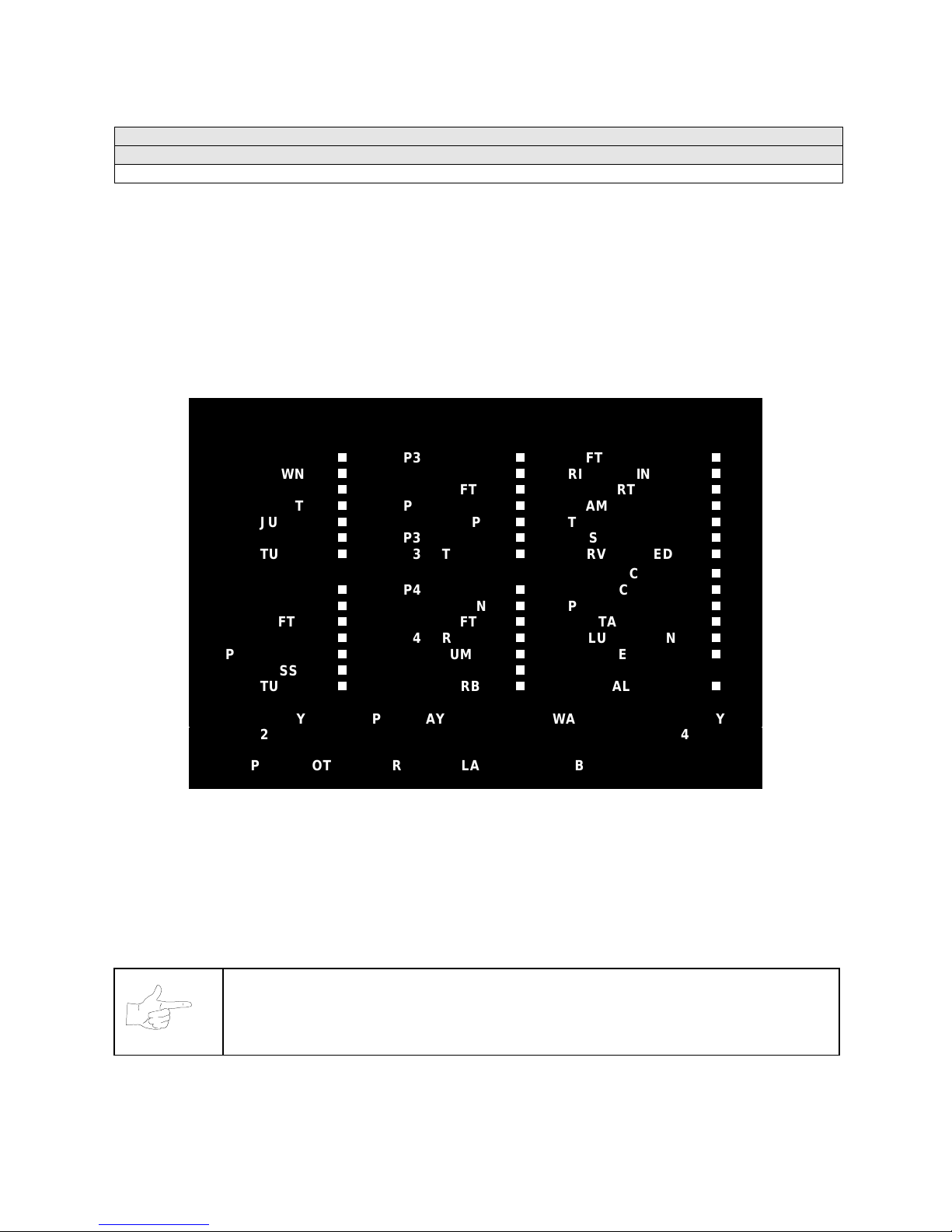
Select SWITCH TESTS at the Diagnostics Menu. Switch Tests verify proper operation of the game’s
switches, including buttons and joystick switches.
Activate each switch, and the indicator on the menu changes state. Release the switch and the indicator
returns to its previous, normally open or closed condition. You can test any combination of switches
together. To exit the test, simultaneously press the middle two control buttons inside the coin door. The
Switch Test Menu refers to these buttons as “volume buttons.”
PLAYER SWITCH INPUTS TEST
P1 UP
P1 DOWN
P1 LEFT
P1 RIGHT
P1 JUMP
P1 PASS
P1 TURBO
P2 UP
P2 DOWN
P2 LEFT
P2 RIGHT
P2 JUMP
P2 PASS
P2 TURBO
P1 49 WAY P2 49 WAY P3 49 WAY P4 49 WAY
24 24 24 24
PRESS BOTH PLAYER 1 AND PLAYER 2 START BUTTONS TO EXIT
P3 UP
P3 DOWN
P3 LEFT
P3 RIGHT
P3 JUMP
P3 PASS
P3 TURBO
P4 UP
P4 DOWN
P4 LEFT
P4 RIGHT
P4 JUMP
P4 PASS
P4 TURBO
LEFT COIN
RIGHT COIN
P1 START
SLAM/TILT
TEST
P2 START
SERVICE CREDIT
CENTER COIN
EXTRA COIN
P3 START
P4 START
VOLUME DOWN
VOLUME UP
BILL VALID.
SWITCH TEST MENU
Switches
appear on the menu as colored boxes. Red boxes indicate an open state. Green indicates
closed. Any other color indicates a fault condition. A single indication on the menu should exactly
duplicate a button or joystick change. You’ll notice a unique number for a switch recognized by game
electronics.
Use Switch Tests to locate crossed wires, intermittent conditions and stuck switches.
NOTICE:
Some switches may not be used with this game. If you can’t find one of the
listed switches, check the wiring diagram.
Diagnostic, Audit & Adjust m ent Men u Sy st em for NFL 3-9
Page 30
Main Menu (continued)
Diagnostics Menu (continued)
DIP Switch Tests Menu
DIP-SWITCH TESTS
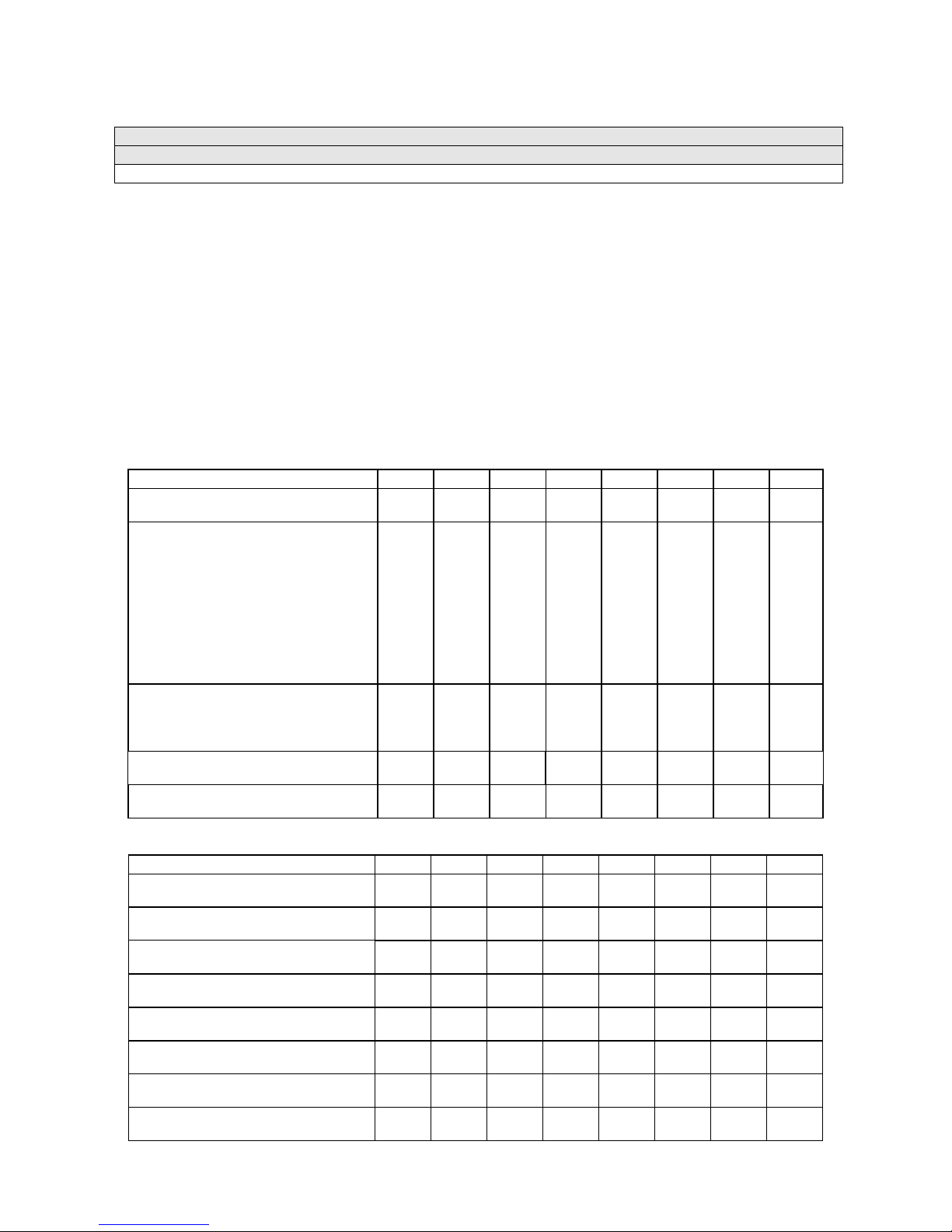
Select DIP-SW ITCH T EST S at th e Di agn os tics Me nu. Two 8-position DIP s witc h ba nks reside o n th e S IO
Board. DIP-Switch Tests allow you to check the position of the 16 switches in these banks. You can
change the setting of any DIP switch without removing the circuit board cage.
The menu displays an illustration of each switch block and th e current settings. You can change DIPswitch positions with power on. Set an y switch, and t hen check the menu to verif y that the ne w setting is
enabled.
Refer to the charts for assistance in choosin g switch positions. (* in dicates factory def aults.) To exit the
DIP-switch Test, press the left control button (inside the coin door).
Game-Selection Switch .
Select NBA Showtime or NFL Blitz b y flipping switc h 8 at DIP bank U13. T hen
power down and up again. After you change the game play, you must change game artwork.
DIP Switch 1 (U13)
Coinage Control DIP Switch
CMOS
USA1 Ger1 Fr ECA1 UK1
USA2 Ger2 Fr ECA2 UK2
USA3 Ger3 Fr ECA3 UK3
USA4 Ger4 Fr ECA4 UK4
USA5 Ger5 Fr ECA5 UK5
USA9 Ger9 Fr ECA9 UK9
USA10 Ger10 Fr ECA10 UK ECA
USA ECA / Ger ECA / Fr ECA8
Free Play (All Countries)
Country USA
France
Germany
UK**
Game Selection By player
By Switch 8
Game at power up NBA Showtime
NFL Blitz
SW1 SW2 SW3 SW4 SW5 SW6 SW7 SW8
Off
On*
Off*
On
Off
On
Off
On
Off
On
On
Off*
Off
On
On
Off
Off
On
On
On
Off*
Off
Off
Off
On
On
On
On
On
Off*
On
Off
On
Off*
Off
On
On
Off*
On
**Except Free Play, wh ich is “on” for SW2 through SW6.
DIP Switch 2 (U12)
Joystick Type 8-Way
49-Way
Monitor Resolution Medium Res
Low Res
Unused --
--
Unused --
--
Unused --
--
Player Panel Type 2-Player
4-Player
Power Up Test Active
Inactive
Operating Mode Game Mode
Test Mode
SW1 SW2 SW3 SW4 SW5 SW6 SW7 SW8
Off
On*
Off*
On
Off
On
Off
On
Off
On
Off
On*
Off
On*
Off*
On
Off*
On
Diagnostic, Audit & Adjust m ent Men u Sy st em for NFL 3-10
Page 31
Main Menu (continued)
Diagnostics Menu (continued)
Speaker Test Menu
SPEAKER TEST
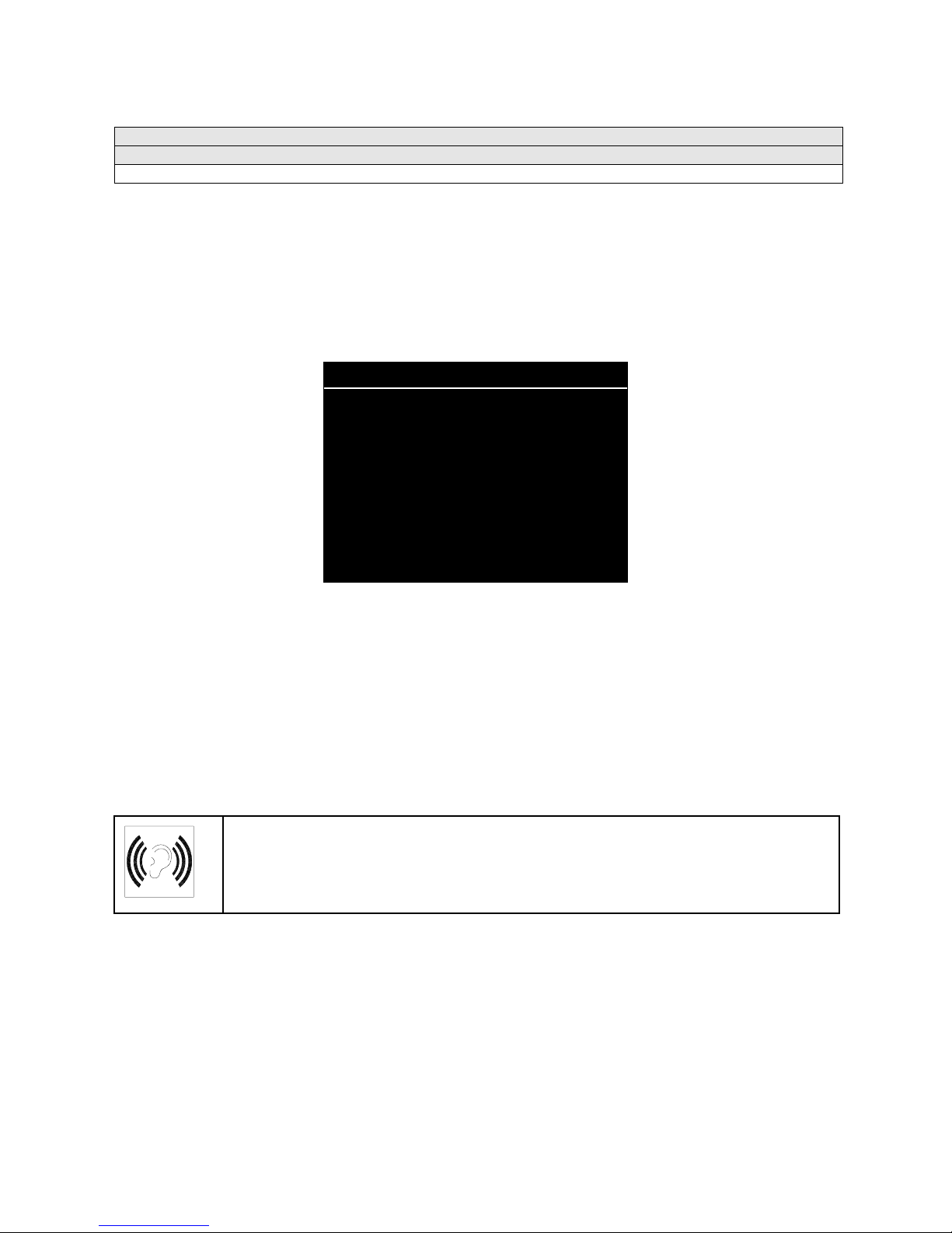
Select SPEAKER T EST at the Diagnostics Menu. The S peaker Test provides audio sig nals to test the
loudspeakers.
Use tests on the Speaker Test menu to ver ify operat ion of aud io system com ponents. Highlig ht an o ption
with any player panel joystick. Select the option with any player panel button.
SPEAKER TESTS
LEFT CHANNEL
CENTER CHANNEL
RIGHT CHANNEL
100 HZ TONE
1 KHZ TONE
PLAY TUNE
EXIT
SPEAKER TEST MENU
Channel and Tone Tests.
The channel subtests employ voice announcements to verify speaker
locations. Use the 100 Hz tone to check the speakers’ bass response. Small speakers with weak
magnets or poor baffles may cause poor bass response.
Play Tune
repeats a series of gam e sounds. Us e PLAY T UNE to check speaker operation and f idelit y. If
your game has stereo sp eakers, run PLAY TUNE and test sp eaker phasing. Muddy, weak or dis torted
sound during this test may ind icate crossed wires or out-of-phase speaker connections. Missing soun ds
may indicate audio cabling errors.
NOTICE:
Check the volume setting before testing. To test the speakers thoroughly,
increase the volume level. Before returning to Game-Over Mode, reset the volume
level to its original setting.
Diagnostic, Audit & Adjust m ent Men u Sy st em for NFL 3-11
Page 32
Main Menu (continued)
Audits Menu
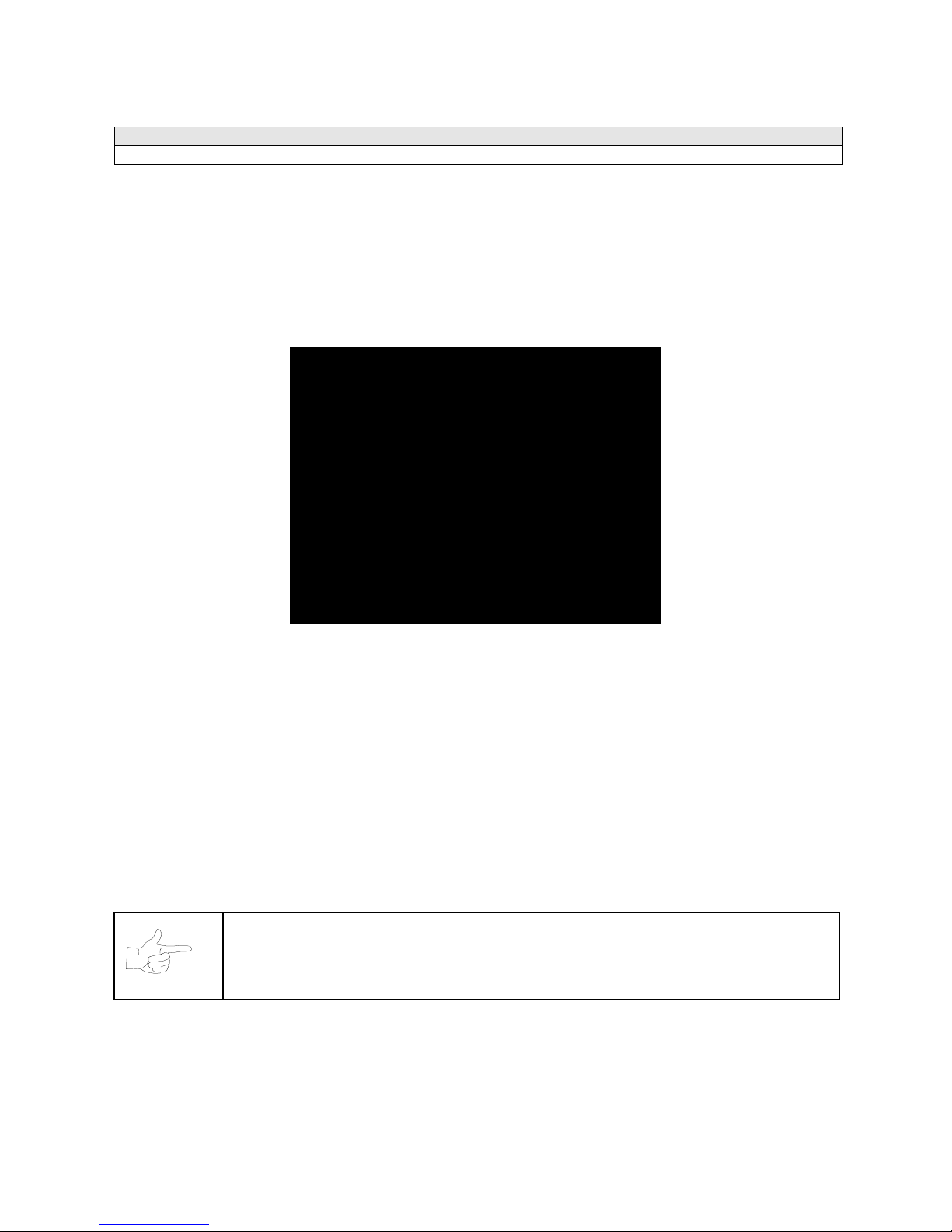
AUDITS
Select AUDITS at the Main Menu. The Audits menus perm it you to r ev iew game pla y st at istic s . Additional
menus give detailed reports for each player position on game starts, ends, cabinet abuse, fault
conditions, etc.
Highlight an option with any player panel joystick. Select the o ption with any player panel button. The
menu displays a list of the statistics available to you. Select an item to view the detailed report.
AUDITS
COIN AUDITS
CREDITS AUDITS
GAME AUDITS
TEAM STATS
OFFENSIVE PLAYS
DEFENSIVE PLAYS
EXCEPTION DUMP
CLEAR AUDITS
EXIT
AUDITS MENU
Data in the Audits m enus helps you t o keep records of the game’s popular ity and earning potenti al. Use
the highlight bar to select the desired subj ect on the Audits Menu. Each entry on t he Audits Menu is t he
subject for an entire m enu of bookkeeping inf ormation. On these m enus, y
frequently used offensive and defensive plays, etc
.
ou can track favorite teams,
Some audits menus als o inc lud e his tograms . Hist ogram me nus allo w gr aphic al analy sis of stat istics . T his
permits visual comparisons between games. Histograms have no bar graphs until the system acquires
enough data to plot.
Examine and record all game audit values before performing game service or repairs.
NOTICE:
Be careful when clearing audit inf ormation. Once you clear data, you c an’t
restore it.
Diagnostic, Audit & Adjust m ent Men u Sy st em for NFL 3-12
Page 33

Main Menu (continued)
Audits Menu (continued)
Coin Audits Menu
COIN AUDITS
Select COIN AUDITS at the Audits Menu. The Coin Audits menu permits you to assess the currency
collection. This report m enu prese nts revenu e quantit ies and o ther im portant gam e statist ics. Coin A udits
is a read-only menu.
To exit, press any player panel button.
COIN AUDITS – PAGE: 1
LEFT SLOT COINS
RIGHT SLOT COINS
BILLS
CENTER SLOT COINS
EXTRA SLOT COINS
GAME STARTS
MID-GAME STARTS
CONTINUES
FREE QUARTERS AWARDED
FREE GAMES AWARDED
SERVICE CREDITS
TOTAL PLAYS
XXXXXXXX
XXXXXXXX
XXXXXXXX
XXXXXXXX
XXXXXXXX
XXXXXXXX
XXXXXXXX
XXXXXXXX
XXXXXXXX
XXXXXXXX
XXXXXXXX
XXXXXXXX
UP - NEXT / BUTTON - EXIT
COIN AUDITS MENU, PAGE 1
The Coin Audits menu reports total quantities of coins, bills or credits collected by each active device. The
menu doesn’t calculate the value of the collected currency.
This menu reports i nformation, but doesn ’t perm it you to mak e changes. To res et the coin, bill and credit
counters to zero, use the Clear Audits menu.
We recommend that you examine and record au dit information bef ore you make changes . Once you’ve
cleared the counters, you can’t retrieve the previous data from the system.
COIN AUDITS – PAGE: 2
TOTAL PAID CREDITS
TOTAL
XXXXXXXX
XXXXXXXX
DOWN - PREV / BUTTON - EXIT
COIN AUDITS MENU, PAGE 2
Diagnostic, Audit & Adjust m ent Men u Sy st em for NFL 3-13
Page 34

Main Menu (continued)
Audits Menu (continued)
Credits Audits Menu
CREDITS AUDITS
Select CREDITS AUDITS at the Audits Menu. The Credits Audits menu permits you to assess the
currency collection. This report menu presents revenue quantities and other important game statistics.
Credit s Audits is a read-only menu.
To exit, press any player panel button.
CREDITS AUDITS - PAGE: 1
CREDITS AVAILABLE XXXXXXXX
PRESS ANY BUTTON TO EXIT
CREDITS AUDITS MENU
Diagnostic, Audit & Adjust m ent Men u Sy st em for NFL 3-14
Page 35
Main Menu (continued)
Audits Menu (continued)
Game Audits Menu
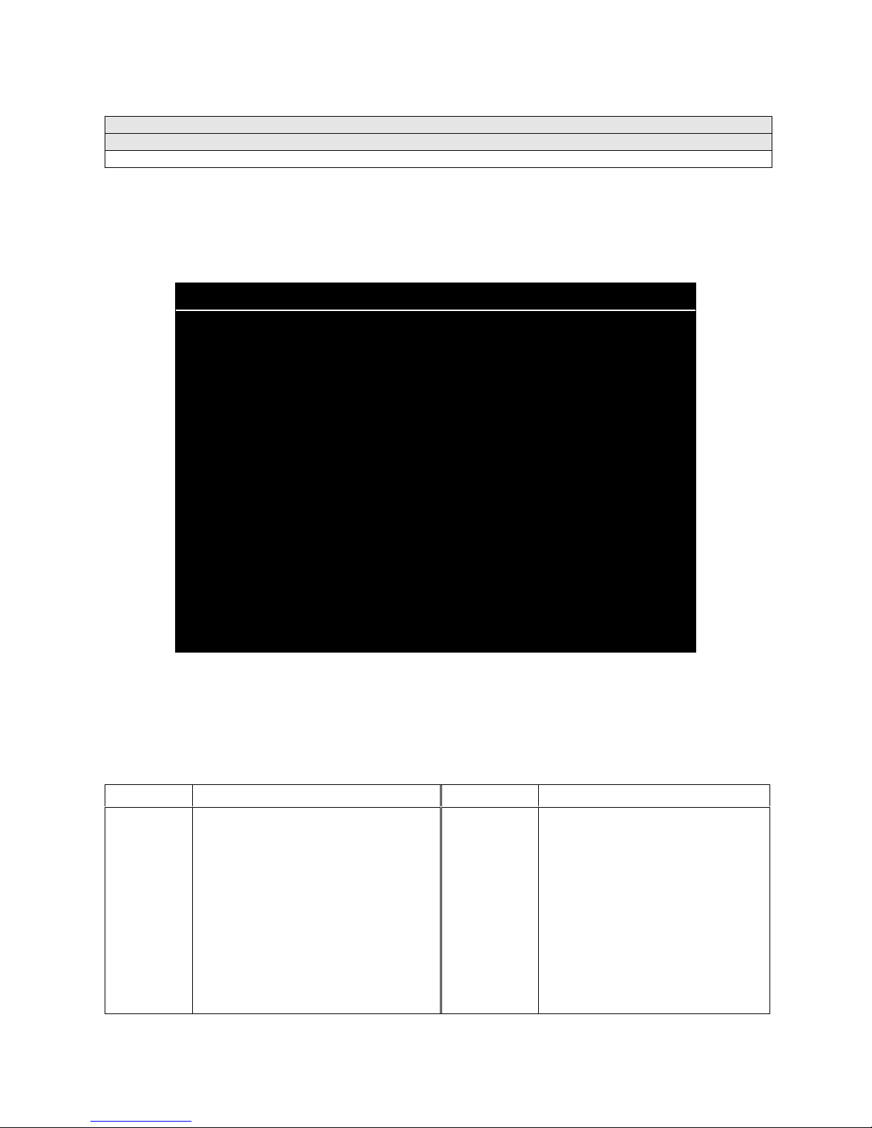
GAME AUDITS
Select GAME AUDITS a t the Audits Menu. The Gam e Audits m enus perm it you to review t he gam e play
statistics. Game Audits is a read-only menu.
To exit, press any player panel button.
GAME AUDITS - PAGE: 1
TOTAL UPTIME
TOTAL PL AY TIME
GAME STARTED
INITIALS ENTERED
<FG> PURCHASED AT START
CREATE PLAY SESSIONS
1 PLAYER
2 PLAYER
3 PLAYER
4 PLAYER
2P V CPU
1 QUARTER GAMES
XX
XX
XX
XX
XX
XX
XX
XX
XX
XX
XX
XX
2 QUARTER GAMES
3 QUARTER GAMES
4 QUARTER GAMES
WENT INTO OVERTIME 1
WENT INTO OVERTIME 2
WENT INTO OVERTIME 3
1 PLAYER FINISHES
2 PLAYER FINISHES
3 PLAYER FINISHES
4 PLAYER FINISHES
2P V CPU FINISHES
H VS H LSW’S
CPU WINS (FG)
AVG H VS H TOTAL SCORE (FG)
AVG H VS CPU TOTAL SCORE (FG)
AVG H VS H WIN SCORE (FG)
XX
XX
XX
XX
XX
XX
XX
XX
XX
XX
XX
XX
XX
XX
XX
XX
UP – NEXT / BUTTON - EXIT
GAME AUDITS MENU, PAGE 1
The Game Audits menu reports information, but doesn’t permit you to make changes. Examine and
record information at G AME AUDIT S before deleti ng dat a at the Clear Audits Menu. Once you’ve clea red
the counters, you can’t retrieve the previous data from the system.
TERM
AVG
CPU
Average
Central Processing Unit: The game
DEFINITION TERM DEFINITION
computer
<FG>, (FG)
H VS CPU
Full Game
Human versus CPU: Competition that
pits players against the game computer
H VS H
Human versus human: Competition
between human players
Diagnostic, Audit & Adjust m ent Men u Sy st em for NFL 3-15
GAME AUDIT MENU TERMS
LSW
Machine
Power-On
OT
P V
Total Uptime
2PV
Your game computer’s internal
record-keeping counters
Number of power cycles (game turnons)
Overtime
Player versus…
Overall on-time for the game
computer
Two players versus…
Page 36

GAME AUDITS - PAGE: 2
AVG H VS H LOSS SCORE (FG)
BIGGEST CPU WIN MARGIN (FG)
BIGGEST CPU LOSS MARGIN (FG)
TLF’S
SBLF’S
DOWN – PREV / BUTTON - EXIT
GAME AUDITS MENU, PAGE 2
XX
XX
XX
XX
XX
Diagnostic, Audit & Adjust m ent Men u Sy st em for NFL 3-16
Page 37

Main Menu (continued)
Audits Menu (continued)
Team Stats Menu
TEAM STATS
Select TEAM STATS at the Audits Menu. Team
in the league. Team Stats is a read-only menu.
To exit, press any player panel button.
TEAM STATS – PAGE: 1
ARIZONA CARDINALS
ATLANTA FALCONS
BALTIMORE RAVENS
BUFFALO BILLS
CAROLINA PANTHERS
CHICAGO BEARS
CINCINNATI BENGALS
CLEVELAND BROWNS
DALLAS COWBOYS
DENVER BRONCOS
DETROIT LIONS
GREEN BAY PACKERS
INDIANAPOLIS COLTS
JACKSONVILLE JAGUARS
KANSAS CITY CHIEFS
MIAMI DOLPHINS
Stats details the number of games played by each team
0
0
0
0
0
0
0
0
0
0
0
0
0
0
0
0
MINNESOTA VIKINGS
NEW ENGLAND PATRIOTS
NEW ORLEANS SAINTS
NEW YORK GIANTS
NEW YORK JETS
OAKLAND RAIDERS
PHILADELPHIA EAGLES
PITTSBURCH STEELERS
SAN DIEGO CHARGERS
SAN FRANCISCO
SEATTLE SEAHAWKS
ST. LOUIS RAMS
TAMPA BAY BUCS
TENNESSEE TITANS
WASHINGTON REDSKINS
0
0
0
0
0
0
0
0
0
0
0
0
0
0
0
Diagnostic, Audit & Adjust m ent Men u Sy st em for NFL 3-17
PRESS ANY BUTTON TO EXIT
TEAM STATS MENU
Page 38

Main Menu (continued)
Audits Menu (continued)
Offensive Plays Menu
OFFENSIVE PL AYS
Select OFFENSIVE PLAYS at the Audits Menu. Offensive Plays accounts for each play type as a
percentage of all offensive plays. Offensive Plays is a read-only menu.
To exit, press any player panel button.
OFFENSIVE PLAYS – PAGE: 1
TEAMPLAY 1
TEAMPLAY 2
TEAMPLAY 3
ZIG ZAG
SPIDER LEGS
MONKEY
SLIP SLIDE
QB POST
QUICK DISH
UPPER CUT
DA BOMB
HAIL MARY 2
TURMOIL
BACK SPLIT
SUBZERO
DAWG HOOK
U.T.B. DEEP
CROSS SLANT
PRESS ANY BUTTON TO EXIT
0%
0%
0%
0%
0%
0%
0%
0%
0%
0%
0%
0%
0%
0%
0%
0%
0%
0%
BLIZZARD
CRISS CROSS
UP THE GUT
SCREEN RIGHT
SUPER FLY
MIDDLE PICK
SWEEP RIGHT
REVERSE ZIP
HB BLOCK
EXTRA PLAY 1
EXTRA PLAY 2
EXTRA PLAY 3
EXTRA PLAY 4
EXTRA PLAY 5
EXTRA PLAY 6
EXTRA PLAY 7
EXTRA PLAY 8
EXTRA PLAY 9
0%
0%
0%
0%
0%
0%
0%
0%
0%
0%
0%
0%
0%
0%
0%
0%
0%
0%
Diagnostic, Audit & Adjust m ent Men u Sy st em for NFL 3-18
OFFENSIVE PL AYS M ENU , PAGE 1
OFFENSIVE PLAYS – PAGE: 2
PUNT
FAKE PUNT
FIELD GOAL
FAKE F.G.
EXTRA POINT
PRESS ANY BUTTON TO EXIT
0%
0%
0%
0%
0%
OFFENSIVE PL AYS M ENU , PAGE 2
Page 39

Main Menu (continued)
Audits Menu (continued)
Defensive Plays Menu
DEFENSIVE PLAYS
Select DEFENSIVE PLAYS at the Audits Menu. Defensive Plays accounts for each play type as a
percentage of all defensive plays. Defensive Plays is a read-only menu.
To exit, press any player panel button.
DEFENSIVE PLAYS – PAGE: 1
SAFE COVER
1 MAN BLITZ
2 MAN BLITZ
SUICIDE BLITZ
ZONE BLITZ
NEAR ZONE
MEDIUM ZONE
DEEP ZONE
GOAL LINE
EXTRA PLAY 1
EXTRA PLAY 2
EXTRA PLAY 3
EXTRA PLAY 4
EXTRA PLAY 5
EXTRA PLAY 6
EXTRA PLAY 7
EXTRA PLAY 8
EXTRA PLAY 9
0%
0%
0%
0%
0%
0%
0%
0%
0%
0%
0%
0%
0%
0%
0%
0%
0%
0%
BLOCK FG
BLOCK PUNT
PUNT RETURN
0%
0%
0%
Diagnostic, Audit & Adjust m ent Men u Sy st em for NFL 3-19
PRESS ANY BUTTON TO EXIT
DEFENSIVE PLAYS MENU
Page 40
Main Menu (continued)
Audits Menu (continued)
Exception Dump Menu
EXCEPTION DUMP
Select EXCEPTION DUMP at the Audits Menu. Game programmers use the Exception Dump Menu to
view register contents during program development. This menu has no field purpose. Exception Dump is
a read-only menu.
To exit, press any player panel button.
Main Menu (continued)
Audits Menu (continued)
Clear Audits Menu
CLEAR AUDITS
Select CLEAR AUDITS at th e Au dits M en u. The Clear Audits m enu al lo ws you to clear ind ivid ual memory
counters or to reset them all at once.
Highlight an option with any player panel joystick. Select the option with any player panel button.
CLEAR AUDITS
CLEAR COIN AUDITS
CLEAR CREDIT AUDITS
CLEAR GAME AUDITS
CLEAR TEAM STATS
CLEAR OFFENSIVE PLAYS
CLEAR DEFENSIVE PLAYS
CLEAR EXCEPTION DUMP
CLEAR ALL
EXIT
CLEAR AUDITS MENU
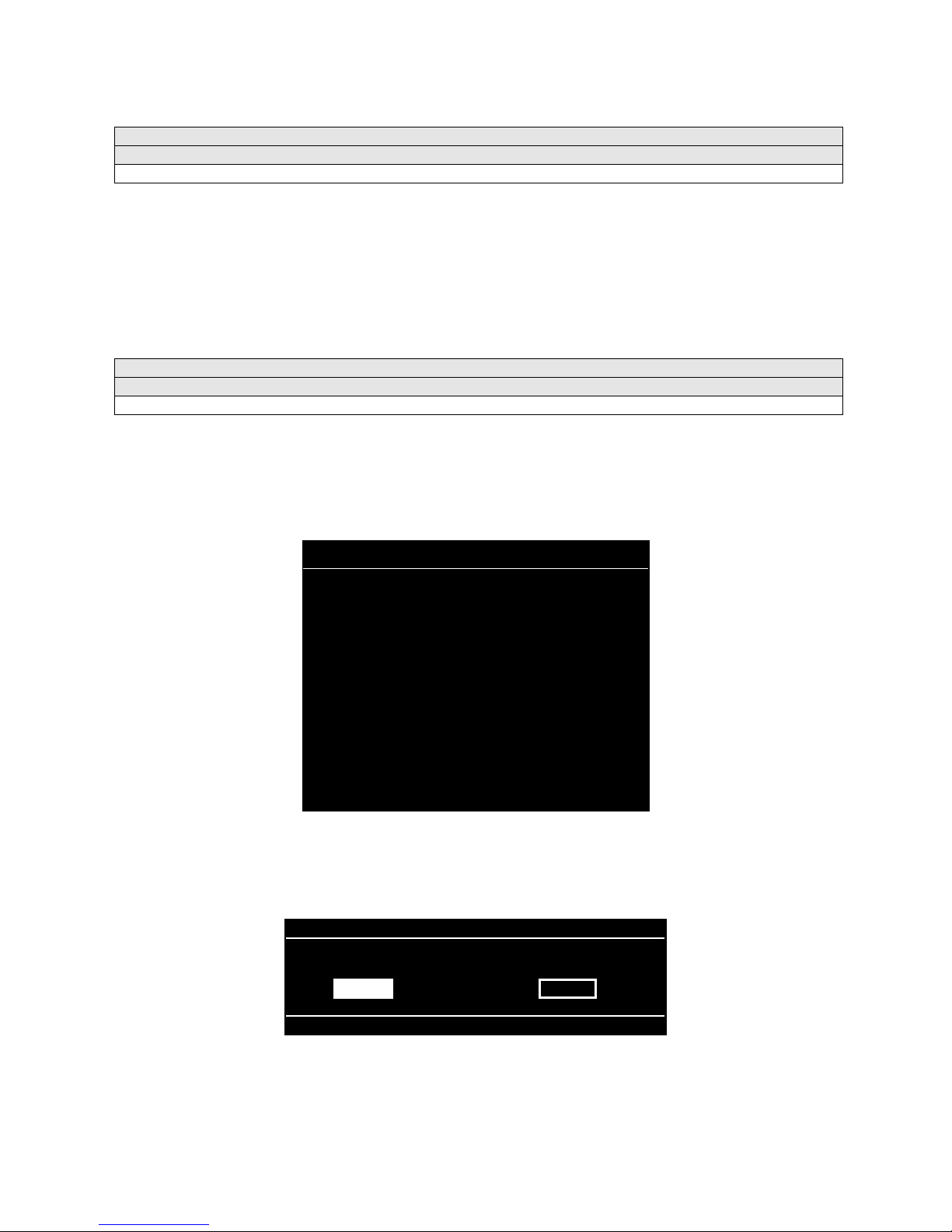
You can reset any audit menu from the Clear A udits Men u. Choose an item and zero its counter. C LEAR
ALL simultaneousl y changes all au dit categories t o factor y default va lues. After you’ve selected an item,
the system gives you the opportunity to escape this change. For example:
ARE YOU SURE YOU WANT TO CLEAR COIN AUDITS?
YES NO
LAST CHANCE MENU
After you’ve selected an d ver if ied a cl ear f unc tion, the values res et. The system can’t restor e the pr e vious
values. Examine and recor d uti lity values before you mak e changes.
Diagnostic, Audit & Adjust m ent Men u Sy st em for NFL 3-20
Page 41

Main Menu (continued)
Adjustments Menu
ADJUSTMENTS
Select ADJUSTMENTS at the Main Menu. The Adjustments menus permit you to change game
characteristics. Use these menus to optimize game performance and earnings.
Highlight an option with any player panel joystick. Select the option with any player panel button.
ADJUSTMENTS
PRICING
FREE PLAY
ATTRACT SOUND
ADDITIONAL ADJUSTMENTS
FULL FACTORY RESTORE
EXIT
ADJUSTMENTS MENU
Main Menu (continued)
Adjustments Menu (continued)
Pricing Menu
PRICING
Select PRICING at the Adjustments Menu. The Pricing menus allow you to view current settings or
change the cost of games. Custom pricing allows you to selec t the num ber of coins or credi ts requ ired f or
each game. The game restores factory default values if you exchang e the CPU Board or if the back up
battery fails.
Highlight an option with any player panel joystick. Select the option with any player panel button.
You may reset options to factory defaults or change an option af ter viewing it. W e recomm end examining
and recording pricing options before making changes.
You may save sever al custom prices and then choose be tween th em as needed. On- screen instructions
guide you through the process of creating custom price settings.
PRICING
SHOW CURRENT
NORTH AMERICA
SOUTH AMERICA
EUROPE (A-H)
EUROPE (I-U)
ASIA
AUSTRALIA
CUSTOM PRICING
EXIT
PRICING MENU
An additional box appears on screen to explain the available functions as you select each item.
Diagnostic, Audit & Adjust m ent Men u Sy st em for NFL 3-21
Page 42
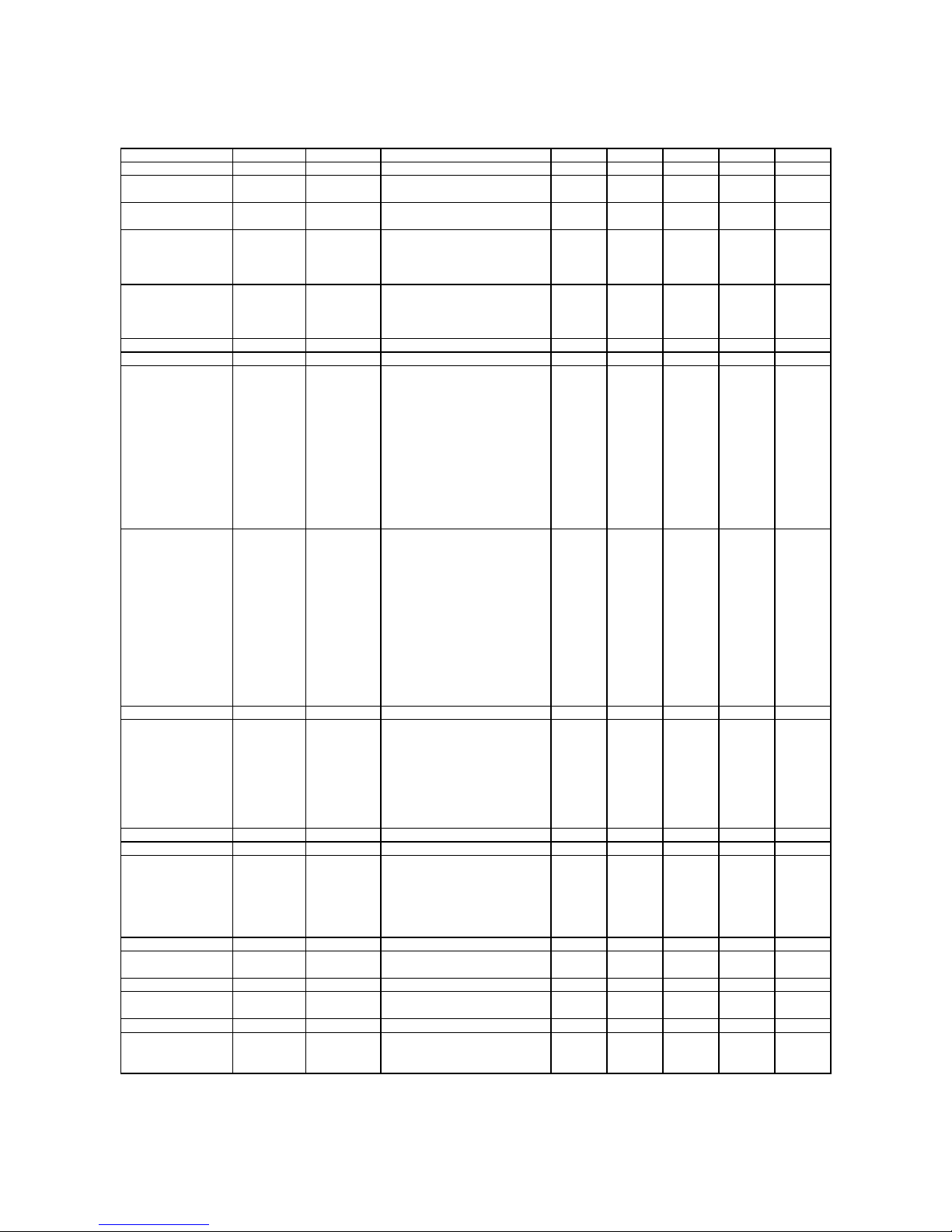
STANDARD PRICING TABLE
NAME START CONTINUE CREDITS/COIN COIN 1 COIN 2 COIN 3 COIN4 BILL
ANTILLES 2 2 1/25¢, 4/1G .25¢ 1G
AUSTRALIA 1 2 2 1/3X20¢, 2/$1.00 .20¢ $1.00
AUSTRALIA 2 1 1 1/5X20¢, 1/$1.00 .20¢ $1.00
AUSTRIA 1 2 2 1/5Sch, 2/10Sch 5 Sch 10 Sch
AUSTRIA 2 2 2 1/2X5Sch, 3/2X10Sch 5 Sch 10 Sch
BELGIUM 1 2 2 1/20BF 20BF 20BF
BELGIUM 2 2 2 3/20BF 20BF 20BF
BELGIUM 3 2 2 2/20BF 20BF 20BF
BELGIUM ECA 2 2 1/20BF 50BF 20BF 5BF
CANADA 1 2 2 1 / 2 x 25¢, 3 / $1 25¢ 25¢
CANADA 2 2 2 1 / 2 x 25¢, 3 / $1 25¢ $1.00
CANADA 3 2 2 3 / $1.00, 6 / $2.00 $1.00 $2.00
CANADA ECA 2 2 1 / 2 x 25¢, 3 / $1 25¢ $1.00 $2.00
DENMARK 2 2 3/5DKr, 7/10DKr 5DKr 10DKr
FINLAND 2 2 1/1Fmk 1Fmk 5Fmk
FRANCE 1 2 2 2/5Fr, 5/10Fr 5Fr 10Fr
FRANCE 2 2 1 2/5Fr, 4/10Fr 5Fr 10Fr
FRANCE 3 2 1 1/5Fr, 3/10Fr 5Fr 10Fr
FRANCE 4 2 1 1/5Fr, 2/10Fr 5Fr 10Fr
FRANCE 5 2 1 2/5Fr, 5/10Fr, 11/2 X 10Fr 5Fr 10Fr
FRANCE 6 2 1 2/5Fr, 4/10Fr, 9/2 X 10Fr 5Fr 10Fr
FRANCE 7 2 1 1/5Fr, 3/10Fr, 7/2 X 10Fr 5Fr 10Fr
FRANCE 8 2 1 1/5Fr, 2/10Fr, 5/2 X 10Fr 5Fr 10Fr
FRANCE 9 2 1 1/3 X 1Fr, 2/5Fr 1Fr 5Fr
FRANCE 10 2 1 1/2 X 1Fr, 3/5Fr 1Fr 5Fr
FRANCE 11 2 1 1/3 X 1Fr, 2/5Fr, 5/2 X 5Fr 1Fr 5Fr
FRANCE 12 2 1 1/2 X 1Fr, 3/5Fr, 7/2 X 5Fr 1Fr 5Fr
FRANCE ECA 1 1 1 2/5Fr, 5/10Fr 1Fr 5Fr 10Fr 20Fr
FRANCE ECA 2 1 1 2/5Fr, 4/10Fr 1Fr 5Fr 10Fr 20Fr
FRANCE ECA 3 1 1 1/5Fr, 3/10Fr 1Fr 5Fr 10Fr 20Fr
FRANCE ECA 4 1 1 1/5Fr, 2/10Fr 1Fr 5Fr 10Fr 20Fr
FRANCE ECA 5 1 1 2/5Fr, 5/10Fr, 11/2 X 10Fr 1Fr 5Fr 10Fr 20Fr
FRANCE ECA 6 1 1 2/5Fr, 4/10Fr, 9/2 X 10Fr 1Fr 5Fr 10Fr 20Fr
FRANCE ECA 7 1 1 1/5Fr, 3/10Fr, 7/2 X 10Fr 1Fr 5Fr 10Fr 20Fr
FRANCE ECA 8 1 1 1/5Fr, 2/10Fr, 5/2 X 10Fr 1Fr 5Fr 10Fr 20Fr
FRANCE ECA 9 1 1 1/3 X 1Fr, 2/5Fr 1Fr 5Fr 10Fr 20Fr
FRANCE ECA 10 1 1 1/2 X 1Fr, 3/5F r 1Fr 5Fr 10Fr 20Fr
FRANCE ECA 11 1 1 1/3 X 1Fr, 2/5 F r, 5/10 F r 1Fr 5Fr 10Fr 20Fr
FRANCE ECA 12 1 1 1/2 X 1Fr, 3/5 F r, 7/10 F r 1Fr 5Fr 10Fr 20Fr
FRANCE ECA 13 1 1 1/10Fr, 2/20Fr, 4/30Fr 1Fr 5Fr 10Fr 20Fr
FREE PLAY -- -- -- None None None None None
GERMANY 1 2 2 1/1DM, 6/5DM 1DM 5DM
GERMANY 2 2 1 1/1DM, 7/5DM 1DM 5DM
GERMANY 3 2 1 1/1DM, 8/5DM 1DM 5DM
GERMANY 4 2 1 1/1DM, 5/5DM 1DM 5DM
GERMANY 5 2 1 1/1DM, 6/5DM 1DM 5DM
GERMANY ECA 1 2 2 1/1DM, 2/2DM, 6/5DM 1DM 2DM 5DM
GERMANY ECA 2 2 1 1/1DM, 2/2DM, 6/5DM 1DM 2DM 5DM
GERMANY ECA 3 1 1 1/1DM, 2/2DM, 6/5DM 1DM 2DM 5DM
HUNGARY 2 2 1/2 X10 Ft, 3/2X20Ft 10Ft 20Ft
ITALY 2 2 1/500LIt 500LIt 500LIt
JAPAN 1 2 2 1/100Yen 100 100
JAPAN 2 2 2 2/100Yen 100 100
JAPAN 3 1 1 1/100Yen 100 100
JAPAN 4 1 1 2/100Yen 100 100
JAPAN 5 1 1 4/100Yen 100 100
JAPAN 6 1 1 1/2X100Yen 100 100
NETHERLANDS 2 2 1/1HFI, 3/2.5HF I 1HFI 2.5HFI
NEW ZEALAND 1 1 1 1/$1 $1 $2
NEW ZEALAND 2 1 1 2/$1 $1 $2
NORWAY 2 2 3/5NKr, 6/10NKr 5NKr 10NKr
SPAIN 1 2
SPAIN 2 2 2 1/100Pta, 5/500Pta 100Pta 500Pta
SWEDEN 2 2 1/3X1SKr, 2/5SKr 1SKr 5SKr
SWITZERLAND 1 2 2 1/1SFr, 6/5SFr 1SFr 5SFr
SWITZERLAND 2 2 2 1/1SFr, 7/5SFr 1SFr 5SFr
SWITZERLAND 3 2 2 1/1SFr, 8/5SFr 1SFr 5SFr
2 1/100Pta, 6/500Pta
100Pta 500Pta
(Table continues on next page)
Diagnostic, Audit & Adjust m ent Men u Sy st em for NFL 3-22
Page 43
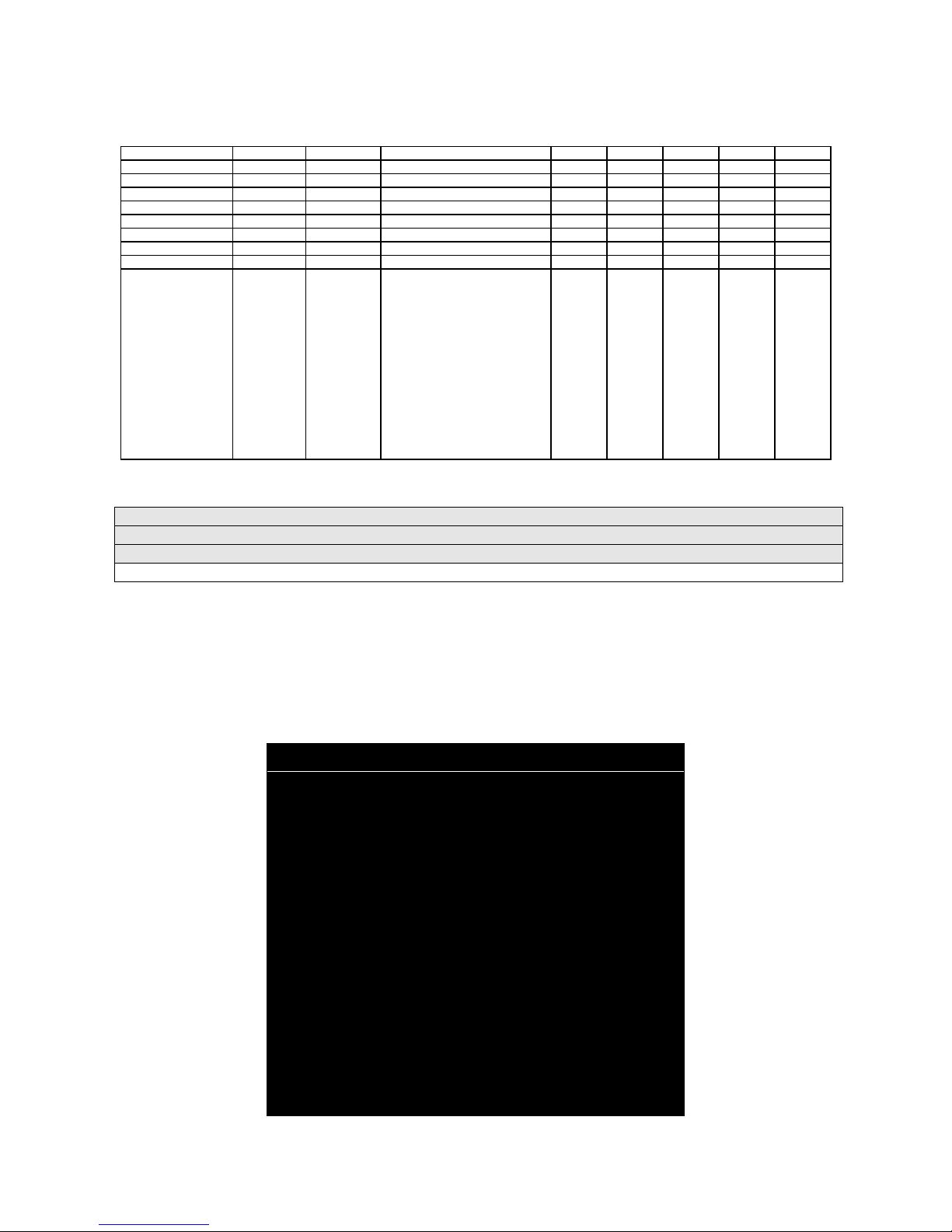
STANDARD PRICING TABLE, continued
NAME START CONTINUE CREDITS/COIN COIN 1 COIN 2 COIN 3 COIN4 BILL
UK ECA 1 1 1 1/50p, 3/£1.00 £1.00 50p 20p 10p £2.00
UK ECA 2 1 1 1/50p, 2/£1.00 £1.00 50p 20p 10p £2.00
UK ECA 3 1 1 1/30p, 2/50p, 5/£1.00 £1.00 50p 20p 10p £2.00
UK 4 1 1 1/50p, 3/£1.00 £1.00 50p
UK 5 1 1 1/50p, 2/£1.00 £1.00 50p
UK ECA 6 1 1 1/30p, 2/50p, 4/£1.00 £1.00 50p 20p 10p £2.00
UK ECA 7 1 1 3/£1.00 £1.00 50p 20p 10p £2.00
UK ECA 8 1 1 1/50p, 2/£1.00, 4/£2.00 £1.00 50p 20p 10p £2.00
USA1 2 2 1/25¢ 25¢ 25¢ $1.00
USA2 2 1 1/25¢ 25¢ 25¢ $1.00
USA3 1 1 1/25¢ 25¢ 25¢ $1.00
USA4 1 1 1/50¢, 3/$1.00 25¢ 25¢ $1.00
USA5 2 1 1/50¢, 4/$1.00 25¢ 25¢ $1.00
USA6 1 1 1/50¢ 25¢ 25¢ $1.00
USA7 1 1 1/50¢, 3/$1.00 25¢ 25¢ $1.00
USA8 2 2 1/50¢, 4/$1.00 25¢ 25¢ $1.00
USA9 3 2 1/25¢, 4/$1.00 25¢ 25¢ $1.00
USA10 3 3 1/25¢, 4/$1.00 25¢ 25¢ $1. 00
USA11 4 2 1/25¢, 4/$1.00 25¢ 25¢ $1. 00
USA12 4 3 1/25¢, 4/$1.00 25¢ 25¢ $1. 00
USA13 4 4 1/25¢, 4/$1.00 25¢ 25¢ $1. 00
USA ECA 3 3 1/25¢, 4/$1.00 $1.00 25¢ 10¢ 05¢ $1.00
Main Menu (continued)
Adjustments Menu (continued)
Pricing Menu (continued)
Current Pricing Menu
Current Pricing
Select SHOW CURRENT at the Pricing Menu. T he Current Pricing Menu is a read-only menu . Use it to
check pricing param eters f or the prici ng table your gam e is usin g. To selec t a new pr icing tab le, r eturn t o
the Pricing Menu. To invent your own pricing table, select Custom Pricing on the Pricing Menu.
Press any START button to exit from the menu.
CURRENT PRICING
LEFT SLOT UNITS
RIGHT SLOT UNITS
CENTER SLOT UNITS
EXTRA SLOT UNITS
BILL VALIDATOR UNITS
UNITS PER CREDIT
UNITS PER BONUS
MINIMUM UNITS
CREDITS TO START
CREDITS TO CONTINUE
MAX CREDITS
COINS PER BILL
XX
XX
XX
XX
XX
XX
XX
XX
XX
XX
XX
XX
PRESS ANY BUTTON TO EXIT
Diagnostic, Audit & Adjust m ent Men u Sy st em for NFL 3-23
CURRENT PRICING MENU
Page 44
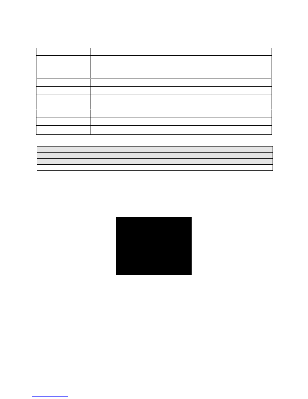
The following table clarifies Pricing Menu terms…
MENU TERM DISCUSSION
Slot Units;
Bill Validator (DBV)
Units
Units per Credit
Units per Bonus
Minimum Units
Credits to Start
Credits to Continue
Max Credits
Coins per Bill
Cyber-currency. This adjustment assigns a number of “units” to each coin mechanism
or bill acceptor. For instance, if a quarter buys 1 unit, then $1 buys 4 units. (See Coins
per Bill.) You insert a coin into a 1-unit coin acceptor. The system, due to its
programming, knows that your coin is worth one unit.
How many units equal one credit. (Units buy credit, the price of one game.)
Units awarded when a player earns a bonus.
Until this many units accumulate, the system awards no credits.
Number of games a player must purchase to begin play.
Number of games a player must purchase to resume play.
Limits the number of credits that the game will accept.
How many coins one bill is worth.
Main Menu
(continued)
Adjustments Menu
Pricing Menu
(continued)
(continued)
Custom Pricing Menu
Custom Pricing
Select CUSTOM PRICING a t the Pricing Menu. T he Custom Pricing Menu per mits you to program and
use your own pricing table. You can save several pricing schemes and chose between them as desired.
Highlight an option with any pla yer panel jo ystick. Change t he option wit h any pla yer panel button. Press
any START button to save your pricing table and exit from the menu.
CUSTOM PRICING
ADD
EXIT
CUSTOM PRICING OPENING MENU
allows you to write a new custom pricing scheme. If you choose ADD, the system directs you to…
Add
[ ] 1. Name your scheme.
[ ] 2. Program pricing information.
[ ] 3. Select the coin denomination for your scheme.
[ ] 4. Retain or alter the pricing screen message. (Later, check it in Game Mode by pressing START.)
[ ] 5. Save your pricing scheme.
[ ] 6. Use your pricing scheme by selecting it.
permits you to eliminate a single custom pricing scheme.
Delete
lets you modify a stored custom pricing scheme.
Edit
Delete,
Select
when enabled, clears all custom pricing schemes.
enables you to choose which custom pricing scheme is the active one.
Diagnostic, Audit & Adjust m ent Men u Sy st em for NFL 3-24
Page 45

Main Menu (continued)
Adjustments Menu (continued)
Pricing Menu (continued)
Custom Pricing Menu (continued)
Creating Pricing Scheme Menu
Creating Pricing Scheme
After you name your custom pricing schem e, you encounter the Creating Pricing Scheme Menu. This
menu is where you program the pricing scheme. You can save several pricing schemes and choose
between them as desired.
Highlight an option with any pla yer pa nel jo ystick . Selec t Chang e Mode with a n y player pane l button . Use
a joystick to change t he opti on. Sa ve your sett ing by pressing any pl ayer pa nel but ton. Pr ess any S TA RT
button to exit from the menu. Exiting invokes the Sel ect Currency Menu. Use this m enu to choose the
coin denomination that players will use. Exit by choosing DONE.
CREATING XXXX
LEFT UNITS
CENTER UNITS
DBV UNITS
UNITS / BONUS
CREDITS TO START
MAX CREDITS
SHOW FRACTIONS
RIGHT COUNT
EXTRA COUNT
USE STICK TO SELECT AN ITEM TO MODIFY
PRESS ANY BUTTON TO MODIFY THE ITEM
PRESS ANY START BUTTON TO SAVE AND EXIT
XX
XX
XX
XX
XX
XX
XX
XX
XX
RIGHT UNITS
EXTRA UNITS
UNITS PER CREDIT
MIN UNITS
CREDITS TO CONT.
COINS / BILL
LEFT COUNT
CENTER COUNT
DBV COUNT
CUSTOM PRICING MENU
SELECT CURRENCY
DOLLAR
POUND
GUILDER
SCHILLING
FRANC
KRONE
MARKKA
DEUTSCHE MARK
LIRE
FORINT
PESETA
YET
DONE
XX
XX
XX
XX
XX
XX
XX
XX
XX
SELECT CURRENCY MENU (PAGE 2 OF CREATING XXXX MENU)
Diagnostic, Audit & Adjust m ent Men u Sy st em for NFL 3-25
Page 46
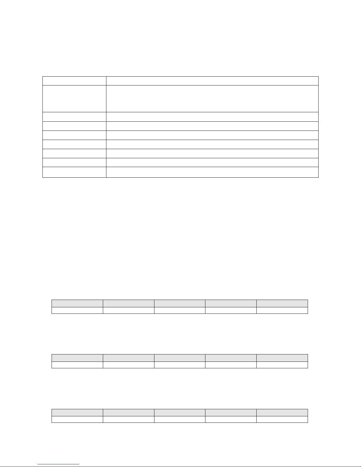
The Custom Pricing Menu employs the same terms that appear on the Current Pricing Table. See the
table below for definitions of these terms.
PRICING MENU TERMS
MENU TERM DISCUSSION
Slot Units;
Bill Validator (DBV)
Units
Units per Credit
Units per Bonus
Minimum Units
Credits to Start
Credits to Continue
Max Credits
Coins per Bill
Cyber-currency. This adjustment assigns a number of “units” to each coin mechanism
or bill acceptor. For instance, if a quarter buys 1 unit, then $1 buys 4 units. (See Coins
per Bill.) You insert a coin into a 1-unit coin acceptor. The system, due to its
programming, knows that your coin is worth one unit.
How many units equal one credit. (Units buy credit, the price of one game.)
Units awarded when a player earns a bonus.
Until this many units accumulate, the system awards no credits.
Number of games a player must purchase to begin play.
Number of games a player must purchase to resume play.
Limits the number of credits that the game will accept.
How many coins one bill is worth.
BASIC CUSTOM PRICING.
Custom pricing creates an imaginar y currency exchange. In this currency
exchange, the coins of the re alm are “units.” Think of units as a type of c yber-currenc y, useful o nly within
the game software. By inserting coins, you purchase units.
Since units are only negotiable within game software, the system stores your units for you. W hen the
system receives enough units , it buys a game for you. The price of a game is one “credit.” You can think
of credits as a second form of cyber-currency.
Even though you’ve now bought one game, you may not be able to begin playing. In many pricing
schemes, you must buy two or more credits to beg in play. The idea here is som ething like a m inimum
order of goods at a stor e. That is, th e operator c an “shrink-wrap” two or more gam es in a package. You
can’t play unless you buy the entire package.
1 / 25¢ COIN; 1 CREDIT TO START
•
.
In a simple, quart er pric ing s chem e, the pl ayer ins erts one co in t o bu y
one unit. The system exchanges that unit for one cr edit. If CREDITS T O START contains the value one,
then play commences. A dollar bill buys four units.
Left Slot Units Validator Units Units / Credit Credits to Start Coins / Bill
14114
1 / 3 X 25¢; 2 CREDITS TO START.
•
Again, assuming quarter slots, here’s one way to implement 75¢
pricing… In this schem e, each coin that the player inserts buys one unit. The system exchanges three
units for one credit. CREDITS TO START contains the value two. To play, the p layer must pay for two
credits. In this scheme, a dollar buys four units.
Left Slot Units Validator Units Units / Credit Credits to Start Coins / Bill
14324
2 / 1 COIN; 6 CREDITS TO START
•
can buy two units with one coin. The system exchanges each of these units for one credit. Notice th at
CREDITS TO START contains the value six. To play, the player must insert two more coins to pay for six
credits. Also notice that if the player pays with a bill, the system throws in an extra unit.
Left Slot Units Validator Units Units / Credit Credits to Start Coins / Bill
29164
Diagnostic, Audit & Adjust m ent Men u Sy st em for NFL 3-26
.
Now let’s consider a m ore unusual pricing schem e. Here, the player
Page 47
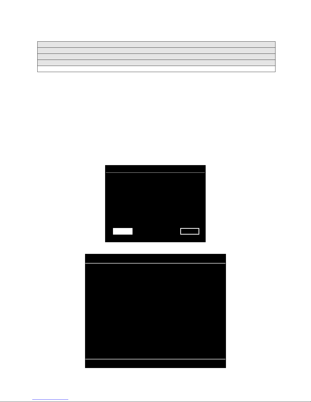
Main Menu (continued)
Adjustments Menu (continued)
Pricing Menu (continued)
Custom Pricing Menu (continued)
Current Pricing Prompt
Pricing Prompt
After you exit the Se lect Currency Menu, you encounter the Current Pr icing Prompt Menu. The Current
Pricing Prompt Menu al lo ws you to enter a brief pr ic in g or a dv er tis i ng message. The vide o g ame machine
displays your message during the Attract Mode.
Select YES at the menu’s first page. The Scr een Message Entr y Menu opens. Yo u ma y enter up to three
lines of text. Each line may include up to 32 alphanumeric characters. Here’s an example message…
1 CREDIT / 2 COINS
EAT AT JOE’S
Highlight a letter with any player panel jo ystick. Select the letter with any player panel butt on. Delete the
rightmost character of the default message b y selecting the on-screen as terisk (*). Watch the bottom of
the screen to see your message line develop. Save the entire line and proceed to the second line by
selecting the arrow (>).
CURRENT PRICING PROMPT
1 CREDIT / 2 COINS
DO YOU WANT TO CHANGE?
YES NO
CURRENT PRICING PROMPT MENU
PRICING – LINE 1
0
1
2
3
4
5
6
7
8
9
A
B
C
D
E
F
G
H
I
J
K
L
M
N
O
P
Q
R
S
T
U
V
W
X
Y
Z
/
$
✱
➨
1 CREDIT / 2 COINS
USE STICK TO MOVE / BUTTON TO SELECT
SCREEN MESSAGE ENTRY MENU (PRICING – LINE 1)
Diagnostic, Audit & Adjust m ent Men u Sy st em for NFL 3-27
Page 48
After you complete your message, you may edit it by reentering the Screen Message Entry Menu. To
reenter the menu, choose EDIT from the Custom Pricing Menu.
Main Menu (continued)
Adjustments Menu (continued)
Pricing Menu (continued)
Custom Pricing Menu (continued)
Save Pricing Scheme
Save Pricing Scheme
Exiting from the Sc reen Mess age Entr y Menu i nvokes the Save Pr icing Sc hem e Menu. The Save Pric ing
Scheme Menu allows you to save your pricing scheme.
Highlight an option with any player panel joystick. Select YES to save, or NO to delete your pricing
scheme.
DO YOU WANT TO SAVE XXXXX?
YES NO
SAVE PRICING SCHEME MENU
To use the new pricing scheme, you must now select it. The program returns you to the Custom Pricing
Menu. You’ll notice a f ew m ore entries o n the m enu. B esides ADD and EXIT , you’ll se e that you can now
EDIT or SELECT a pricing scheme.
Highlight SELECT with any player panel joystick. To use your pricing scheme, press any player panel
button. The program acknowledg es your pr ic ing s chem e choic e and retur ns you to C ustom Pric ing Menu.
Choose EXIT to return to the Pricing Menu.
CUSTOM PRICING
ADD
DELETE
EDIT
SELECT
EXIT
Diagnostic, Audit & Adjust m ent Men u Sy st em for NFL 3-28
CUSTOM PRICING OPENING MENU
Page 49
Main Menu (continued)
Adjustments Menu (continued)
Free Play Menu
Free Play
Select FREE PLAY at the Adjustm ents Menu. Free play is a useful feature f or promotions a nd long-term
testing under play conditions. Enable free play to allow players to play the game without inserting
currency. Disable free play to sell games.
Highlight an option with any player panel joystick. Select the option with any player panel button.
Main Menu (continued)
Adjustments Menu (continued)
Attract Sound Menu
Attract Sound
Select ATTRACT SOUND at the Adjustments Menu. The Attract Mode operates between games. It
attempts to lure prospective p layers into trying your game. Attract Mode sou nd may not be appropriate for
some locations. The Attract Sou nd Menu allows you to enab le or dis able the Attract Mo de sound f eature.
You can turn Attract Mode sound on or off without changing the game volume level.
Highlight an option with any player panel joystick. Select the option with any player panel button.
ENABLE ATTRACT MODE SOUNDS?
YES NO
ATTRACT SOUND MENU
NOTICE:
After you enable Attract Mode sound, you can adjust the Attract Mode
volume level. See the Main Menu.
Diagnostic, Audit & Adjust m ent Men u Sy st em for NFL 3-29
Page 50

Main Menu (continued)
Adjustments Menu (continued)
Additional Adjustments Menu
ADD I T I ONAL ADJU S T MEN TS
Select ADDITIONAL ADJUSTMENTS at the Adjustments Menu. Additional Adjustments menu items allow
you to set the game to m atch player req uirements. T hese adjustments af fect speed, chal lenge, rewards,
etc. that determine player enjoyment.
Highlight an option with any player panel joystick. Select the option with any player panel button.
ADD I T I ONAL ADJU S T MEN TS
GAME DIFFICULTY
DISCOUNT PRICE / CREDITS
CLOCK SPEED
FREE GAME – FULL 4 PLR.
FREE GAME – FULL 1 ON 1
FREE GAME – FULL V. CPU
FREE QUARTER – 4 PLR.
FREE QUARTER – 1 ON 1
FREE QUARTER – V. CPU
VIOLENCE
BAD LANGUAGE
CLEAR PLAYER RECORDS
TOURNAMENT MODE
ATTRACT MOVIE SOUND
EXIT
ADD I T I ONAL ADJU S T MEN TS ME N U
Game Difficulty
allows you to alt er the challenge that a gam e poses to players. Choos e the level that
most closely matches the players’ skills.
Discount Price / Credits
Clock Speed
alters how much game time that a pla yer can p urchas e for one cre dit. Cho ose o ne of these
adjusts the quantity of buy-in points to encourage multiple game purchases.
settings: Extra slow, slow, medium, fast or extra fast.
Free Games and Free Quarters.
Violence.
Bad Language.
Clear Player Records
Tournament Mode
Attract Movie Sound,
You can remove violence from the game without affecting other game play characteristics.
You can remove rough language without affecting other game play characteristics.
allows you to delete stored game play data.
, when enabled, adapts your game’s scoring for tournament-style play.
when enabled, all ows At tract Mo de m ovie s ound with Attr act Mode sou nd of f . T he
Use these features to provide incentives to good players.
Attract Mode movie is only one component of the Attract Mode graphics.
Diagnostic, Audit & Adjust m ent Men u Sy st em for NFL 3-30
Page 51
Main Menu (continued)
Adjustments Menu (continued)
Full Factory Restore Menu
FULL FACTORY RESTORE
Select FULL FACTOR Y RESTO RE at the A djustm ents Menu. T he Full Fac tory Restor e menu a llows you
to clear all memory counters at once.
Highlight an option with any player panel joystick. Select the option with any player panel button.
RESTORE ADJUSTMENTS & AUDITS?
YES NO
FULL FACTORY RESTORE MENU
NOTICE:
Examine and record audit information before you make changes. Once
you’ve cleared the counters, you can’t retrieve previous data from the system.
Examine and recor d utility va lues before you m ake changes. If you choose YE S, the s ystem restor es all
adjustments and audits to factory default values . This change isn’t reversi ble. The system can’t restore
the previous values. With the settings restored, the system displays the Reset Complete Menu.
AUDITS & ADJUSTMENTS RESTORED
PRESS ANY BUTTON TO EXIT
RESET COMPLETED MENU
Diagnostic, Audit & Adjust m ent Men u Sy st em for NFL 3-31
Page 52
Main Menu (continued)
Set Volume Level Menu
SET VOLUME LEVEL
Select VOLUME LEVEL at the Main Menu. The Set Volume Level Menu appears, and music plays
continuously.
Raise or lower the game’s sound level with any player panel joystick. (You can also use the volume
up/down buttons on the diag nostic switch bracket.) Save your change and return to the Main Me nu by
pressing any player panel button.
SET VOLUME LEVEL
MIN MAX
UP / DOWN TO ADJUST VOLUME
PRESS ANY BUTTON TO SET VOLUME AND EXIT
SET VOLUME LEVEL MENU
Loud games attract more player interest than games with low-level sound.
You can turn Attract Mode sound on or off without changing the game volume level. (See Adjustments.)
NOTICE:
Sound level adjustments aff ec t the vol ume of tests as well as of game play. If
you set volume levels to minim um (zero), the speakers are silent during audio tests.
We recommend setting volume levels to a moderately high value whenever you
perform sound tests . Af ter you complete tests, you m a y retur n s ou nd levels to previous
settings.
NOTICE:
You can also change t he volume le vel during G ame Mode. Pr ess VOLUME
UP or VOLUME DOWN as necessary until you achieve the desired volume. These
buttons are inside the coin door.
Diagnostic, Audit & Adjust m ent Men u Sy st em for NFL 3-32
Page 53

Main Menu (continued)
Set Attract Volume Level Menu
SET ATTRACT VOLUME LEVEL
Select ATTRACT VOLUME LEVEL at the Main Menu. You must enable Attract Mode sound before
setting the Attract Mode volume level. (You can enable Attract Sound from the Adjustments Menu.)
When you display the Set Attract Volume Level Menu, music plays continuously. Raise or lower the
game’s Attract Mode sound level with any player panel jo ystick. (You can also us e the volume up/down
buttons on the diagnostic switc h bracket.) Save your change a nd return to the Main Menu by pres sing
any player panel button. Your setting won’t affect the game play sound level.
SET ATTRACT VOLUME LEVEL
MIN MAX
UP / DOWN TO ADJUST VOLUME
PRESS ANY BUTTON TO SET VOLUME AND EXIT
SET ATTRACT VOLUME LEVEL MENU
A loud Attract Mode encourages player interest. You can turn Attract Mode sound on or off without
changing the game volume level. (See Adjustments.)
Diagnostic, Audit & Adjust m ent Men u Sy st em for NFL 3-33
Page 54
Main Menu (continued)
Utilities Menu
UTILITIES
Select UTILITIES at the Main Menu. Uti lities M enu item s allow you to c lear b ookkeeping tot als. Fr om the
Utilities Menu, you can also restore game adjustments to factory settings.
Highlight an option with any player panel joystick. Select the option with any player panel button.
UTILITIES
DUMP AUDITS
CLEAR CREDITS
CLEAR AUDITS
RESET HIGH SCORES
DEFAULT ADJUSTMENTS
FULL FACTORY RESTORE
EXIT
UTILITIES MENU
Dump Audits
allows you to send data to the game computer’s serial port. You can connect a serial
printer to make a paper record of your audit data.
Clear Credits
opens a menu that allows you to zero the gam e’s credit data. Examine and rec ord audit
information before you make changes.
Clear Audits
Reset High Scores
opens a menu that allows you to zero the game’s audit data.
permits you to delete player names and scor es that appe ar in the Attract Mo de. This
feature may be useful if players insert inappropriate language into the high score table.
Default Adjustments
Full Factory Restore
opens a menu that allows you to reset game adjustments to factory settings.
allows you to reset game adjustments and audits to factory settings.
NOTICE:
Be careful when clearing audit inf ormation. Once you clear data, you can’t
restore it.
Diagnostic, Audit & Adjust m ent Men u Sy st em for NFL 3-34
Page 55
1%$6
+2:7,0(*2/'(',7,21
1)/%
/,7=
*
2/'(',7,21
C H A P T E R
F O U R
DIAGNOSTIC, AUDIT &
ADJUSTMENT MENU SYSTEM
FOR
NOTICE:
right to make improvements in equipment as progress in engineering warrants.
NOTICE: GAME-SELECTION SWITCH.
switch 8 at DIP bank U13. Then power down an d u p aga i n. Af ter you change t he game
play, you must change game artwork.
Information in this manual is subject to change without notice. Midway reserves the
Diagnostic, Audit & Adjus tm ent Men u Sy s tem for NB A 4-1
NBA SHOWTIME
Select
NBA Showtim e
GAMES
or
NFL Blitz
by flipping
Page 56

MENU SYSTEM
WHAT IS THE MENU SYSTEM?
The game’s Menu S ystem is a series of aud iti ng, game adjustment and d ia gnostic screens. We call these
screens menus, becaus e the y pres ent opt ions in m enu-lik e list s. You c an eas il y access and appl y m enus
to optimize game performance. For instance…
•
Use game audits menus to assess game performance.
•
Use adjustment m enus to help you to customize gam e performance. For instance, you can restore
factory default game settings. You can also calibrate player controls for accuracy.
•
Use diagnostic menus to verify proper equipment operation.
ACTIVATING THE MENU SYSTEM
Open the coin door. Find the TEST MO DE switch inside. Pres s T EST MODE to invoke th e Menu System .
The game system responds by exiting G ame Mode and enter ing Diagnostic Mode. You can a lso invoke
the Menu System by turning on DIP bank U12, switch 8. (To reenter Game Mode, turn off switch 8.)
AUTOMATIC TE STS
In Diagnostic Mode, the Power-On Self-Test (POST) activates. This routine runs automatically. It can
detect faults that cause game or Menu System malf unctions. PO ST us ually tak es less than a m inute. T he
test doesn’t display anythi ng. Instead, the s ystem boot loader in dicates the soft ware revis ion num ber and
serial numbers. The system boot loader also displays a sound-loading message and other useful
information.
At the end of POST, the system displays the Control Functions Menu.
CONTROL FUNCTIONS
The Control Functions M enu is purel y informational. It appears f or five sec onds. Then the Menu System
automatically displays the Dual Game Adjustment Menu.
The Control Functions Menu introduc es the menu navigation controls. T he key point is t hat you can use
either player or diagnost ic contro ls to nav igate menus . Diagnos tic contr ol switches are part icularl y helpful
when you must troubleshoot pla yer switches. This m anual discusses the controls in m ore detail in this
chapter’s Main Menu section. Also see the page on the menu that interests you.
STICK UP/VOLUME UP – MOVE UP
STICK DOWN/VOLUME DOWN – MOVE DOWN
STICK RIGHT – MOVE RIGHT
STICK LEFT – MOVE LEFT
PUSH BUTTON/TEST BUTTON - SELECT
5 SECONDS TO DIAG ENTRY
Diagnostic, Audit & Adjus tm ent Men u Sy s tem for NB A 4-2
CONTROL FUNCTIONS MENU
Page 57

DUAL GAME ADJUSTMENT MENU
The Dual Game Adjust ment Menu is another informational, r ead-only menu. It ap pears until you choos e
to exit. This m enu reminds you that som e NBA settings also af fect NFL game pla y. Press any button to
exit to the Main Menu.
ATTENTION!
ANY CHANGES TO THE FOLLOWING ADJUSTMENTS
UPDATE BOTH NBA AND NFL
PRICING
FREE PLAY
VOLUME LEVEL
DISCOUNT PRICE / CREDITS
ATTRACT MODE SOUND ON / OFF
THIS ALSO INCLUDES DEFAULT ADJUSTME NTS
AND
FULL FACTORY RESTORE FUNCTIONS.
PRESS ANY BUTTON TO EXIT.
DUAL GAME ADJUSTMENT MENU
MAIN MENU
The Main Menu of fers you acces s to the gam e m achine’s test, b ookk eeping and pro gramm able featur es.
Game audits, adjustm ents and diagnostic s are line item s on the Main Menu . Selecting an item opens its
submenu. Every submenu presents various options that you
NBA MAIN MENU
DIAGNOSTICS
AUDITS
ADJUSTMENTS
VOLUME LEVEL
ATTRACT VOLUME LEVEL
UTILITIES
NFL MAIN MENU
EXIT TO NFL
EXIT TO NBA
MAIN MENU
MENU LAYOUT
Menus differ, but related information tends to occupy the same menu locations.
•
The block at the top, center of each menu displays the current menu title.
•
Data (menu items, video signals, statistics, reports, etc.) appears in the center of the menu.
•
Messages (explanations, control functions, revision levels) display at the bottom of the menu.
may act upon.
MENU NAVIGATION CONTROLS
Use any player panel j oystick to highlight a desire d menu item. You can only selec t one highligh ted item
at a time. To select a highlighte d item, press any pla yer panel button. Operat or control bu ttons inside t he
Diagnostic, Audit & Adjus tm ent Men u Sy s tem for NB A 4-3
Page 58
coin door serve as backup m enu navigation c ontrols. Pr ess VOLUME U P or VOLUME DOWN buttons to
highlight a menu item. Press TEST MODE to select a highlighted item.
EXIT OPTIONS
To exit the NBA menus and simultaneousl y enter the NFL menus, choose NFL MAIN MENU. To return
the game to play, high light either EX IT TO NFL or EXIT T O NBA. Your choic e determines the gam e that
will boot. Next, press any button.
NOTICE:
This manual depicts some menus as ha ving two pages. Your video game
machine may present these same menus as one-pagers. Monitor resolution affects
whether a menu has a second screen.
Main Menu (continued)
Diagnostics Menu
DIAGNOSTICS
Select DIAGNOSTICS at the Main Menu. Dia gnos t ic tests all o w you to verif y the c on d ition of the electrica l
and electronic hardware in the game.
Highlight a test with any player panel joystick. Select the option with any player panel button.
DIAGNOSTICS
MONITOR SETUP
SYSTEM INFO
SOUND SUBSYSTEM
DISK TESTS
SWITCH TESTS
DIP-SWITCH TESTS
SPEAKER TEST
EXIT
DIAGNOSTICS MENU
Diagnostic tests ass ist you in ch ecking and adj usting the gam e’s major s ystems. By running d iagnostics,
you can gain an ins igh t i nto both system hardware and g ame software. Periodically runn in g diagnostics is
a crucial part of maintaining game performance and player satisfaction. Sometimes you can improve
game performance by running a diagnostic test and making appropriate adjustments.
Diagnostic, Audit & Adjus tm ent Men u Sy s tem for NB A 4-4
Page 59
0DLQ 0HQX
FRQWLQXHG
'LDJQRVWLFV 0HQX
FRQWLQXHG
0RQLWRU 6HWXS 0HQX
MONITOR SETUP
Select MONITOR SET UP at the D iagnos tics Menu. T he Mo nitor P atterns r outine pr ov ides tes t sc reens to
verify monitor performance or make adjustments.
Highlight an option with any player panel joystick. Select the option with any player panel button.
MONITOR SETUP
COLOR BARS
CROSSHATCH
RED SCREEN
BLUE SCREEN
GREEN SCREEN
WHITE SCREEN
BLACK SCREEN
50 PCT. GRAY SCREEN
25 PCT. GRAY SCREEN
EXIT
MONITOR SETUP MENU
Color Bars
fills the screen with colored stripes . Use the co lor bars to help you to check or adjus t monitor
brightness and contrast. T he color bars also ex pose defects in horizontal lin earity. Each color bar c ons ists
of 32 intensity levels. On a properl y adjusted monitor, the top 31 of these levels are visible. Each bar
should appear sharp, c lear and dist inct from bars on either side. Incorrect a djustment c an cause mis sing
detail at the top or bottom of a bar. Bent bars indicate horizontal linearity flaws, such as pie crust,
pincushion or barrel distortion. (Correct color bar colors, left to right: Red, Green, Blue, Black, White,
Cyan, Yellow, Violet.) Set controls as follows: 1. Adjust BRIGHTNESS and CONTRAST to minimum. 2.
Turn up BRIGHTNESS until the pixels in the black stripe begin to glow (t urn dark gray). 3. Brin g up the
CONTRAST control until you can see 31 bars.
Crosshatch Patterns
fill the screen wit h a grid and a series of dots. Crossha tch Patterns help you to
check or adjust several monitor param eters: These include convergence, linearity, active viewing area
and dynamic foc us. The grid and t he dots sho uld be all wh ite in col or, with no fr inges or parallel images.
The lines should b e straight and the dots round. F or more detail on these adj ustments, consult service
literature from the monitor manufacturer.
Color Screen
tests fill the scr een with 100% of the chosen co lor at normal intensit y. The Color Screen
tests help you to check or adjust monitor intensity, black level, blanking and color purity. Each screen
should be absolutel y uniform f rom top to bottom and side to side. No retrace lines or nois e should be
visible. Color Screens may not hold their uniformity if the monitor degaussing circuit is defective.
White, Gray and Black Screens
fill the screen with black, gray or white at various intensities. These
monochrome screens help you to check or adjust monitor convergence, purity, contrast and intensity.
These screens also simplif y black level a nd color gun control settings. The s creens should be uniform
with no color tints or distortion. No retrace lines or noise should be visible.
If tests indicate a need for adjustment, use controls on the Monitor Remote Adjustment Board.
Diagnostic, Audit & Adjus tm ent Men u Sy s tem for NB A 4-5
Page 60

Main Menu (continued)
Diagnostics Menu (continued)
System Information Menu
SYSTEM INFORMATION
Select SYSTEM INFO at the Diagnostics Menu. The System Information Menu provides the current
version numbers of this game’s hardware and software. Use these numbers to describe the system
during parts replacement, service calls, etc.
Highlight an option with any player panel joystick. Select the option with any player panel button.
SYSTEM INFORMATION
MIDWAY GAMES, INC.
XXXXXXX SYSTEM
SERIAL NUMBER: XXXXXXXXX
GAME: XXXXXXXXXX
DATE OF MANUFACTURE: XX/XX/XX
PRESS ANY BUTTON TO EXIT
SYSTEM INFORMATION MENU
The System Inform ation menu reports infor mation, but doesn’t perm it you to make c hanges. T he T itle lin e
identifies the manufacturer of this game and the electronic board set used in this product. The Serial
Number, Game and Date of Manufacture identify the game name and production run.
Diagnostic, Audit & Adjus tm ent Men u Sy s tem for NB A 4-6
Page 61

Main Menu (continued)
Diagnostics Menu (continued)
Sound Subsystem Menu
SOUND SUBSYSTEM TEST
Select SOUND SUBSYSTEM at the Diagnostics Menu. Sound Subsystem Tests verify that audio
components are connected and operate properly.
Highlight an option with any player panel joystick. Select the option with any player panel button.
SOUND SUBSYSTEM TEST
BOOT VERSION: XX.XX
SDRC VERSION: XX.XX
PORT STATUS: GOOD
CHECKSUM: XXXX
SRAM: OK
DRAM: OK
TONE STATUS: GOOD
OS VERSION: XX.XX
PRESS ANY BUTTON TO EXIT
SOUND SUBSYSTEM MENU
Version, Status, Checksum and RAM Reports
are diagnostic routines. These routines analyze the
digital sound circuits and can detect sound memory problems. Test results appear as numbers or
messages. Sounds may also accompany some tests. Reports other than GOOD or OK indicate a
problem.
Diagnostic, Audit & Adjus tm ent Men u Sy s tem for NB A 4-7
Page 62

Main Menu (continued)
Diagnostics Menu (continued)
Disk Tests Menu
DISK TESTS
Select DISK TESTS at the D iagnostics M enu. Disk Tests allo w you to verif y proper opera tion of the har d
disk drive assembly.
Highlight an option with any player panel joystick. Select the option with any player panel button.
DISK TESTS
DISK INFORMATION
SEQUENTIAL READ
SEQUENTIAL CACHE READ
RANDOM READ
RANDOM CACHE READ
DATA INTEGRITY TEST
FILE SYSTEM CHECK
SURFACE SCAN
EXIT
DISK TESTS MENU
Disk Information.
The Disk Information r outine verifies the i nterface between t he CPU Board Assem bly
and hard disk drive. T he processor requests disk information. Data cannot be retrieved successfully if
there is a problem.
Sequential Read.
This routine tries to access every bit of data in the order i t is st ore d d ir ectly on the disk.
The hard disk drive media may be defective if this routine cannot be completed successfully.
Sequential Cache Read.
This routine tries to access every bit of data in the order it is stored in the
temporary disk memory cache. If this test is not successful, the memory circuits may be faulty.
Random Read.
This routine tries to access ever y bit of data in n o particular ord er directl y from the disk.
This test may detect problems with ability to position the drive heads accurately over the requested data.
Random Cache Read.
This routine tries to access every bit of data in no particular order from the
temporary disk memory cache. If the cache fails this test, memory circuits may contain a fault.
Data Integrity Test.
This test analyzes the dat a o n th e d is k drive. The test det ermines if corrupted da ta is
on the disk. Bad data can cause the program to falter even though the hard disk operates correctly.
File System Check.
Surface Scan.
This routine performs a file-by-file check of the data stored on the hard disk.
The magnetic material on the dis k can becom e dam aged, causing da ta to be unr eadabl e.
This routine locates unusable areas on the disk and marks them for future reference.
Diagnostic, Audit & Adjus tm ent Men u Sy s tem for NB A 4-8
Page 63
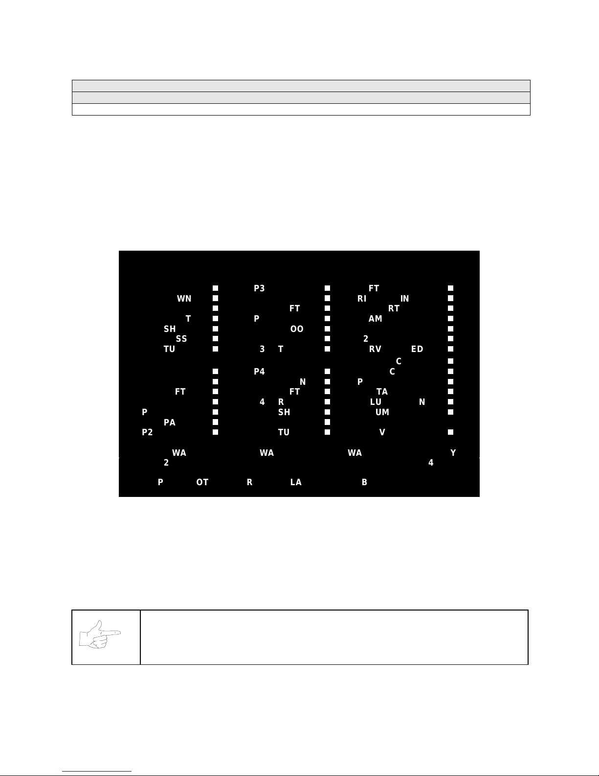
Main Menu (continued)
Diagnostics Menu (continued)
Switch Tests Menu
SWITCH TESTS
Select SWITCH TESTS at the Diagnostics Menu. Switch Tests verify proper operation of the game’s
switches, including buttons and joystick switches.
Activate each switch, and the indicator on the menu changes state. Release the switch and the indicator
returns to its previous, normally open or closed condition. You can test any combination of switches
together. To exit the test, simultaneously press the middle two control buttons inside the coin door. The
Switch Test Menu refers to these buttons as “volume buttons.”
PLAYER SWITCH INPUTS TEST
P1 UP
P1 DOWN
P1 LEFT
P1 RIGHT
P1 SHOOT
P1 PASS
P1 TURBO
P2 UP
P2 DOWN
P2 LEFT
P2 RIGHT
P2 SHOOT
P2 PASS
P2 TURBO
P1 49 WAY P2 49 WAY P3 49 WAY P4 49 WAY
24 24 24 24
PRESS BOTH PLAYER 1 AND PLAYER 2 START BUTTONS TO EXIT
P3 UP
P3 DOWN
P3 LEFT
P3 RIGHT
P3 SHOOT
P3 PASS
P3 TURBO
P4 UP
P4 DOWN
P4 LEFT
P4 RIGHT
P4 SHOOT
P4 PASS
P4 TURBO
LEFT COIN
RIGHT COIN
P1 START
SLAM/TILT
TEST
P2 START
SERVICE CREDIT
CENTER COIN
EXTRA COIN
P3 START
P4 START
VOLUME DOWN
VOLUME UP
BILL VALID.
SWITCH TEST MENU
Switches
appear on the menu as colored boxes. Red boxes indicate an open state. Green indicates
closed. Any other color indicates a fault condition. A single indication on the menu should exactly
duplicate a button or joystick change. You’ll notice a unique number for a switch recognized by game
electronics.
Use Switch Tests to locate crossed wires, intermittent conditions and stuck switches.
NOTICE:
Some switches may not be used with this game. If you can’t find one of the
listed switches, check the wiring diagram.
Diagnostic, Audit & Adjus tm ent Men u Sy s tem for NB A 4-9
Page 64
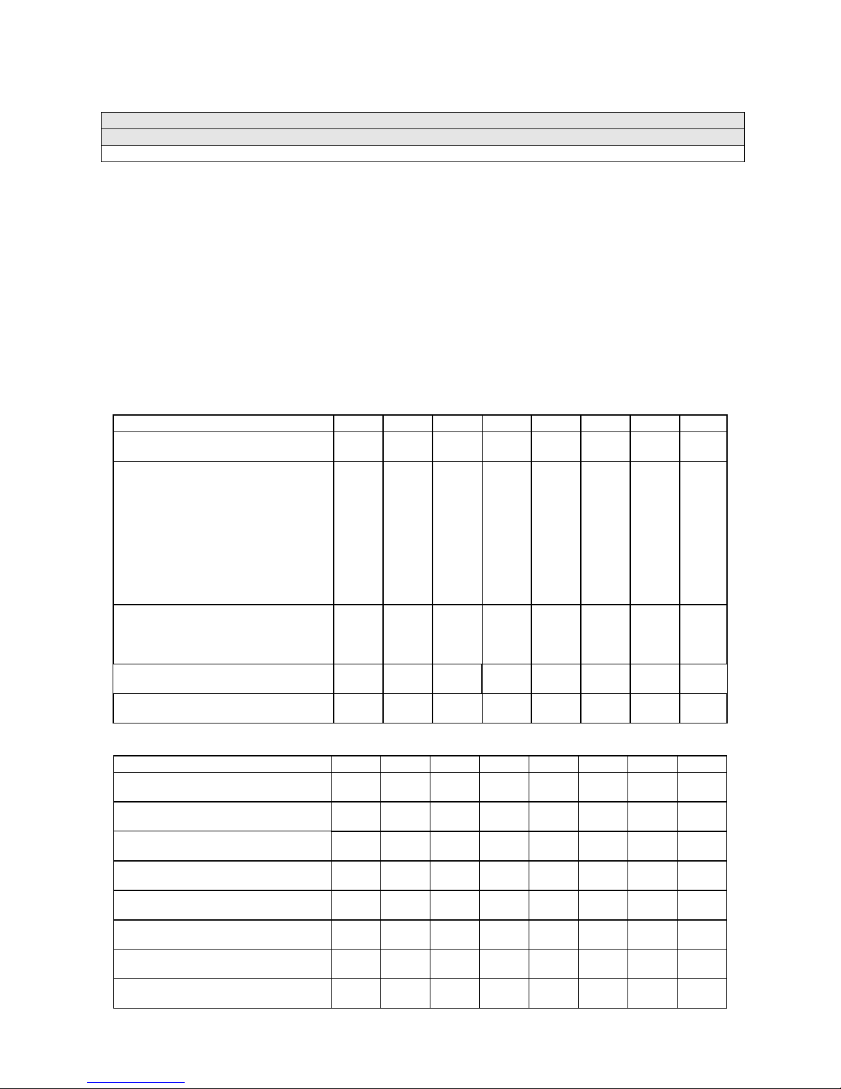
Main Menu (continued)
Diagnostics Menu (continued)
DIP Switch Tests Menu
DIP-SWITCH TESTS
Select DIP-SW ITCH T EST S at th e Di agn os tics Me nu. Two 8-position DIP s witc h ba nks reside o n th e S IO
Board. DIP-Switch Tests allow you to check the position of the 16 switches in these banks. You can
change the setting of any DIP switch without removing the circuit board cage.
The menu displays an illustration of each switch block and th e current settings. You can change DIPswitch positions with power on. Set an y switch, and t hen check the menu to verif y that the ne w setting is
enabled.
Refer to the charts for assistance in choosin g switch positions. (* in dicates factory def aults.) To exit the
DIP-switch Test, press the left control button (inside the coin door).
Game-Selection Switch .
Select NBA Showtime or NFL Blitz b y flipping switc h 8 at DIP bank U13. T hen
power down and up again. After you change the game play, you must change game artwork.
DIP Switch 1 (U13)
Coinage Control DIP Switch
CMOS
USA1 Ger1 Fr ECA1 UK1
USA2 Ger2 Fr ECA2 UK2
USA3 Ger3 Fr ECA3 UK3
USA4 Ger4 Fr ECA4 UK4
USA5 Ger5 Fr ECA5 UK5
USA9 Ger9 Fr ECA9 UK9
USA10 Ger10 Fr ECA10 UK ECA
USA ECA / Ger ECA / Fr ECA8
Free Play (All Countries)
Country USA
France
Germany
UK**
Game Selection By player
By Switch 8
Game at power up NBA Showtime
NFL Blitz
SW1 SW2 SW3 SW4 SW5 SW6 SW7 SW8
Off
On*
Off*
On
Off
On
Off
On
Off
On
On
Off*
Off
On
On
Off
Off
On
On
On
Off*
Off
Off
Off
On
On
On
On
On
Off*
On
Off
On
Off*
Off
On
On
Off*
On
**Except Free Play, wh ich is “on” for SW2 through SW6.
DIP Switch 2 (U12)
Joystick Type 8-Way
49-Way
Monitor Resolution Medium Res
Low Res
Unused --
--
Unused --
--
Unused --
--
Player Panel Type 2-Player
4-Player
Power Up Test Active
Inactive
Operating Mode Game Mode
Test Mode
SW1 SW2 SW3 SW4 SW5 SW6 SW7 SW8
Off
On*
Off*
On
Off
On
Off
On
Off
On
Off
On*
Off
On*
Off*
On
Off*
On
Diagnostic, Audit & Adjus tm ent Men u Sy s tem for NB A 4-10
Page 65
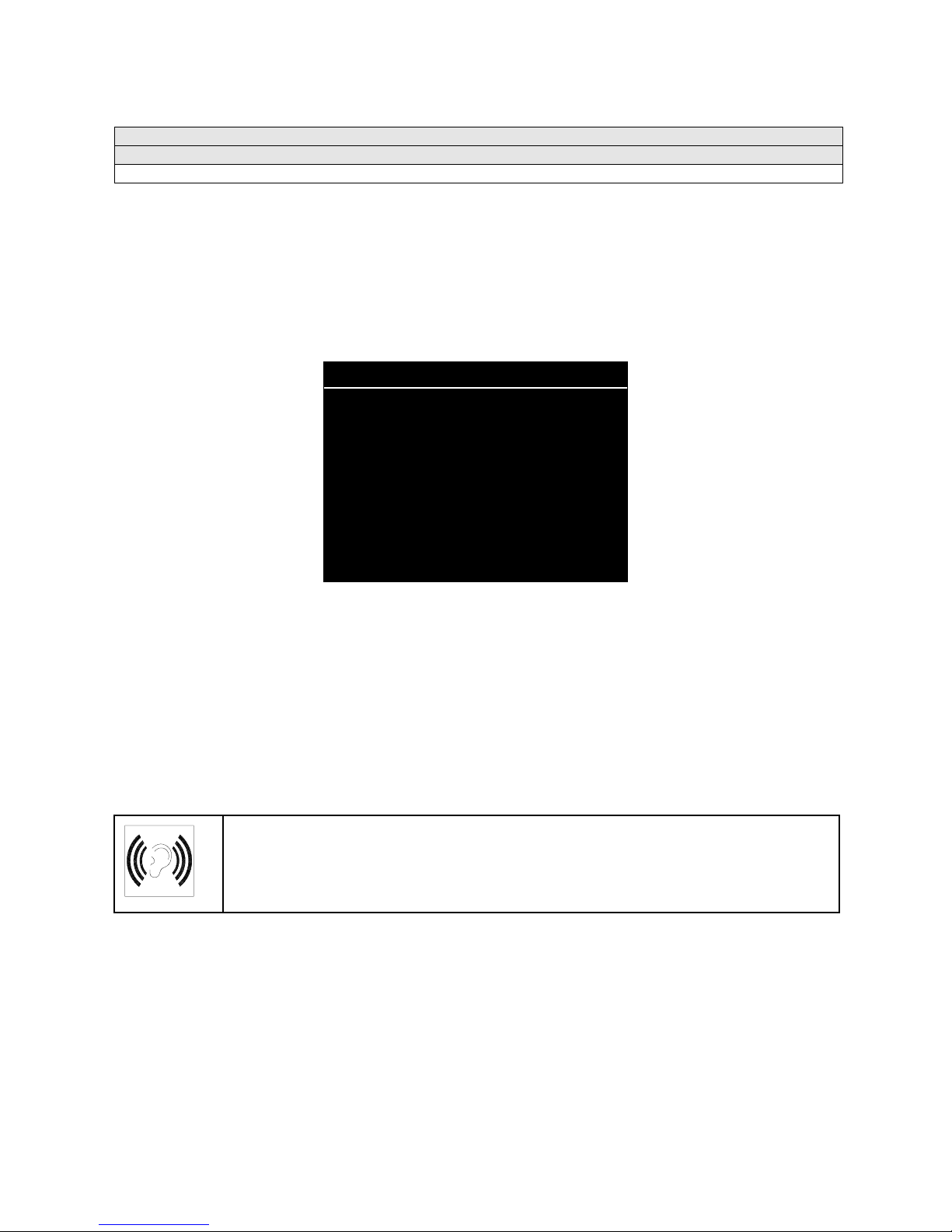
Main Menu (continued)
Diagnostics Menu (continued)
Speaker Test Menu
SPEAKER TEST
Select SPEAKER T EST at the Diagnostics Menu. The S peaker Test provides audio sig nals to test the
loudspeakers.
Use tests on the Speaker Test menu to ver ify operat ion of aud io system com ponents. Highlig ht an o ption
with any player panel joystick. Select the option with any player panel button.
SPEAKER TEST
LEFT CHANNEL
CENTER CHANNEL
RIGHT CHANNEL
100 HZ TONE
1 KHZ TONE
PLAY TUNE
EXIT
SPEAKER TEST MENU
Channel and Tone Tests.
The channel subtests employ voice announcements to verify speaker
locations. Use the 100 Hz tone to check the speakers’ bass response. Small speakers with weak
magnets or poor baffles may cause poor bass response.
Play Tune
repeats a series of game sounds. Use PLAY TUNE to check speaker operation and fidelity. If
your game has stereo speakers, run PLAY TUNE and test speaker phasing. Muddy, weak or distorted
sound during this test may indicate crossed wires or out-of-phase speaker connections. Missing sounds
may indicate audio cabling errors.
NOTICE:
Check the volume setting before testing. To test the speakers thoroughly,
increase the volume level. Before returning to Game-Over Mode, reset the volume
level to its original setting.
Diagnostic, Audit & Adjus tm ent Men u Sy s tem for NB A 4-11
Page 66
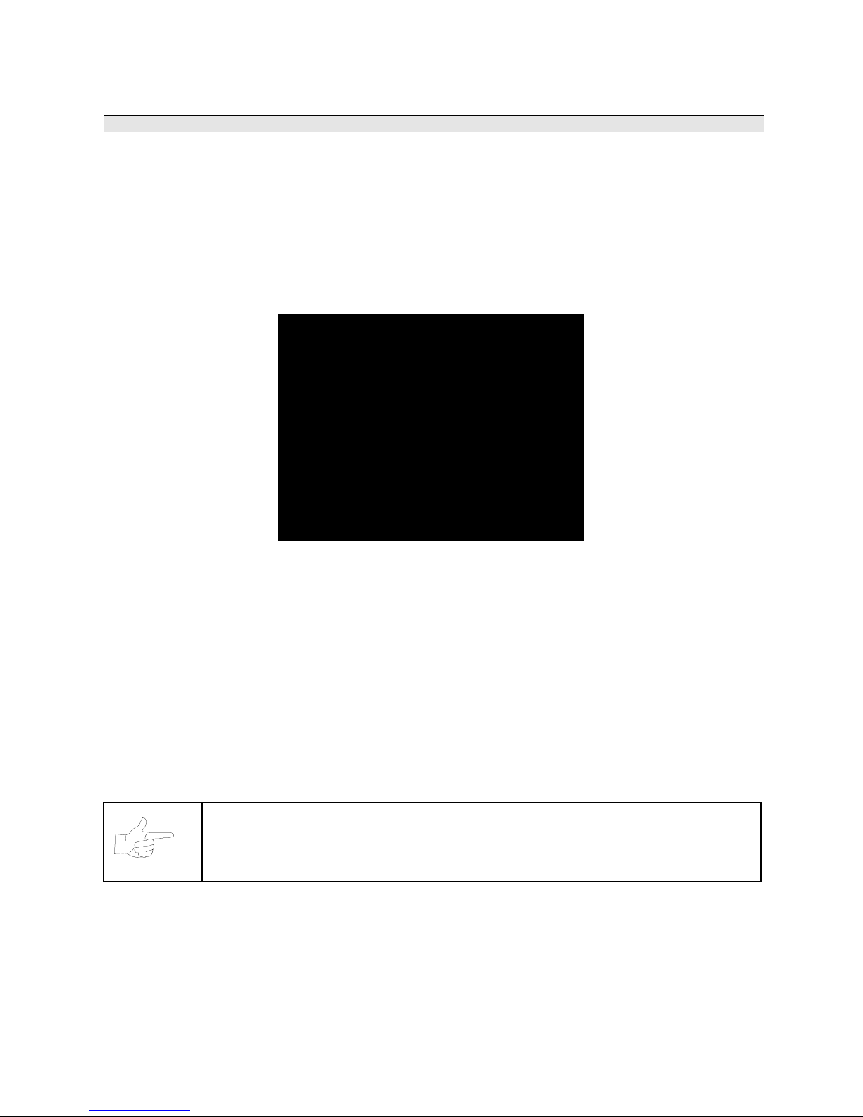
Main Menu (continued)
Audits Menu
AUDITS
Select AUDITS at the Main Menu. The Audits menus perm it you to review gam e play statistics. Additional
menus give detailed reports for each player position on game starts, ends, cabinet abuse, fault
conditions, etc.
Highlight an option with any player panel joystick. Select the o ption with any player panel button. The
menu displays a list of the statistics available to you. Select an item to view the detailed report.
AUDITS
COIN AUDITS
CREDITS AUDITS
GAME AUDITS
TEAM STATS
GAME FEATURES
EXCEPTION DUMP
CLEAR AUDITS
EXIT
AUDITS MENU
Data in the Audits menus helps you to keep records of the game’s popularity and earning potential. Use
the highlight bar to select the desired subject on the Audits Menu. Each entry on the Audits Menu is the
subject for an entire menu of bookkeeping information. On these menus, y
frequently used offensive and defensive plays, etc
.
ou can track favorite teams,
Some audits menus also include histograms. Histogram menus allow graphical analysis of statistics. This
permits visual comparisons bet ween games. Histograms have no bar graphs until the system acquires
enough data to plot.
Examine and record all game audit values before performing game service or repairs.
NOTICE:
Be careful when clearing audit information. Once you clear data, you cannot
restore it.
Diagnostic, Audit & Adjus tm ent Men u Sy s tem for NB A 4-12
Page 67

Main Menu (continued)
Audits Menu (continued)
Coin Audits Menu
COIN AUDITS
Select COIN AUDITS at the Audits Menu. The Coin Audits menu permits you to assess the currency
collection. This report m enu prese nts revenu e quantit ies and o ther im portant gam e statist ics. Coin A udits
is a read-only menu.
To exit, press any player panel button.
COIN AUDITS - PAGE: 1
LEFT SLOT COINS
RIGHT SLOT COINS
BILLS
CENTER SLOT COINS
EXTRA SLOT COINS
GAME STARTS
MID-GAME STARTS
CONTINUES
CHALLENGER ACCE PT ED
FREE QUARTERS AWARDED
FREE GAMES AWARDED
SERVICE CREDITS
UP – NEXT / BUTTON - EXIT
XXXXXXXX
XXXXXXXX
XXXXXXXX
XXXXXXXX
XXXXXXXX
XXXXXXXX
XXXXXXXX
XXXXXXXX
XXXXXXXX
XXXXXXXX
XXXXXXXX
XXXXXXXX
COIN AUDITS MENU
The Coin Audits menu reports total quantities of coins, bills or credits collected by each active device. The
menu doesn’t calculate the value of the collected currency.
This menu reports i nformation, but doesn ’t perm it you to mak e changes. To res et the coin, bill and credit
counters to zero, use the Clear Audits menu.
We recommend that you examine and record au dit information bef ore you make changes . Once you’ve
cleared the counters, you can’t retrieve the previous data from the system.
Diagnostic, Audit & Adjus tm ent Men u Sy s tem for NB A 4-13
COIN AUDITS – PAGE: 2
TOTAL PLAYS
TOTAL PAID CREDITS
TOTAL
XXXXXXX
XXXXXXX
XXXXXXX
DOWN - PREV / BUTTON - EXIT
COIN AUDITS MENU, PAGE 2
Page 68

Main Menu (continued)
Audits Menu (continued)
Credits Audits Menu
CREDITS AUDITS
Select CREDITS AUDITS at the Audits Menu. The Credits Audits menu permits you to assess the
currency collection. This report menu presents revenue quantities and other important game statistics.
Credit s Audits is a read-only menu.
To exit, press any player panel button.
CREDITS AUDITS - PAGE: 1
CREDITS AVAILABLE XXXXXXXX
PRESS ANY BUTTON TO EXIT
CREDITS AUDITS MENU
Diagnostic, Audit & Adjus tm ent Men u Sy s tem for NB A 4-14
Page 69
Main Menu (continued)
Audits Menu (continued)
Game Audits Menu
GAME AUDITS
Select GAME AUDITS a t the Audits Menu. The Gam e Audits m enus perm it you to review t he gam e play
statistics. Game Audits is a read-only menu.
To exit, press any player panel button.
GAME AUDITS - PAGE: 1
MACHINE POWER-ON
TOTAL UPTIME
TOTAL PLAYTIME
GAMES STARTED
INITIALS ENTERED
<FG> PURCHASED AT START
CREATE PLAYER SESSIONS
1 PLAYER
2 PLAYER
3 PLAYER
4 PLAYER
2P V CPU
1 QUARTER GAMES
2 QUARTER GAMES
3 QUARTER GAMES
4 QUARTER GAMES
XX
XX
XX
XX
XX
XX
XX
XX
XX
XX
XX
XX
XX
XX
XX
XX
XX
XX
XX
XX
XX
XX
WENT INTO OVERTIME 1
WENT INTO OVERTIME 2
WENT INTO OT 3
1 PLAYER FINISHES
2 PLAYER FINISHES
3 PLAYER FINISHES
4 PLAYER FINISHES
2P V CPU FINISHES
H VS H LSW’S
CPU WINS (FG)
AVG H VS H TOTAL SCORE (FG)
AVG H VS CPU TOTAL SCORE (FG) AVG
AVG H VS H WIN SCORE (FG)
AVG H VS H LOSS SCORE (FG)
BIGGEST CPU WIN MARGIN (FG)
BIGGEST CPU LOSS MARGIN (FG)
XX
XX
XX
XX
XX
XX
XX
XX
XX
XX
XX
XX
XX
XX
XX
XX
GAME AUDITS MENU
The Game Audits menu reports information, but doesn’t permit you to make changes. Examine and
record information at G AME AUDIT S before deleti ng dat a at the Clear Audits Menu. Once you’ve clea red
the counters, you can’t retrieve the previous data from the system.
GAME AUDIT MENU TERMS
TERM
AVG
CPU
<FG>, (FG)
H VS CPU
H VS H
Average
Central Processing Unit: The game
computer
Full Game
Human versus CPU: Competition that
pits players against the game computer
Human versus human: Competition
between human players
DEFINITION TERM DEFINITION
LSW
Machine
Power-On
OT
PV
Total Uptime
2PV
Your game computer’s internal
record-keeping counters
Number of power cycles (game turnons)
Overtime
Player versus…
Overall on-time for the game
computer
Two players versus…
Diagnostic, Audit & Adjus tm ent Men u Sy s tem for NB A 4-15
Page 70

Main Menu (continued)
Audits Menu (continued)
Team Stats Menu
TEAM STATS
Select TEAM STATS at the Audits Menu. The Team Stats Menu details the number of games played by
each team in the league. Team Stats is a read-only menu.
To exit, press any player panel button.
TEAM STATS – PAGE: 1
ATLANTA HAWK S
BOSTON CELTICS
CHARLOTTE HORNETS
CHICAGO BULLS
CLEVELAND CAVALIERS
DALLAS MAVERICKS
DENVER NUGGETS
DETROIT PISTONS
GOLDEN STATE WARRIORS
HOUSTON ROCKETS
INDIANAPOLIS PACERS
LOS ANGELES CLIPPERS
LOS ANGELES LAKERS
MIAMI HEAT
MILWAUKEE BUCKS
MINNESOTA TIMBERWOLVES
0%
0%
0%
0%
0%
0%
0%
0%
0%
0%
0%
0%
0%
0%
0%
0%
NEW JERSEY NETS
NEW YORK NICKS
ORLANDO MAGIC
PHILADELPHIA 76ERS
PHOENIX SUNS
PORTLAND TRAILBLAZERS
SACRAMENTO KINGS
SAN ANTONIO SPURS
SEATTLE SUPERSONICS
TORONTO RAPTORS
UTAH JAZZ
VANCOUVER GRIZZLIES
WASHINGTON WIZARDS
0%
0%
0%
0%
0%
0%
0%
0%
0%
0%
0%
0%
0%
Diagnostic, Audit & Adjus tm ent Men u Sy s tem for NB A 4-16
PRESS ANY BUTTON TO EXIT
TEAM STATS MENU
Page 71

Main Menu (continued)
Audits Menu (continued)
Game Features Menu
GAME FEATURES
Select GAME FEATURES at the Audits Menu. Game Features tracks play statistics that relate characters
in the game and game play. Game Features is a read-only menu.
To exit, press any player panel button.
GAME FEATURES – PAGE: 1
NUMBER OF PLAYER RECORDS
NUMBER OF LRU RECORDS
RECORDS FROM CREATE PLAYER
NUMBER OF PLAYER FIRE
AVG PTS PLAYER FIRE
NUMBER OF TEAM FIRE
AVG PTS TEAM FIRE
NUMBER OF ALLEY OOPS
NUMBER OF DOUBLE DUNKS
CREATP MASCOT HEADS
CREATP NBA HEADS
CREATP FEMALE HEADS
CREATP UM HEADS
CREATP MID HEADS
CREATP OTHER HEADS
CREATP DEFAULT UNIFORM
0
0
0
0
0
0
0
0
0
0
0
0
0
0
0
0
CREATP CUSTOM UNIFORM
CREATP TEAM UNIFORM
CREATP NICKNAME
CREATP AVG HEIGHT PTS
CREATP AVG WEIGHT PTS
CREATP AVG PWR PTS
CREATP AVG SPEED PTS
CREATP AVG TWOPTS PTS
CREATP AVG STEAL PTS
CREATP AVG BLOCK PTS
CREATP AVG DUNK PTS
CREATP AVG DRIBBLE PTS
PRIV1
PRIV2
PRIV3
PRIV4
PRIV5
PRIV6
PRIV7
0
0
0
0
0
0
0
0
0
0
0
0
0
0
0
0
0
0
0
Number Of Player Records.
Number Of LRU Records.
Number of player initial sets entered in CMOS RAM.
Number of record slots (space for player data) left in CMOS RAM.
Records From Create Player.
Number Of Player Fire.
Avg Pts Player Fire.
Number Of Team Fire.
Number of times a player has started on fire.
Average number of points that player scored while player was on fire.
Number of times that the team has started on fire.
Diagnostic, Audit & Adjus tm ent Men u Sy s tem for NB A 4-17
UP – NEXT / BUTTON - EXIT
GAME FEATURES MENU, PAGE 1
Number of player records produced in Create Player Mode.
Page 72

Avg Pts Team Fire.
Average number of points that the team scored while it was on fire.
Number Of Alley Oops.
Total number of alley oops performed.
Number Of Double Dunks.
Creatp Mascot Heads.
Creatp NBA Heads.
Creatp Female Heads.
Creatp UM Heads.
Creatp Mid Heads.
Creatp Other Heads.
Creatp Default Uniform.
Creatp Custom Uniform.
Creatp Team Uniform.
Creatp Nickname.
Creatp Avg Height Pts.
Creatp Avg Weight Pts.
Creatp Avg Pwr Pts.
Creatp Avg Speed Pts.
Creatp Avg TwoPts Pts.
Number of player-created characters with mascot heads.
Number of player-created characters with NBA-personality heads.
Number of player-created characters with female heads.
Number of player-created characters with Universal Studios monster heads.
Number of player-created characters with Midway Games heads.
Number of player-created characters with custom heads.
Number of player-created characters with the selected team’s uniforms.
Number of player-created characters with custom uniforms.
Number of player-created characters with specific team uniforms.
Number of player-created characters with nicknames.
Average height attribute setting.
Average weight attribute setting.
Average power attribute setting.
Average speed attribute setting.
Average two-point shot attribute setting.
Total number of double dunks performed.
Creatp Avg Steal Pts.
Creatp Avg Block Pts.
Creatp Avg Dunk Pts.
Priv1.
Number of times player-created characters include privilege 1 (a player selection).
Priv2.
Number of times player-created characters include privilege 2 (a player selection).
Priv3.
Number of times player-created characters include privilege 3 (a player selection).
Priv4.
Number of times player-created characters include privilege 4 (a player selection).
Priv5.
Number of times player-created characters include privilege 5 (a player selection).
Priv6.
Number of times player-created characters include privilege 6 (a player selection).
Priv7.
Number of times player-created characters include privilege 7 (a player selection).
Priv8.
Number of times player-created characters include privilege 8 (a player selection).
Game With Creatp.
Win V CPU With Creatp.
Win V Human With Creatp.
Tournament Games.
Timer Level.
TLF’s.
Speed at which game machine produces time-released and created characters.
A counter employed by designers (has no purpose in the field).
Average stealing attribute setting.
Average blocking attribute setting.
Average dunking attribute setting.
Number of games played with player-created characters.
Number of player-won games with player-created characters.
Number of computer-won games with player-created characters.
Number of games played in Tournament-Scoring Mode.
SBLF’s.
A counter employed by designers (has no purpose in the field).
Highlight an option with any player panel joystick. Select the option with any player panel button.
Diagnostic, Audit & Adjus tm ent Men u Sy s tem for NB A 4-18
Page 73

GAME FEATURES – PAGE: 2
PRIV4
PRIV5
PRIV6
PRIV7
PRIV8
GAME WITH CREATP
WIN V CPU WITH CREATP
WIN V HUMAN WITH CREATP
TOURNAMENT GAMES
TIMER LEVEL
TLF’S
SBLF’S
0
0
0
0
0
0
0
0
0
0
0
0
DOWN – PREV / BUTTON - EXIT
GAME FEATURES MENU, PAGE 2
Diagnostic, Audit & Adjus tm ent Men u Sy s tem for NB A 4-19
Page 74
Main Menu (continued)
Audits Menu (continued)
Exception Dump Menu
EXCEPTION DUMP
Select EXCEPTION DUMP at the Audits Menu. Game programmers use the Exception Dump Menu to
view register contents during program development. This menu has no field purpose. Exception Dump is
a read-only menu.
To exit, press any player panel button.
Main Menu (continued)
Audits Menu (continued)
Clear Audits Menu
CLEAR AUDITS
Select CLEAR AUDITS at th e Au dits M en u. The Clear Audits m enu al lo ws you to clear ind ivid ual memory
counters or to reset them all at once.
Highlight an option with any player panel joystick. Select the option with any player panel button.
CLEAR AUDITS
CLEAR COIN AUDITS
CLEAR CREDITS AUDITS
CLEAR GAME AUDITS
CLEAR TEAM STATS
CLEAR GAME FEATURES
CLEAR GAME RESETS
CLEAR EXCEPTION DUMP
CLEAR ALL
EXIT
CLEAR AUDITS MENU
You can reset any audit menu from the Clear Au dits Men u. Choose an item and z ero its c ounter. CL EAR
ALL simultaneously chan ges all audit categories to factory default values . After you’ve selected an item,
the system gives you the opportunity to escape this change. For example:
ARE YOU SURE YOU WANT TO CLEAR COIN AUDITS?
YES NO
LAST CHANCE MENU
After you’ve selected an d ver if ied a cl ear f unc tion, the values res et. The system can’t restor e the pr e vious
values. Examine and recor d uti lity values before you mak e changes.
Diagnostic, Audit & Adjus tm ent Men u Sy s tem for NB A 4-20
Page 75

Main Menu (continued)
Adjustments Menu
ADJUSTMENTS
Select ADJUSTMENTS at the Main Menu. The Adjustments menus permit you to change game
characteristics. Use these menus to optimize game performance and earnings.
Highlight an option with any player panel joystick. Select the option with any player panel button.
ADJUSTMENTS
PRICING
FREE PLAY
ATTRACT SOUND
ADDITIONAL ADJUSTMENTS
FULL FACTORY RESTORE
EXIT
ADJUSTMENTS MENU
Main Menu (continued)
Adjustments Menu (continued)
Pricing Menu
PRICING
Select PRICING at the Adjustments Menu. The Pricing menus allow you to view current settings or
change the cost of games. Custom pricing allows you to selec t the num ber of coins or credi ts requ ired f or
each game. The game restores factory default values if you exchang e the CPU Board or if the back up
battery fails.
Highlight an option with any player panel joystick. Select the option with any player panel button.
You may reset options to factory defaults or change an option af ter viewing it. W e recomm end examining
and recording pricing options before making changes.
You may save sever al custom prices and then choose be tween th em as needed. On- screen instructions
guide you through the process of creating custom price settings.
PRICING
SHOW CURRENT
NORTH AMERICA
SOUTH AMERICA
EUROPE (A-H)
EUROPE (I-U)
ASIA
AUSTRALIA
CUSTOM PRICING
EXIT
PRICING MENU
An additional box appears on screen to explain the available functions as you select each item.
Diagnostic, Audit & Adjus tm ent Men u Sy s tem for NB A 4-21
Page 76
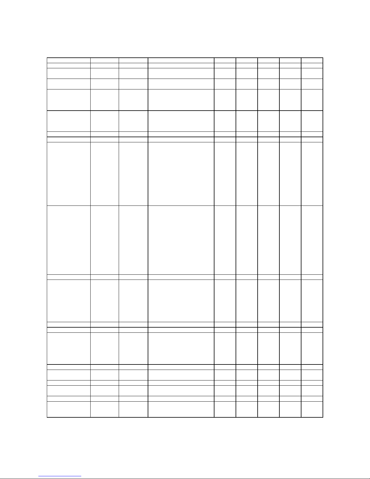
STANDARD PRICING TABLE
NAME START CONTINUE CREDITS/COIN COIN 1 COIN 2 COIN 3 COIN4 BILL
ANTILLES 2 2 1/25¢, 4/1G .25¢ 1G
AUSTRALIA 1 2 2 1/3X20¢, 2/$1.00 .20¢ $1.00
AUSTRALIA 2 1 1 1/5X20¢, 1/$1.00 .20¢ $1.00
AUSTRIA 1 2 2 1/5Sch, 2/10Sch 5 Sch 10 Sch
AUSTRIA 2 1 1 1/2X5Sch, 3/2X10Sch 5 Sch 10 Sch
BELGIUM 1 2 2 1/20BF 20BF 20BF
BELGIUM 2 2 2 3/20BF 20BF 20BF
BELGIUM 3 2 2 2/20BF 20BF 20BF
BELGIUM ECA 2 2 1/20BF 50BF 20BF 5BF
CANADA 1 2 2 1 / 2 x 25¢, 3 / $1 25¢ 25¢
CANADA 2 2 2 1 / 2 x 25¢, 3 / $1 25¢ $1.00
CANADA 3 2 2 3 / $1.00, 6 / $2.00 $1.00 $2.00
CANADA ECA 2 2 1 / 2 x 25¢, 3 / $1 25¢ $1.00 $2.00
DENMARK 2 2 3/5DKr, 7/10DKr 5DKr 10DKr
FINLAND 2 2 1/1Fmk 1Fmk 5Fmk
FRANCE 1 2 2 2/5Fr, 5/10Fr 5Fr 10Fr
FRANCE 2 2 1 2/5Fr, 4/10Fr 5Fr 10Fr
FRANCE 3 2 1 1/5Fr, 3/10Fr 5Fr 10Fr
FRANCE 4 2 1 1/5Fr, 2/10Fr 5Fr 10Fr
FRANCE 5 2 1 2/5Fr, 5/10Fr, 11/2 X 10Fr 5Fr 10Fr
FRANCE 6 2 1 2/5Fr, 4/10Fr, 9/2 X 10Fr 5Fr 10Fr
FRANCE 7 2 1 1/5Fr, 3/10Fr, 7/2 X 10Fr 5Fr 10Fr
FRANCE 8 2 1 1/5Fr, 2/10Fr, 5/2 X 10Fr 5Fr 10Fr
FRANCE 9 2 1 1/3 X 1Fr, 2/5Fr 1Fr 5Fr
FRANCE 10 2 1 1/2 X 1Fr, 3/5Fr 1Fr 5F r
FRANCE 11 2 1 1/3 X 1Fr, 2/5Fr, 5/2 X 5Fr 1Fr 5Fr
FRANCE 12 2 1 1/2 X 1Fr, 3/5Fr, 7/2 X 5Fr 1Fr 5Fr
FRANCE ECA 1 1 1 2/5Fr, 5/10Fr 1Fr 5Fr 10Fr 20Fr
FRANCE ECA 2 1 1 2/5Fr, 4/10Fr 1Fr 5Fr 10Fr 20Fr
FRANCE ECA 3 1 1 1/5Fr, 3/10Fr 1Fr 5Fr 10Fr 20Fr
FRANCE ECA 4 1 1 1/5Fr, 2/10Fr 1Fr 5Fr 10Fr 20Fr
FRANCE ECA 5 1 1 2/5Fr, 5/10Fr, 11/2 X 10Fr 1Fr 5Fr 10Fr 20Fr
FRANCE ECA 6 1 1 2/5Fr, 4/10Fr, 9/2 X 10Fr 1Fr 5Fr 10Fr 20Fr
FRANCE ECA 7 1 1 1/5Fr, 3/10Fr, 7/2 X 10Fr 1Fr 5Fr 10Fr 20Fr
FRANCE ECA 8 1 1 1/5Fr, 2/10Fr, 5/2 X 10Fr 1Fr 5Fr 10Fr 20Fr
FRANCE ECA 9 1 1 1/3 X 1Fr, 2/5Fr 1Fr 5Fr 10Fr 20Fr
FRANCE ECA 10 1 1 1/2 X 1Fr, 3/5F r 1Fr 5Fr 10Fr 20Fr
FRANCE ECA 11 1 1 1/3 X 1Fr, 2/5 F r, 5/10 F r 1Fr 5Fr 10Fr 20Fr
FRANCE ECA 12 1 1 1/2 X 1Fr, 3/5 F r, 7/10 F r 1Fr 5Fr 10Fr 20Fr
FRANCE ECA 13 1 1 1/10Fr, 2/20Fr, 4/30Fr 1Fr 5Fr 10Fr 20Fr
FREE PLAY -- -- -- None None None None None
GERMANY 1 2 2 1/1DM, 6/5DM 1DM 5DM
GERMANY 2 2 1 1/1DM, 7/5DM 1DM 5DM
GERMANY 3 2 1 1/1DM, 8/5DM 1DM 5DM
GERMANY 4 2 1 1/1DM, 5/5DM 1DM 5DM
GERMANY 5 2 1 1/1DM, 6/5DM 1DM 5DM
GERMANY ECA 1 2 2 1/1DM, 2/2DM, 6/5DM 1DM 2DM 5DM
GERMANY ECA 2 2 1 1/1DM, 2/2DM, 6/5DM 1DM 2DM 5DM
GERMANY ECA 3 1 1 1/1DM, 2/2DM, 6/5DM 1DM 2DM 5DM
HUNGARY 2 2 1/2 X10 Ft, 3/2X20Ft 10Ft 20Ft
ITALY 2 2 1/500LIt 500LIt 500LIt
JAPAN 1 2 2 1/100Yen 100 100
JAPAN 2 2 2 2/100Yen 100 100
JAPAN 3 1 1 1/100Yen 100 100
JAPAN 4 1 1 2/100Yen 100 100
JAPAN 5 1 1 4/100Yen 100 100
JAPAN 6 1 1 1/2X100Yen 100 100
NETHERLANDS 2 2 1/1HFI, 3/2.5HF I 1HFI 2.5HFI
NEW ZEALAND 1 1 1 1/$1 $1 $2
NEW ZEALAND 2 1 1 2/$1 $1 $2
NORWAY 2 2 3/5NKr, 6/10NKr 5NKr 10NKr
SPAIN 1 2
SPAIN 2 2 2 1/100Pta, 5/500Pta 100Pta 500Pta
SWEDEN 2 2 1/3X1SKr, 2/5SKr 1SKr 5SKr
SWITZERLAND 1 2 2 1/1SFr, 6/5SFr 1SFr 5SFr
SWITZERLAND 2 2 2 1/1SFr, 7/5SFr 1SFr 5SFr
SWITZERLAND 3 2 2 1/1SFr, 8/5SFr 1SFr 5SFr
2 1/100Pta, 6/500Pta
100Pta 500Pta
(Table continues on next page)
Diagnostic, Audit & Adjus tm ent Men u Sy s tem for NB A 4-22
Page 77
STANDARD PRICING TABLE, continued
NAME START CONTINUE CREDITS/COIN COIN 1 COIN 2 COIN 3 COIN4 BILL
UK ECA 1 1 1 1/50p, 3/£1.00 £1.00 50p 20p 10p £2.00
UK ECA 2 1 1 1/50p, 2/£1.00 £1.00 50p 20p 10p £2.00
UK ECA 3 1 1 1/30p, 2/50p, 5/£1.00 £1.00 50p 20p 10p £2.00
UK 4 1 1 1/50p, 3/£1.00 £1.00 50p
UK 5 1 1 1/50p, 2/£1.00 £1.00 50p
UK ECA 6 1 1 1/30p, 2/50p, 4/£1.00 £1.00 50p 20p 10p £2.00
UK ECA 7 1 1 3/£1.00 £1.00 50p 20p 10p £2.00
UK ECA 8 1 1 1/50p, 2/£1.00, 4/£2.00 £1.00 50p 20p 10p £2.00
USA1 2 2 1/25¢ 25¢ 25¢ $1.00
USA2 2 1 1/25¢ 25¢ 25¢ $1.00
USA3 1 1 1/25¢ 25¢ 25¢ $1.00
USA4 1 1 1/50¢, 3/$1.00 25¢ 25¢ $1.00
USA5 2 1 1/50¢, 4/$1.00 25¢ 25¢ $1.00
USA6 1 1 1/50¢ 25¢ 25¢ $1.00
USA7 1 1 1/50¢, 3/$1.00 25¢ 25¢ $1.00
USA8 2 2 1/50¢, 4/$1.00 25¢ 25¢ $1.00
USA9 3 2 1/25¢, 4/$1.00 25¢ 25¢ $1.00
USA10 3 3 1/25¢, 4/$1.00 25¢ 25¢ $1. 00
USA11 4 2 1/25¢, 4/$1.00 25¢ 25¢ $1. 00
USA12 4 3 1/25¢, 4/$1.00 25¢ 25¢ $1. 00
USA13 4 4 1/25¢, 4/$1.00 25¢ 25¢ $1. 00
USA ECA 3 3 1/25¢, 4/$1.00 $1.00 25¢ 10¢ 05¢ $1.00
Main Menu (continued)
Adjustments Menu (continued)
Pricing Menu (continued)
Current Pricing Menu
Current Pricing
Select SHOW CURRENT at the Pricing Menu. T he Current Pricing Menu is a read-only menu . Use it to
check pricing param eters f or the prici ng table your gam e is usin g. To selec t a new pr icing tab le, r eturn t o
the Pricing Menu. To invent your own pricing table, select Custom Pricing on the Pricing Menu.
Press any START button to exit from the menu.
CURRENT PRICING
LEFT SLOT UNITS
RIGHT SLOT UNITS
CENTER SLOT UNITS
EXTRA SLOT UNITS
BILL VALIDATOR UNITS
UNITS PER CREDIT
UNITS PER BONUS
MINIMUM UNITS
CREDITS TO START
CREDITS TO CONTINUE
MAX CREDITS
COINS PER BILL
XX
XX
XX
XX
XX
XX
XX
XX
XX
XX
XX
XX
Diagnostic, Audit & Adjus tm ent Men u Sy s tem for NB A 4-23
CURRENT PRICING MENU
Page 78
The following table clarifies Pricing Menu terms…
MENU TERM DISCUSSION
Slot Units;
Bill Validator (DBV)
Units
Units per Credit
Units per Bonus
Minimum Units
Credits to Start
Credits to Continue
Max Credits
Coins per Bill
Cyber-currency. This adjustment assigns a number of “units” to each coin mechanism
or bill acceptor. For instance, if a quarter buys 1 unit, then $1 buys 4 units. (See Coins
per Bill.) You insert a coin into a 1-unit coin acceptor. The system, due to its
programming, knows that your coin is worth one unit.
How many units equal one credit. (Units buy credit, the price of one game.)
Units awarded when a player earns a bonus.
Until this many units accumulate, the system awards no credits.
Number of games a player must purchase to begin play.
Number of games a player must purchase to resume play.
Limits the number of credits that the game will accept.
How many coins one bill is worth.
Main Menu
(continued)
Adjustments Menu
Pricing Menu
(continued)
(continued)
Custom Pricing Menu
Custom Pricing
Select CUSTOM PRICING a t the Pricing Menu. T he Custom Pricing Menu per mits you to program and
use your own pricing table. You can save several pricing schemes and chose between them as desired.
Highlight an option with any pla yer panel jo ystick. Change t he option wit h any pla yer panel button. Press
any START button to save your pricing table and exit from the menu.
CUSTOM PRICING
ADD
EXIT
CUSTOM PRICING OPENING MENU
allows you to write a new custom pricing scheme. If you choose ADD, the system directs you to…
Add
[ ] 1. Name your scheme.
[ ] 2. Program pricing information.
[ ] 3. Select the coin denomination for your scheme.
[ ] 4. Retain or alter the pricing screen message. (Later, check it in Game Mode by pressing START.)
[ ] 5. Save your pricing scheme.
[ ] 6. Use your pricing scheme by selecting it.
permits you to eliminate a single custom pricing scheme.
Delete
lets you modify a stored custom pricing scheme.
Edit
Delete,
Select
when enabled, clears all custom pricing schemes.
enables you to choose which custom pricing scheme is the active one.
Diagnostic, Audit & Adjus tm ent Men u Sy s tem for NB A 4-24
Page 79

Main Menu (continued)
Adjustments Menu (continued)
Pricing Menu (continued)
Custom Pricing Menu (continued)
Creating Pricing Scheme Menu
Creating Pricing Scheme
After you name your custom pricing schem e, you encounter the Creating Pricing Scheme Menu. This
menu is where you program the pricing scheme. You can save several pricing schemes and choose
between them as desired.
Highlight an option with any pla yer pa nel jo ystick . Select Chang e Mode with a ny pla yer pa nel bu tton. Us e
a joystick to change t he opti on. Sa ve your sett ing b y pressing a ny pl ayer pa nel but ton. Pr ess a ny ST ART
button to exit from the menu. Exiting invokes the Sel ect Currency Menu. Use this m enu to choose the
coin denomination that players will use. Exit by choosing DONE.
CREATING XXXX
LEFT UNITS
CENTER UNITS
DBV UNITS
UNITS / BONUS
CREDITS TO START
MAX CREDITS
SHOW FRACTIONS
RIGHT COUNT
EXTRA COUNT
USE STICK TO SELECT AN ITEM TO MODIFY
PRESS ANY BUTTON TO MODIFY THE ITEM
PRESS ANY START BUTTON TO SAVE AND EXIT
XX
XX
XX
XX
XX
XX
XX
XX
XX
RIGHT UNITS
EXTRA UNITS
UNITS PER CREDIT
MIN UNITS
CREDITS TO CONT.
COINS / BILL
LEFT COUNT
CENTER COUNT
DBV COUNT
CUSTOM PRICING MENU
SELECT CURRENCY
DOLLAR
POUND
GUILDER
SCHILLING
FRANC
KRONE
MARKKA
DEUTSCHE MARK
LIRE
FORINT
PESETA
YET
DONE
XX
XX
XX
XX
XX
XX
XX
XX
XX
SELECT CURRENCY MENU (PAGE 2 OF CREATING XXXX MENU)
Diagnostic, Audit & Adjus tm ent Men u Sy s tem for NB A 4-25
Page 80
The Custom Pricing Menu employs the same terms that appear on the Current Pricing Table. See the
table below for definitions of these terms.
PRICING MENU TERMS
MENU TERM DISCUSSION
Slot Units;
Bill Validator (DBV)
Units
Units per Credit
Units per Bonus
Minimum Units
Credits to Start
Credits to Continue
Max Credits
Coins per Bill
Cyber-currency. This adjustment assigns a number of “units” to each coin mechanism
or bill acceptor. For instance, if a quarter buys 1 unit, then $1 buys 4 units. (See Coins
per Bill.) You insert a coin into a 1-unit coin acceptor. The system, due to its
programming, knows that your coin is worth one unit.
How many units equal one credit. (Units buy credit, the price of one game.)
Units awarded when a player earns a bonus.
Until this many units accumulate, the system awards no credits.
Number of games a player must purchase to begin play.
Number of games a player must purchase to resume play.
Limits the number of credits that the game will accept.
How many coins one bill is worth.
BASIC CUSTOM PRICING.
Custom pricing creates an imaginar y currency exchange. In this currency
exchange, the coins of the re alm are “units.” Think of units as a type of c yber-currenc y, useful o nly within
the game software. By inserting coins, you purchase units.
Since units are only negotiable within game software, the system stores your units for you. W hen the
system receives enough units , it buys a game for you. The price of a game is one “credit.” You can think
of credits as a second form of cyber-currency.
Even though you’ve now bought one game, you may not be able to begin playing. In many pricing
schemes, you must buy two or more credits to beg in play. The idea here is som ething like a m inimum
order of goods at a store. That is, the operator c an “shrink-wrap” two or more games in a package. You
can’t play unless you buy the entire package.
1 / 25¢ COIN; 1 CREDIT TO START
•
.
In a simple, quart er pric ing s chem e, the pl ayer ins erts one co in t o bu y
one unit. The system exchanges that unit for one cr edit. If CREDITS T O START contains the value one,
then play commences. A dollar bill buys four units.
Left Slot Units Validator Units Units / Credit Credits to Start Coins / Bill
14114
1 / 3 X 25¢; 2 CREDITS TO START.
•
Again, assuming quarter slots, here’s one way to implement 75¢
pricing… In this schem e, each coin that the player inserts buys one unit. The system exchanges three
units for one credit. CREDITS TO START contains the value two. To play, the p layer must pay for two
credits. In this scheme, a dollar buys four units.
Left Slot Units Validator Units Units / Credit Credits to Start Coins / Bill
14324
2 / 1 COIN; 6 CREDITS TO START
•
can buy two units with one coin. The system exchanges each of these units for one credit. Notice th at
CREDITS TO START contains the value six. To play, the player must insert two more coins to pay for six
credits. Also notice that if the player pays with a bill, the system throws in an extra unit.
Left Slot Units Validator Units Units / Credit Credits to Start Coins / Bill
29164
Diagnostic, Audit & Adjus tm ent Men u Sy s tem for NB A 4-26
.
Now let’s consider a m ore unusual pricing schem e. Here, the player
Page 81
Main Menu (continued)
Adjustments Menu (continued)
Pricing Menu (continued)
Custom Pricing Menu (continued)
Current Pricing Prompt
Pricing Prompt
After you exit the Se lect Currency Menu, you encounter the Current Pr icing Prompt Menu. The Current
Pricing Prompt Menu al lo ws you to enter a brief pr ic in g or a dv er tis i ng message. The vide o g ame machine
displays your message during the Attract Mode.
Select YES at the menu’s first page. The Scr een Message Entr y Menu opens. Yo u ma y enter up to three
lines of text. Each line may include up to 32 alphanumeric characters. Here’s an example message…
1 CREDIT / 2 COINS
EAT AT JOE’S
Highlight a letter with any player panel jo ystick. Select the letter with any player panel butt on. Delete the
rightmost character of the default message b y selecting the on-screen as terisk (*). Watch the bottom of
the screen to see your message line develop. Save the entire line and proceed to the second line by
selecting the arrow (>).
CURRENT PRICING PROMPT
1 CREDIT / 2 COINS
DO YOU WANT TO CHANGE?
YES NO
CURRENT PRICING PROMPT MENU
PRICING – LINE 1
0
1
2
3
4
5
6
7
8
9
A
B
C
D
E
F
G
H
I
J
K
L
M
N
O
P
Q
R
S
T
U
V
W
X
Y
Z
/
$
✱
➨
1 CREDIT / 2 COINS
USE STICK TO MOVE / BUTTON TO SELECT
SCREEN MESSAGE ENTRY MENU (PRICING – LINE 1)
Diagnostic, Audit & Adjus tm ent Men u Sy s tem for NB A 4-27
Page 82
After you complete your message, you may edit it by reentering the Screen Message Entry Menu. To
reenter the menu, choose EDIT from the Custom Pricing Menu.
Main Menu (continued)
Adjustments Menu (continued)
Pricing Menu (continued)
Custom Pricing Menu (continued)
Save Pricing Scheme
Save Pricing Scheme
Exiting from the Sc reen Mess age Entr y Menu i nvokes the Save Pr icing Sc hem e Menu. The Save Pric ing
Scheme Menu allows you to save your pricing scheme.
Highlight an option with any player panel joystick. Select YES to save, or NO to delete your pricing
scheme.
DO YOU WANT TO SAVE XXXXX?
YES NO
SAVE PRICING SCHEME MENU
To use the new pricing scheme, you must now select it. The program returns you to the Custom Pricing
Menu. You’ll notice a f ew m ore entries o n the m enu. B esides ADD and EXIT , you’ll se e that you can no w
EDIT or SELECT a pricing scheme.
Highlight SELECT with any player panel joystick. To use your pricing scheme, press any player panel
button. The program acknowledg es your pr ic ing s chem e choic e and retur ns you to C ustom Pric ing Me nu.
Choose EXIT to return to the Pricing Menu.
CUSTOM PRICING
ADD
DELETE
EDIT
SELECT
EXIT
Diagnostic, Audit & Adjus tm ent Men u Sy s tem for NB A 4-28
CUSTOM PRICING OPENING MENU
Page 83
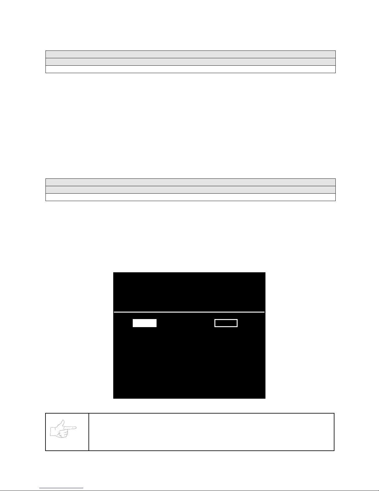
Main Menu (continued)
Adjustments Menu (continued)
Free Play Menu
Free Play
Select FREE PLA Y at the Adjustm ents Menu. F ree Play is a useful featur e for prom otions and lo ng-term
testing under play conditions. Enable Free Play to allow players to play the game without inserting
currency. Disable Free Play to sell games.
Highlight an option with any player panel joystick. Select the option with any player panel button.
Main Menu (continued)
Adjustments Menu (continued)
Attract Sound Menu
Attract Sound
Select ATTRACT SOUND at the Adjustments Menu. The Attract Mode operates between games. It
attempts to lure prospective p layers into trying your game. Attract Mode sou nd may not be appropriate for
some locations. The Attract Sou nd Menu allows you to enab le or dis able the Attract Mo de sound f eature.
You can turn Attract Mode sound on or off without changing the game volume level.
Highlight an option with any player panel joystick. Select the option with any player panel button.
ENABLE ATTRACT MODE SOUNDS?
YES NO
ATTRACT SOUND MENU
NOTICE:
After you enable Attract Mode sound, you can adjust the Attract Mode
volume level. See the Main Menu.
Diagnostic, Audit & Adjus tm ent Men u Sy s tem for NB A 4-29
Page 84

Main Menu (continued)
Adjustments Menu (continued)
Additional Adjustments Menu
ADD I T I ONAL ADJU S T MEN TS
Select ADDITIONAL ADJUSTMENTS at the Adjustments Menu. Additional Adjustments menu items allow
you to set the game to m atch player req uirements. T hese adjustments af fect speed, chal lenge, rewards,
etc. that determine player enjoyment.
Highlight an option with any player panel joystick. Select the option with any player panel button.
ADD I T I ONAL ADJU S T MEN TS
GAME DIFFICULTY
DISCOUNT PRICE / CREDITS
CLOCK SPEED
FREE GAME – FULL 4 PLR.
FREE GAME – FULL 1 ON 1
FREE GAME – FULL V. CPU
FREE QUARTER – FULL 4 PLR.
FREE QUARTER – FULL 1 ON 1
FREE QUARTER – FULL V. CPU
CLEAR PLAYER RECORDS
CLEAR WORLD RECORDS
PLAYER HEAD SIZE
TOURNAMENT MODE
COMPUTER ASSISTANCE
ATTRACT MOVIE SOUND
EXIT
ADD I T I ONAL ADJU S T MEN TS ME N U
Game Difficulty
allows you to alt er the challenge that a gam e poses to players. Choos e the level that
most closely matches the players’ skills.
Discount Price / Credits
Clock Speed
alters how much game time that a pla yer can p urchas e for one cre dit. Cho ose o ne of these
adjusts the quantity of buy-in points to encourage multiple game purchases.
settings: Extra slow, slow, medium, fast or extra fast.
Free Game,
when enabled, allows the pr ogram to award a free game. The fr ee game may be a four-
player or a one-on-one game. The free game may also involve competition against the game computer.
Free Quarter.
The program divides games into quarters, as in NBA rules. The Free Quarter feature,
when enabled, allows the program to award a free game quarter. The free quarter may be a four-player or
a one-on-one quarter. The free quarter may also involve competition against the game computer.
Clear Player Records
allows you to zero out game play data. Examine and record this information
before you clear it. Once you’ve cleared player records, you can’t retrieve the previous data.
Clear World Records
allows you to zero out world record data. Examine and record this information
before you clear it. Once you’ve cleared player records, you can’t retrieve the previous data.
Player Head Size
allows you to alter the head size of on-screen characters. This feature determines
whether the characters appear more lifelike, or more like caricatures. Choose “normal” or “big.”
Tournament Mode,
when enabled, adapts your game’s scoring for tournament-style play.
Diagnostic, Audit & Adjus tm ent Men u Sy s tem for NB A 4-30
Page 85
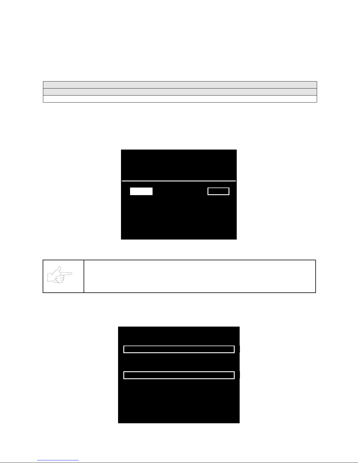
Computer Assistance,
when enabled, permits the game computer to aid players in play action.
Attract Movie Sound,
when enabled, all ows At tract Mo de m ovie s ound with Attr act Mod e sou nd of f . T he
Attract Mode movie is only one component of the Attract Mode graphics.
Main Menu (continued)
Adjustments Menu (continued)
Full Factory Restore Menu
FULL FACTORY RESTORE
Select FULL FACTOR Y RESTO RE at the A djustm ents Menu. T he Full F actory Rest ore menu a llows you
to clear all memory counters at once.
Highlight an option with any player panel joystick. Select the option with any player panel button.
RESTORE ADJUSTMENTS & AUDITS?
YES NO
FULL FACTORY RESTORE MENU
NOTICE:
Examine and record audit information before you make changes. Once
you’ve cleared the counters, you can’t retrieve previous data from the system.
Examine and record utilit y values before you make changes. If you choose YES, the system restores all
adjustments and audits to factory default values . This change isn’t reversi ble. The system can’t restore
the previous values. With the settings restored, the system displays the Reset Complete Menu.
AUDITS & ADJUSTMENTS RESTORED
PRESS ANY BUTTON TO EXIT
Diagnostic, Audit & Adjus tm ent Men u Sy s tem for NB A 4-31
RESET COMPLETED MENU
Page 86
Main Menu (continued)
Set Volume Level Menu
SET VOLUME LEVEL
Select VOLUME LEVEL at the Main Menu. The Set Volume Level Menu appears, and music plays
continuously.
Raise or lower the game’s sound level with any player panel joystick. (You can also use the volume
up/down buttons on the diag nostic switch bracket.) Save your change and return to the Main Me nu by
pressing any player panel button.
SET VOLUME LEVEL
MIN MAX
UP / DOWN TO ADJUST VOLUME
PRESS ANY BUTTON TO SET VOLUME AND EXIT
SET VOLUME LEVEL MENU
Loud games attract more player interest than games with low-level sound.
You can turn Attract Mode sound on or off without changing the game volume level. (See Adjustments.)
NOTICE:
Sound level adjustments aff ec t the vol ume of tests as well as of game play. If
you set volume levels to minim um (zero), the speakers are silent during audio tests.
We recommend setting volume levels to a moderately high value whenever you
perform sound tests . Af ter you complete tests, you m a y retur n s ou nd levels to previous
settings.
NOTICE:
You can also change t he volume le vel during G ame Mode. Pr ess VOLUME
UP or VOLUME DOWN as necessary until you achieve the desired volume. These
buttons are inside the coin door.
Diagnostic, Audit & Adjus tm ent Men u Sy s tem for NB A 4-32
Page 87

Main Menu (continued)
Set Attract Volume Level Menu
SET ATTRACT VOLUME LEVEL
Select ATTRACT VOLUME LEVEL at the Main Menu. You must enable Attract Mode sound before
setting the Attract Mode volume level. (You can enable Attract Sound from the Adjustments Menu.)
When you display the Set Attract Volume Level Menu, music plays continuously. Raise or lower the
game’s Attract Mode sound level with any player panel jo ystick. (You can also us e the volume up/down
buttons on the diagnostic switc h bracket.) Save your change a nd return to the Main Menu by pres sing
any player panel button. Your setting won’t affect the game play sound level.
SET ATTRACT VOLUME LEVEL
MIN MAX
UP / DOWN TO ADJUST VOLUME
PRESS ANY BUTTON TO SET VOLUME AND EXIT
SET ATTRACT VOLUME LEVEL MENU
A loud Attract Mode encourages player interest. You can turn Attract Mode sound on or off without
changing the game volume level. (See Adjustments.)
Diagnostic, Audit & Adjus tm ent Men u Sy s tem for NB A 4-33
Page 88
Main Menu (continued)
Utilities Menu
UTILITIES
Select UTILITIES at the Main Menu. Uti lities M enu item s allow you to c lear b ookkeeping tot als. Fr om the
Utilities Menu, you can also restore game adjustments to factory settings.
Highlight an option with any player panel joystick. Select the option with any player panel button.
UTILITIES
DUMP AUDITS
CLEAR CREDITS
CLEAR AUDITS
RESET HIGH SCORES
DEFAULT ADJUSTMENTS
FULL FACTORY RESTORE
EXIT
UTILITIES MENU
Dump Audits
allows you to send data to the game computer’s serial port. You can connect a serial
printer to make a paper record of your audit data.
Clear Credits
opens a menu that allows you to zero the gam e’s credit data. Examine and rec ord audit
information before you make changes.
Clear Audits
Reset High Scores
opens a menu that allows you to zero the game’s audit data.
permits you to delete player names and scor es that appe ar in the Attract Mo de. This
feature may be useful if players insert inappropriate language into the high score table.
Default Adjustments
Full Factory Restore
opens a menu that allows you to reset game adjustments to factory settings.
allows you to reset game adjustments and audits to factory settings.
NOTICE:
Be careful when clearing audit inf ormation. Once you clear data, you can’t
restore it.
Diagnostic, Audit & Adjus tm ent Men u Sy s tem for NB A 4-34
Page 89
1%$6
+2:7,0(*2/'(',7,21
1)/%
/,7=
*
2/'(',7,21
C H A P T E R
F I V E
WARNING:
frequency interference.
NOTICE:
Failure to reconnect ground wires or replace metal shields may result in radio
The term VGM refers to the video game machine.
WIRING
Wiring 5-1
Page 90
JAMMA Chart
Function Wire Color Pin Function Wire Color Pin
Ground Black A Ground Black 1
Ground Black B Ground Black 2
+5VDC Red C +5VDC Red 3
+5VDC Red D +5VDC Red 4
-5VDC Yellow E -5VDC Yellow 5
+12VDC Orange F +12VDC Orange 6
Key N/C H Key N/C 7
Coin Counter 2 Brown-Red J Coin Counter 1 Brown 8
Not Used N/C K Not Used N/C 9
Speaker -, Left Brown-Gray L Speaker +, Left Red-Gray 10
Speaker -, Right Brown-White M Speaker +, Right Red-White 11
Video Green Yellow-Green N Video Red Yellow-Red 12
Video Sync Yellow-White P Video Blue Yellow-Blue 13
Service Credits White-Gray R Video Ground Yellow-Black 14
Slam Tilt Black-Green S Test Black-Blue 15
Coin 2 Black-Red T Coin 1 Black-Brown 16
2 Start Violet-White U 1 Start White 17
2 Up Violet-Black V 1 Up White-Black 18
2 Down Violet-Brown W 1 Down White-Brown 19
2 Left Violet-Red X 1 Left White-Red 20
2 Right Violet-Orange Y 1 Right White-Orange 21
2 Button A Violet-Yellow Z 1 Button A White-Yellow 22
2 Button B Violet-Green a 1 Button B White-Green 23
2 Turbo Violet-Blue b 1 Turbo White-Blue 24
Not Used Violet c Not Used White-Violet 25
Not Used N/C d Not Used N/C 26
Ground Black e -5V Ground Yellow-Brown 27
Ground Black f Ground Black 28
Solder Side of Circuit Board C omponent Side of Circuit Board
Control Panel Wires That Aren’t Part of Main JAMMA Harness
Function Wire* SIO Bd, P7- Function Wire* SIO Bd, P14-
4 Digital Ground Blk 1 3 Digital Ground Blk 1
+5 Volts Red 2 +5 Volts Red 2
Unused NC 3/4/5/15 Unused NC 3/4/5/15
4 Start Gry-Wht 6 3 Start Blu-Wht 6
4 Stick Up, Bit 0 Gry-Blk 7 3 Stick Up, Bit 0 Blu-Blk 7
4 Stick Down, Bit 1 Gry-Brn 8 3 Stick Down, Bit 1 Blu-Brn 8
4 Stick Left, Bit 2 Gry-Red 9 3 Stick Left, Bit 2 Blu-Red 9
4 Stick Right, Bit 3 Gry-Orn 10 3 Stick Right, Bit 3 Blu-Orn 10
4 Button A Gry-Yel 11 3 Button A Blu-Yel 11
4 Button B Gry-Grn 12 3 Button B Blu-Grn 12
4 Button C, Turbo Gry-Blu 13 3 Button C, Turbo Blu 13
4 Button D (N/U) Gry-Vio 14 3 Button D (N/U) Blu-Vio 14
*
Abbreviations: Bd = Board; NC = Not Connected; Blk = Black; Brn = Brown; Orn = Orange;
Yel = Yellow; Grn = Green; Blu = Blue; Vio = Violet; Gry = Gray; Wht = White.
Wiring 5-2
Page 91
Wires That Aren’t Part of Main JAMMA Harness
Function Wire* Aux Adptr, P1- Function Wire* SIO Bd, P23-
Digital Ground Blk 1 Digital Ground Blk 1
Output Bit 0 Orn-Gry 2 Coin 3 Blk- Orn 2
Output Bit 1 Yel- Gry 3 +5 Volts Red 3
Output Bit 2 Blu- Gry 4 +12 Volts Orn 4
Output Bit 3 Vio- Gry 5 Unused Key 5
Unused NC 6 Coin 4 Blk-Yel 6
Unused NC 7 Dollar Bill Blk-Wht 7
Unused NC 8 Volume Down Orn-Red 8
Unused NC 9 Volume Up Orn-Grn 9
Unused NC 10 Unused NC 10
Unused NC 11 Unused NC 11
Unused NC 12
Function Wire Color* SIO Bd, P3-
Unused NC 13 +12 Volts Orn 1
Unused NC 14 Digital Ground Blk 2
Digital Ground Blk 15 Digital Ground Blk 3
-- -- -- +5 Volts Red 4
*
Abbreviations: Bd = Board; NC = Not Connected; Blk = Black; Brn = Brown; Orn = Orange;
Yel = Yellow; Grn = Green; Blu = Blue; Vio = Violet; Gry = Gray; Wht = White.
D.C. Power Source Voltage Limits
Function Range Limits ID Function Range Limits ID
Digital Circuits +4.90V to +5.10V +5V Audio, Lights -4.75V to -5.25V -5V
Audio, DBV +11.5V to +12.5V +12V NOTE: +5V is adjustable at the Power Supply
Harness Connector Prefixes
Connector Location Example
NOTICE:
Prefix
1 CPU Board 1P1
2-- -3 Sound / Interface (SIO) Board 3P1
4 Fluorescent Lamp 4P1
5 Power Supply 5P1
6 Video Monitor 6P1
7 Video Board 7P1
8 Coin Door Area 8P1
9 I40 Joystick Multiplexer Board 9P1
10 Auxiliary Output Adapter Bd 10P1
11 Cabinet 11P1
12 Hard Drive 12P1
13 Fans 13P1
14 Joysticks 14P1
15 Speakers 15P1
16 -- 16P1
17 -- 17P1
Look for the connector prefix on wiring diagrams. The prefix shows you
where you’ll find the connector.
Wiring 5-3
Page 92
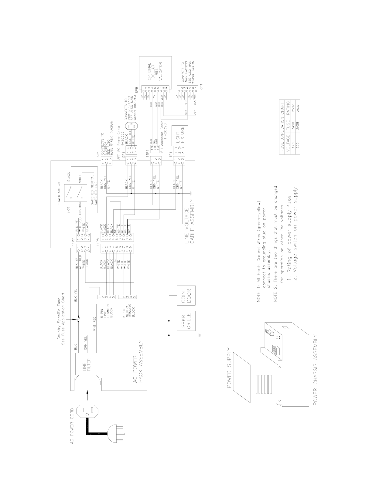
POWER WIRING DIAGRAM
Wiring 5-4
Page 93
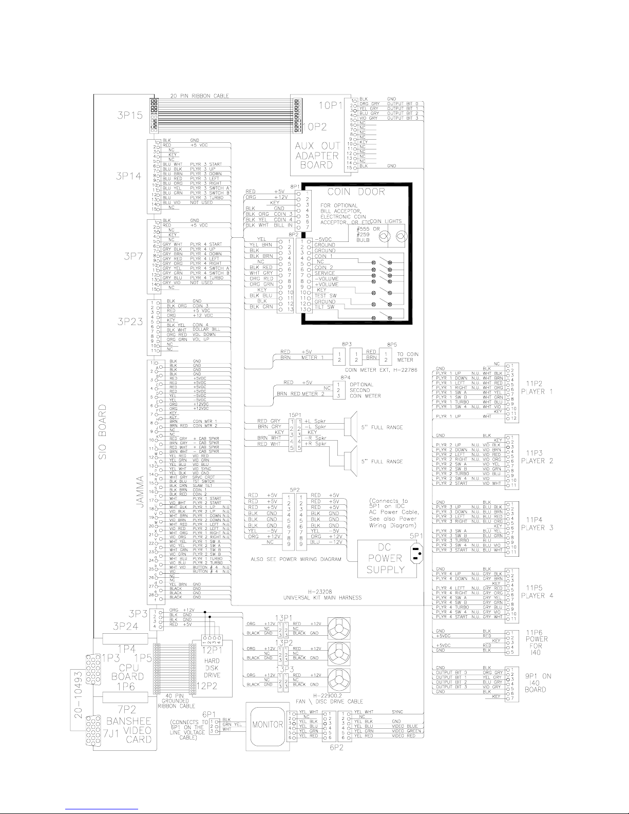
CABINET WIRING DIAGRAM
Wiring 5-5
Page 94
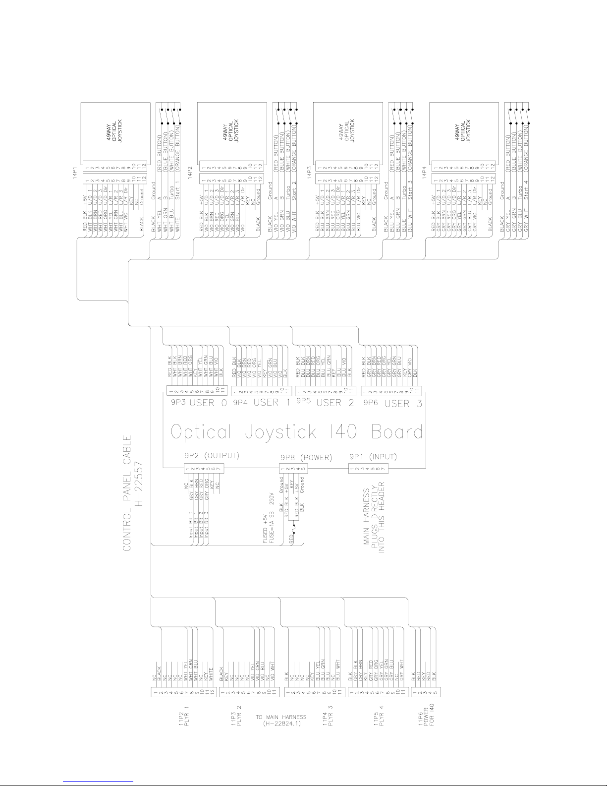
CONTROL PANEL WIRING DIAGRAM
Wiring 5-6
Page 95
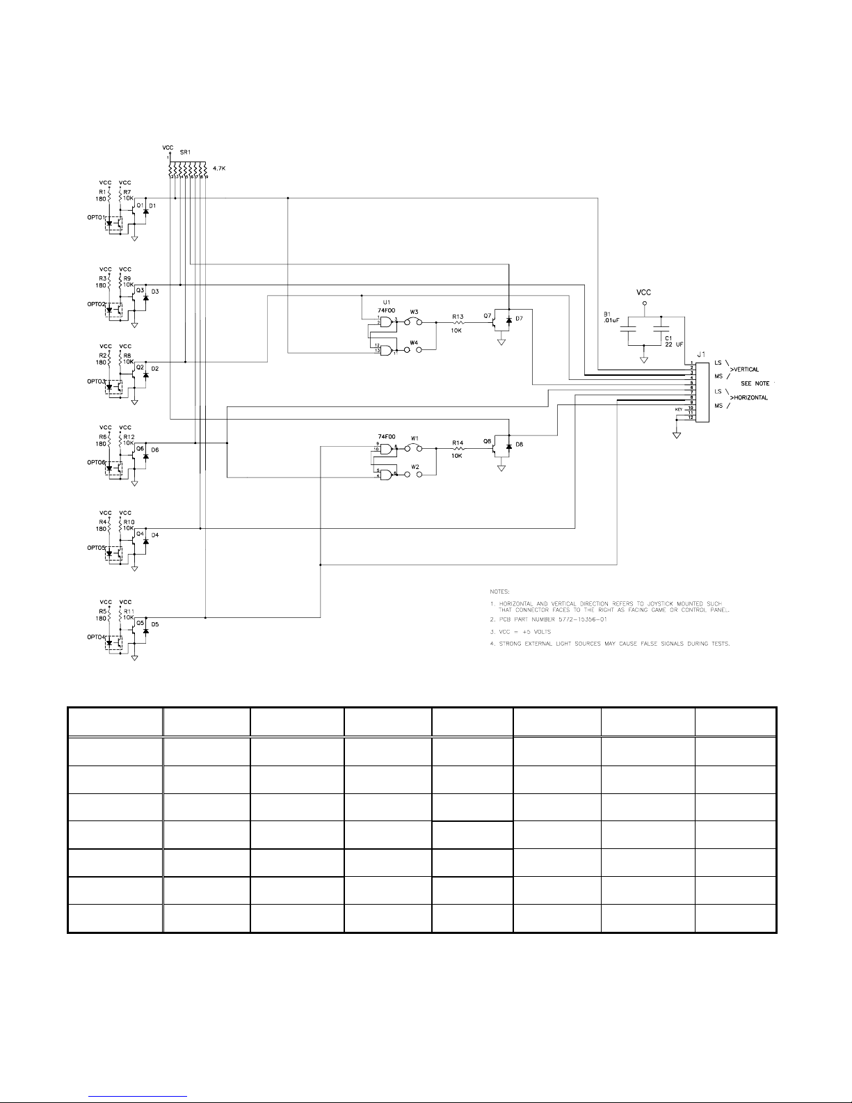
CONTROL WIRING DIAGRAM
(49-WAY JOYSTICK)
POSITION LOGIC TABLE
DIRECTION FULLY
FULLY
UP
MODERATELY
UP
SLIGHTLY
UP
DEAD
CENTER
SLIGHTLY
DOWN
MODERATELY
DOWN
FULLY
DOWN
LEFT
01110111
(00)
00110111
(07)
00010111
(14)
00000111
(21)
11000111
(28)
11100111
(35)
11110111
(42)
NOTE: 1. Connector pin sequence for the above data is as follows: 9 8 7 6 5 4 3 2 referred to ground at pin 12.
2. Numbers in parentheses are found in the Switch Test. Program does not use the “slightly” positions.
MODERATELY
LEFT
01110011
(01)
00110011
(08)
00010011
(15)
00000011
(22)
11000011
(29)
11100011
(36)
11110011
(43)
SLIGHTLY
LEFT
01110001
(02)
00110001
(09)
00010001
(24)
00000001
(24)
11000001
(24)
11100001
(37)
11110001
(44)
Wiring 5-7
DEAD
CENTER
01110000
(03)
00110000
(10)
00010000
(24)
00000000
(24)
11000000
(24)
11100000
(38)
11110000
(45)
SLIGHTLY
RIGHT
01111100
(04)
00111100
(11)
00011100
(24)
00001100
(24)
11001100
(24)
11101100
(39)
11111100
(46)
MODERATELY
RIGHT
01111110
(05)
00111110
(12)
00011110
(19)
00001110
(26)
11001110
(33)
11101110
(40)
11111110
(47)
FULLY
RIGHT
01111111
(06)
00111111
(13)
00011111
(20)
00001111
(27)
11001111
(34)
11101111
(41)
11111111
(48)
Page 96
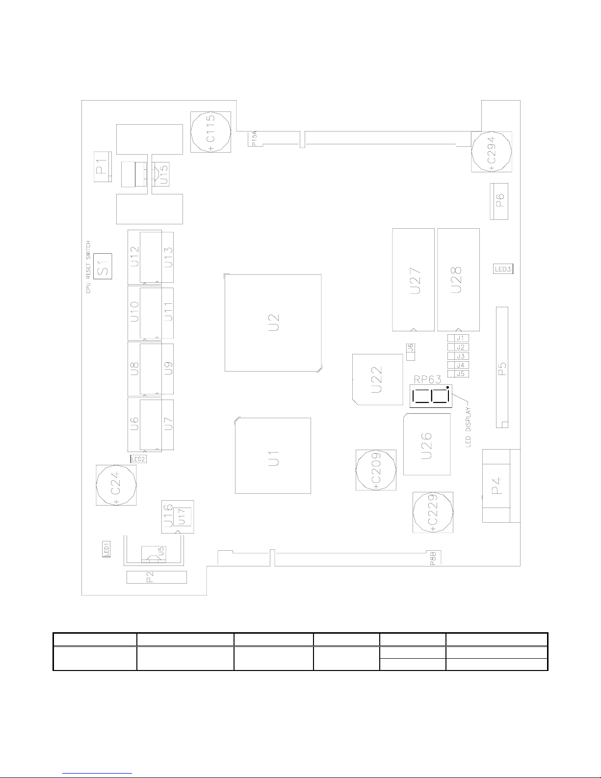
CPU BOARD INDICATOR AND SWITCH LOCATIONS
Switch Location Function Positions State Meaning
U12
*Notes
This switch resets the CPU Board without shutting off power at the power supply.
CPU BOARD SWITCH
Resets and
Restarts Game
Wiring 5-8
2 Off Normal OperationS1* Edge Near U10 and
On Forced Reset
Page 97
CPU BOARD JUMPER LOCATION TABLE
Jumper J1 J2 J3 J4 J5 J6
Located
Near…
U28 &
Connector P5
U22 & U27
CPU BOARD JUMPER POSITION TABLE
ROM Type Default Options* J1 J2 J3 J4 J5 J6
Boot
(U27)
■
Expansion
(U28)
■
27C080, 1M X 8, EPROM 1-2 2-3 1-2 1-2 -- -27C040, 512K x 8, EPROM 1-2 1-2 1-2 1-2 -- -27C010, 128K x 8, EPROM 1-2 1-2 1-2 2-3 -- -29F040, 512K x 8, Flash 2-3 1-2 2-3 1-2 -- -29F020, 256K x 8, Flash 1-2 1-2 2-3 1-2 -- -29F010, 128K x 8, Flash 1-2 1-2 2-3 1-2 -- --
27C080, 1M x 8, EPROM -- -- -- -- 2-3 -27C040, 512K x 8, EPROM -- -- -- -- 1-2 -27C010, 128K x 8, EPROM -- -- -- -- 1-2 --
External
Boot
*
Notes
1. -- = Not Applicable
2. Memory type numbers shown are for blank parts. Your game requires programmed parts.
■
Boot from CPU ROM ----------1-2
Boot from SIO ROM ----------Re-
moved
Wiring 5-9
Page 98
Notes
CPU BOARD LED INDICATOR STATUS TABLE
Device Location Function Color State Meaning
Off Insufficient Power
LED1 Near U6, U7 &
U16
LED2 Near U28 &
Connector P5
RP63 Near U22 &
U26
1. LED1 monitors CPU power (+3.3 volts). If his LED is off or blinking, investigate processor circuits. If other
LEDs are off or blinking at the same time, check +5-volt circuits or the game power supply.
3.3V CPU
Power
Indicator
Hard Disk
Drive
Activity
Indicator Red
Red
Green
On Power OK
Blinking Power Supply Fault
Off Disk Not in Use
On Locked Up Disk
Blinking Normal Disk Activity
Off*
See Note 3, Below.
On*
Blinking*
Sequentially
2. LED2 flashes when the hard disk is operating during game play. LED2 may light continuously during startup. If
this LED remains lighted, the hard drive may be locked up or faulty.
3. Software controls RP63. In this game, RP63 initially indicates program startup stages. This LED is a sevensegment, alphanumeric display device. Normally, RP63 displays a lowercase “b,” or an “O” pattern with
sequentially blinking segments. During Self-Test screens, RP63 displays a “bouncing bar” that resembles a
hyphen (“-“).
Wiring 5-10
Page 99
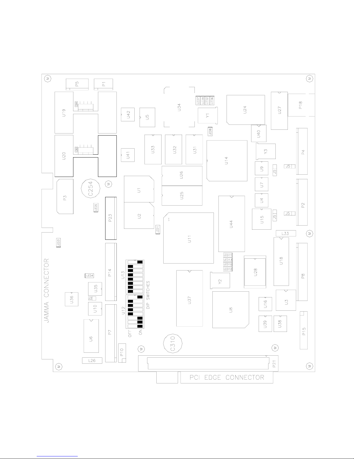
SOUND I/O BOARD ASSEMBLY
Wiring 5-11
Page 100
SOUND I/O BOARD JUMPER POSITION TABLE *
Jumper Location Function Meaning Position State
J1
(Note 1)
Near U9 & Crystal Y3 I/O Connector P2
Input Mode Pins 1 & 2
Output Mode Pins 2 & 3
■
J2 Between U35 & U10 Video Sync
J3
(Note 2)
J4 None None Not Used None
J5
(Note 2)
J6 None None Not Used None
J7 None None Not Used None
J8
(Note 1)
Notes
1. Configure I/O port P2 by setting both jumpers J1 and J8 to input or output mode.
2. Configure I/O port P4 by setting both jumpers J3 and J5 to input or output mode.
Near U15 I/O Connector P4
Between U15 &
Connector P2
Between U9 &
Connector P4
I/O Connector P4
I/O Connector P2
Positive Sync Jumper Not
Negative Sync Pins 1 & 2
Input Mode Pins 1 & 2
Output Mode Pins 2 & 3
Input Mode Pins 1 & 2
Output Mode Pins 2 & 3
Input Mode Pins 1 & 2
Output Mode Pins 2 & 3
■
Installed
■
---
■
---
---
■
Wiring 5-12
 Loading...